Abstract
Use of the subsurface for energy resources (enhanced geothermal systems, conventional and unconventional hydrocarbons), or for storage of waste (CO2, radioactive), requires the prediction of how fluids and the fractured porous rock mass interact. The GREAT cell (Geo-Reservoir Experimental Analogue Technology) is designed to recreate subsurface conditions in the laboratory to a depth of 3.5 km on 200 mm diameter rock samples containing fracture networks, thereby enabling these predictions to be validated. The cell represents an important new development in experimental technology, uniquely creating a truly polyaxial rotatable stress field, facilitating fluid flow through samples, and employing state of the art fibre optic strain sensing, capable of thousands of detailed measurements per hour. The cell’s mechanical and hydraulic operation is demonstrated by applying multiple continuous orientations of principal stress to a homogeneous benchmark sample, and to a fractured sample with a dipole borehole fluid fracture flow experiment, with backpressure. Sample strain for multiple stress orientations is compared to numerical simulations validating the operation of the cell. Fracture permeability as a function of the direction and magnitude of the stress field is presented. Such experiments were not possible to date using current state of the art geotechnical equipment.
Introduction
Multi-physics process-based understanding of the subsurface (0–4 km depth) is increasingly enabling society to address many significant challenges through existing and newly developing technology. Examples include low and high temperature geothermal energy extraction techniques1,2, recovery of conventional and unconventional hydrocarbons3, the storage isolation of substances such as CO2 and toxic radioactive waste4–11, energy storage12,13 and the subsurface injection of liquid wastes14,15. Sustainable management of the subsurface requires the ability to understand, predict and monitor the physical response of the geo-reservoirs and the surrounding rock mass to changes in fluid pressure, stress, temperature, fluid composition and biological activity. These physical responses are often described as combinations of thermal (T), mechanical (M), hydraulic (H), chemical (C), and micro-biological processes (B). All of these processes are interdependent to some degree, with feedbacks and degrees of coupling among themselves that depend on the particular situation and technology under consideration.
Experimental approaches provide an opportunity to gain better understanding of process interactions and provide quantitative values that underpin the development and calibration of behavioural laws. A primary motivation for the experimental apparatus development reported here is to progress the capability for experimental investigation of coupled THM processes in geo-reservoirs under in-situ condition controls that are beyond the current state of the art. The design goals for this development emphasise large samples to allow more complexity of the fracture(s) within the sample, the capability of achieving rotatable, true-triaxial stress states, the ability to heat the sample in the apparatus and the ability to investigate fluid flow through the sample under controlled conditions. To date this has not been possible within a single experiment. This paper describes the new apparatus and initial operational outcomes that demonstrate its capabilities.
Previous Work and Context
Understanding the behavior of rocks under representative stress states has long been a goal of rock mechanics research. The first so-called triaxial testing equipment, the “von Kármán cell”16 enabled the investigation of brittle and ductile rock failure. In the von Kármán cell, a uniform axi-symmetric radial loading is exerted by means of a pressurized fluid in the annulus between the walls of the pressure cell and the sample. The design served as a blue print for many variations to follow, with the “Hoek-Franklin cell”17 becoming widely adopted in the field of rock mechanics, along with similar cell designs18,19. The International Society of Rock Mechanics (IRSM) describe the use of such cells as a standard for rock failure testing20.
However these conventional triaxial cells, are strictly only able to create conditions that are representative of two specific triaxial stress states21–26.
| 1 |
| 2 |
Actual measurements indicate that the three principal stresses are rarely equal in the natural setting27,28. Analytical and numerical calculations show that the general condition is one of “true triaxial” conditions, in which the principal stresses are unequal:
| 3 |
The intermediate principal stress has an important influence on the criterion that defines rock failure and both normal and shear stress across fracture plains, which in turn significantly influences the fluid flow properties of the rock mass19,29,30. This emphasises the need to represent true triaxial 3D stress conditions, and led to the development of true triaxial testing (TTT) equipment31,32 (and references therein). In a review of the history of TTT apparatuses21, three main categories of testing equipment are identified, (i) rigid platen type, (ii) flexible medium type, and finally (iii) mixed type. Almost all TTT testing relies on cubic samples, and most have a sample size with an edge length of under 10 cm. All cubic samples are limited to one orientation of the principal stress axes with respect to discontinuities and/or strength anisotropy, though the actual magnitude of the stresses may be varied e.g.33–38.
A number of new TTT cells have been developed for specific purposes, for example the visual observation of deformation of prismatic samples through a sapphire window39, hydraulic fracturing of differently sized cubic specimens40,41, and rapid unloading to simulate rock burst conditions42–46. A TTT cell has been developed capable of containing larger samples for testing enhanced geothermal systems (EGS) with a side wall dimension of 300 mm and enabling the whole cycle of an EGS development, from drilling multiple boreholes during heating and mechanical loading through to production and post-production47. Larger samples (500 mm × 500 mm × 500 mm) to capture representative elementary volume (REV) scale results have also been investigated48. However, samples larger than 300 mm side length require specialist preparation and handling equipment due to their weight, and multiple sample testing in the laboratory is challenging.
Fluid flow in the subsurface occurs both in the matrix pore system and fractures. Understanding flow under different stress conditions is important: current TTT apparatus facilitates measurements of effective permeability, pore pressures up to 35 MPa, elevated temperatures (of up to 200 °C), as well as imaging of the sample through both P and S wave velocities, acoustic emission monitoring, and electrical resistivity36. Other designs allow further fluid sealing49 and increased loading capacity50. Commercial true tri-axial testing apparatus products, such as TerraTek hydraulic fracturing cells, DCI Test Systems’ polyaxial stress frame, or Wille-Geotechnik’s advanced true triaxial test system, are also available and commonly used to investigate rock strength and hydraulic fracturing51,52.
To the knowledge of the authors, there is only one example of a cell capable of applying a rotatable stress field to cylindrical samples with a diameter of 38 mm and length of 76 mm, the SMART cell24,53,54. The use of cylindrical specimens has a significant advantage over the cubic samples since it reduces the concentration of stresses at the sample edges overcoming the problem of the blank loading corners21,33. However, the issue of end effects due platen friction leading to a stress shadow where the vertical loading plates contact the top and bottom surfaces of the sample is still important, and taken into account in the evaluation of the stress field developed in the sample through modelling and strain measurement.
The GREAT cell (Geo-Reservoir Experimental Analogue Technology) presented here represents a mixed type “polyaxial cell” capable of creating principal stresses from multiple directions, and even irregular distributions of stress without the need to re-position the sample. The GREAT cell represents a significant advancement in testing capability with respect to sample size, stress control and monitoring technology. The technological development embodied in the cell progresses the radial pressure concept illustrated by the SMART cell, with a new radial hydraulic pressure system that can accommodate more sample displacement and higher loading than was possible in the SMART cell. It involves a complete redesign of the radial loading concept and mechanics, ensuring minimal interference between pressure exerting elements. The GREAT cell is designed to recreate in situ conditions found at depths of 3 to 4 km in geo-energy applications in terms of triaxial polyaxial stresses to 100 MPa, temperatures up to 100 °C and fluid pressure up to 40 MPa with flow. The sample size of 0.2 m diameter facilitates the investigation of fracture networks, with specially-positioned fluid ports selecting specific fluid flow channels/features within the samples. Rotation of the stress field during experiments enables investigation of the behavior of fractures and fracture networks under changing loading conditions. The strain response and, in future experiments, the temperature response, of the samples are monitored through the use of state of the art fibre optic cable providing thousands of detailed all around measurements. Multiple pressure sensors provide detailed real time stress and fluid pressure measurements of the loading applied.
We demonstrate the operational capability of the cell for two different synthetic samples, a homogeneous sample and a sample hydraulically fractured between two artificial boreholes. The first set of experiments is the simplest possible, with a homogenous material demonstrating mechanical deformation. The second is relevant to hydraulic fracturing for enhanced geothermal systems, where a doublet of wells is being engineered, but also to fracturing for shale gas where such a short-cut is undesirable, and where each subsequent hydraulic stimulation will change the stress orientation on the fractures in the preceding fracture stage.
In the second sample, flow is induced between the boreholes in a stress field that is rotated, allowing the flow changes as a function of stress to be determined. To our knowledge, this has not been achieved before. The aim of investigating artificial samples is to demonstrate that the GREAT cell could (a) exert a controllable, rotatable poly-axial stress field, (b) facilitate detailed surface strain monitoring of the surface deformation of the sample and (c) contain fluid flow with considerable backpressure through samples in a rotating stress field.
The homogeneity of the undeformed artificial sample allows the deformation of the sample and subsequent strain response to be benchmarked against standard mathematical models for elastic behaviour. Experimental testing is undertaken over a period of a few hours with repeated loading and unloading performed in different orientations thereby reducing the possibility of longer term visco-plastic deformation of the synthetic material used (polyester). In the future, the repeatability of measurements will also enable the plastic and elastic responses of the rock under cyclical loading and different stress states to be investigated. Understanding the mechanical impact of more frequent cyclic loading/unloading operations is particularly important for energy storage in subsurface systems. Strain on the surface of the sample is determined using optical fibre technology, providing high-resolution spatial data, and providing a possible strain value (axial or circumferential) at a spacing of 2.5 mm along the length of the fibre. The low elastic modulus of the sample material (~4 GPa, compared to natural rocks that are typically 20 GPa+) constrains the stress magnitudes that can be achieved with the artificial material because radial deformation of more than 2–3 mm on a sample with a radius of 100 mm would compromise the integrity of the optical fibre. The current testing was undertaken with a rotating triaxial stress field (σx > σy) from 2 MPa to 10 MPa, (equivalent to the rock stress expected at 100 to 500 m depth) and with fluid in the fracture at pressures up to ~4 MPa (~400 m depth). This amount of deformation can be considered equivalent to a test of ~40 MPa true triaxial stress on a rock sample, which can be mapped to rock stress exerted at a depth of ~1.5 km. Numerical modelling of the deformation and comparison to the circumferential strain measurements indicate that the cell is able to create a rotatable true triaxial stress field and that deformation of the sample surface can be accurately recorded.
A significant difference in circumferential-surface deformation of the unfractured and hydraulically fractured samples is observed, even where the fracture has not propagated to the surface of the sample. Rotating the stress field allowed investigation of the impact of the fracture orientation on the surface deformation, relative to the external principal stress directions. Within a numerical model of this experiment, a generic fracture of similar geometry to that within the sample gives results that match the observed deformation, illustrating that deformation processes occurring deep in the sample can be detected remotely at the sample surface using the fibre optic monitoring equipment.
Fluid flow was induced through the fracture under different stress orientations by flowing through two boreholes connected to the fracture. Permeability of the fracture is found to be a function of the normal stress across the fracture plane55 (and references therein), a result further confirming the operation of the cell.
The GREAT cell was then used to raise the temperature of the sample by some 20–30 °C in an unconfined state, and allowed to cool down again after which the fluid flow experiment was repeated with a fracture fluid pressure of 3.2 MPa, simulating raised pore pressures. Heating led to some plastic deformation of the fracture and a reduction in permeability.
Design of the GREAT cell
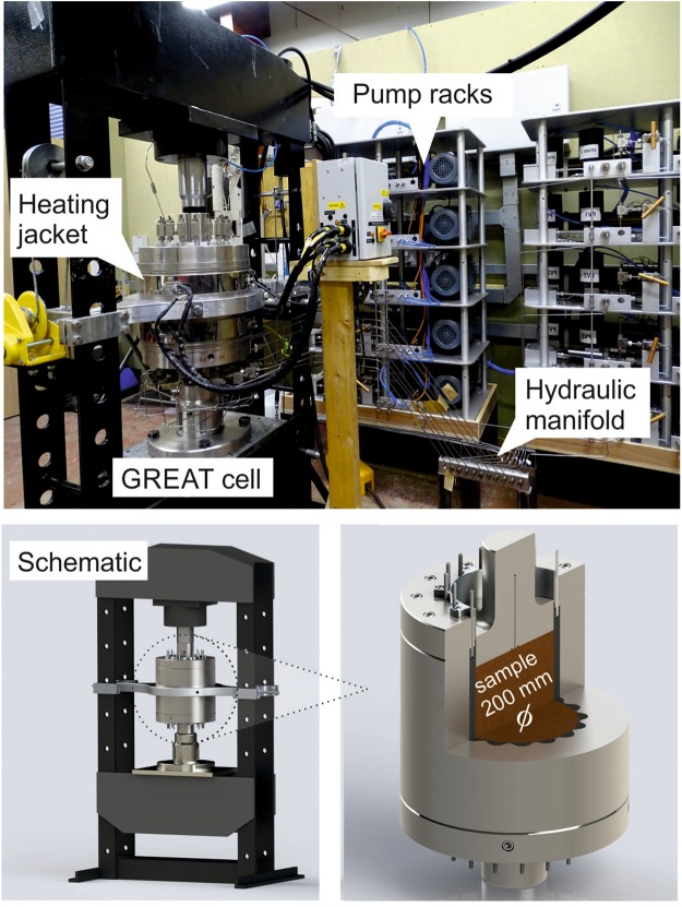
The GREAT cell (Fig. 1) is designed to accommodate large, bench-scale cylindrical samples (approximately 200 mm diameter × 200 mm length) and to subject them to conditions of temperature, pressure, and fluid pressure representative of subsurface conditions, including true triaxial stress conditions. As such, the design criteria require a full working range of 100 MPa radial and axial loading, temperatures of up to 100 °C, and pore pressures up to 40 MPa. In addition, the poly-axial design criterion necessitated the individual control of the radial loading mechanism.
Figure 1.
GREAT cell experimental apparatus.
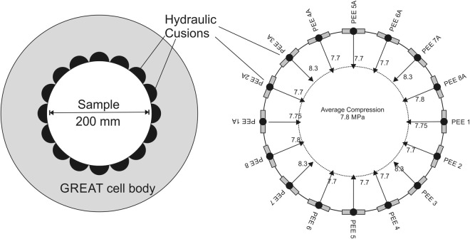
The radial pressures are applied to the sample by eight opposing pairs of fluid filled flouro-elastomer (Viton) tubes, forming hydraulic cushions, termed Pressure Exerting Elements (PEEs). The PEEs have a large-radius face that matches the sample diameter, and a short-radius back that fits into recesses in the cell body (Fig. 2). The PEE pairs are connected to automatically controlled pressure generator pumps. Each PEE pair is connected hydraulically and pressurised by the same pump ensuring the same pressure is exerted symmetrically on opposite sides of the sample.
Figure 2.
Concept of hydraulic cushions exerting a radially controlled stress field on a sample with a diameter of 200 mm, PEE labelling refer only to experimental notation, numbers with arrows refer to fluid pressure in PEE during a particular experiment given as an illustration.
Individual PEEs are prevented from influencing the pressure in the neighboring PEEs by a Dynamic Sealing Strip (DSS). Currently a 2mm-thick Viton sheath is placed between the sample and the PEEs/DSSs to protect the fibre optic cable attached to the sample and to ensure a complete hydraulic seal around the sample during fluid flow experiments.
Fluid flow through a sample is achieved with a separate hydraulic system controlled by LabVIEW and supported by separate pumps. Fluid enters and leaves the cell through the top platen via two fluid ports to allow fracture flow-through tests – one central port and a second at a radius of 50 mm. The platen design allows the use of a distribution plate to ensure fluid access to parts or the whole of the sample’s end surface. It is also possible to record the temperature of the fluid entering and leaving the sample through two in-line thermocouples on the inlet and outlet flow lines.
Sample temperature is controlled using electro-resistance heating bands located circumferentially around the main cell body, spaced evenly in the axial direction. An insulating jacket encompasses the whole cell including the plumbing and the hydraulic loading ram. Thermal breaks are used between the cell body support and the loading frame.
Strain data on the sample deformation is recorded using a fibre optic strain gage along with the ODiSI-B software produced by LUNA Inc. This fibre enables an extremely high resolution of fibre-parallel strain to be determined around the cylindrical surface of the sample: e.g., a 1 m length cable corresponds to an equivalent of 461 possible strain gage points. A groove <1 mm deep was cut into the sample surface into which the optical fibre for measuring strain was attached.
Experimental Program
We present the results of three different experimental programs, listed in Table 1. All further data is available from the corresponding author on request.
Table 1.
Unique aspects of experimental tests.
| Test name | Unique aspect of test | Description of sample |
|---|---|---|
| Mechanical Test (M1) | Mechanics only Rotating triaxial stress field | Homogeneous artificial sample Opaque amorphous thermoplastic polymer |
| Hydromechanical Test (HM1) | Hydraulics and Mechanics Fluid flow through fracture in rotating triaxial stress field stress field | Artificial hydraulically fractured sample Transparent polyester resin |
| Hydromechancial Test (HM2) | As HM1, with significant fracture fluid pressure (4 MPa) | As HM1 after being further thermally fractured in cell Transparent polyester resin |
The sample for the mechanical tests M1 is made from an opaque amorphous thermoplastic polymer, whilst the sample for the fracture flow tests (HM1 & HM2) was made from a transparent polyester resin. A uniaxial compression hydraulic fracturing rig was used to generate a hydraulic fracture within sample HM1 through a central borehole. A second borehole was then drilled into the sample to create a dipole fluid flow scenario within a confined fracture of dimensions 95 mm high × 65 mm width (Fig. 3). Once the HM1 tests were complete, the sample was heated in the GREAT cell, and afterwards found to have thermally fractured and thus the fracture extended to the cylindrical margin of the sample. This sample then formed the basis for the test sequence HM2.
Figure 3.
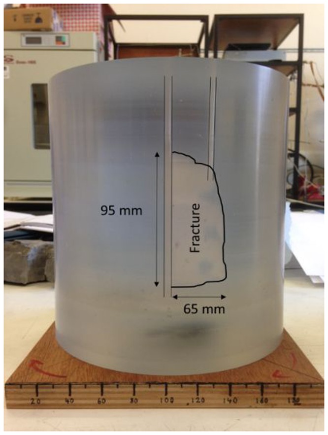
The prepared sample showing the location of the fracture (edge is highlighted on the photo) and boreholes in HM1 & HM2 experiments.
The samples were loaded first with a vertical stress of 8.2 MPa in the M1 test and 10 MPa in the HM tests, representing σ1. Then for all tests, initially an equal radial compression is applied through the PEEs, and then the PEEs are adjusted to create a triaxial stress field with σ1 > σ2 > σ3, of the order of 8 MPa for σ2 to 2 MPa for σ3. A detailed listing of the PEE pressures for the experiments presented here in each test stage for M1, HM1 and HM2 is given the Supplementary Information. The fracture flow tests of HM1 and HM2 were conducted under different flow conditions, HM1 had a flow rate of 30 ml/min with the downstream pressure being ambient atmospheric conditions, HM2 was conducted at a flow rate of 25 ml/min with a fluid downstream back pressure of 3.45 MPa. In each case, flow rate and fluid pressure were recorded at a frequency of 1 Hz, and sample-surface strain was recorded at 25 Hz.
Benchmarking the Experimental Results by Numerical Modelling
To assess whether the GREAT cell is creating the internal stress field expected, the operation of the cell is simulated using the open source coupled THMC processes simulator OpenGeoSys (www.opengeosys.org). Modelling a deforming 3D body with multiple traction terms, boundary conditions, multiple layers and time dependent application of stress is a non-trivial exercise. The theory and several benchmarks regarding the use of OGS may be found in56, and general FE theory found in30. Here, the numerical calculation of the elastic deformation and surface strain is compared to the measured deformation of the samples during the experiments.
A cylindrical structured mesh representing the sample was created using Gmsh software57. The mesh geometry and density were designed to ensure that nodes correspond to key sample geometrical features. For multi-stage experiments involving axial loading, followed by true triaxial radial loading and then rotation of those loads, stage-dependent traction loads are applied. We define zero circumferential-displacement boundary conditions along the vertical lines that define the sample circumference intersection with the x- and y-axes, and a zero displacement in the z-direction across the entirety of the sample base (Fig. 4). This simulates the sample assuming no end effects though end plate friction. To include the possibility of endplate friction, the worst possible case is simulated by defining zero displacement in the x- and y- directions across the entirety of the sample top and base.
Figure 4.
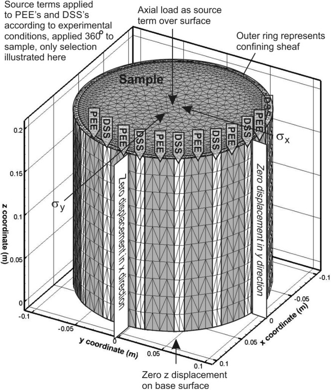
Conceptual numerical model, illustrating mesh, selection of boundary conditions and application of source terms to represent experimental conditions.
To simulate the experiments HM1 and HM2 it was necessary to represent the fracture in the numerical mesh. Elements belonging to the fracture volume have a sub-millimetre thickness and are assigned an elastic modulus significantly less (>10 x reduction) than the surrounding intact material, thereby representing a softened region in the elastic continuum.
Three models are presented here. Each model simulates both the axi-symmetric stress field σ1 > σ2 = σ3 and the true triaxial stress field σ1 > σ2 > σ3. The models were realised by varying stage-dependent traction terms, boundary conditions, material properties or meshes as reflecting the experimental conditions. Model 1 simulates the experimental test M1, Model 2 simulates tests HM1&2, but without taking into account the presence of the fracture, and Model 3 simulates HM1 & HM2 with a discrete fracture included in the numerical mesh. The elastic material properties used to simulate all tests are given in Table 2. The actual samples used for M1 and HM1&2 were made from different materials, thus the elastic parameters are different, although all are representative of literature values for these materials.
Table 2.
Parameters of elastic models used to simulate GREAT cell results.
| Sample | Model 1 | Model 2 | Model 3 |
|---|---|---|---|
| (M1) | (HM1&2) | (HM1&2) | |
| Parameter | |||
| Sample Youngs Modulus (GPa) | 3.85 | 4.3 | 4.3 |
| Sample Poisson Ratio | 0.4 | 0.4 | 0.4 |
| Fracture Youngs Modulus (GPa) | 0.3 | ||
| Fracture Poisson Ratio | 0.4 | ||
| Containing Sheaf Young Modulus (GPa) | 0.1 | 0.1 | 0.1 |
| Containing Sheaf Poisson Ratio | 0.4 | 0.4 | 0.4 |
Results
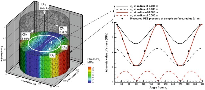
The results of the simulation (for the loading case: σ1 = σaxial = 10 MPa, σ2 = 8 MPa, and σ3 = 2 MPa) for an ideal sample with no top surface or bottom surface boundary friction effects (“friction free sample”) are illustrated in Fig. 5. The simulation shows that the loading scheme creates an almost-correct and almost-homogeneous true-triaxial state in the sample volume. The small discrepancies between the ideal target state and the one that can be achieved are associated with the inability to apply shear tractions on the curved exterior surface. In the experiment, the sample circumference is everywhere a principal plane (as it is in all similar experimental designs), whereas a true-triaxial state would resolve onto planes with those orientations as a combination of normal and shear tractions. For the worst case end effect due to friction on the endplate a small reduction in the intensity of the stress field at the radius of 0.065 m is calculated of the order of <0.5%. The maximum difference noted in the center of the sample was of the order of 15% for the minimum principal stress, and 4% for the maximum principal stress. Although the average surface strains for the two models are within 4%, the period of the strains are shifted by 90 degrees, providing a useful way to determine the relative influence of any end effects. It is clear from these results that controlling the pressure in the PEEs facilitates a controlled triaxial stress field with user defined orientation within the sample.
Figure 5.
Numerical simulation of the stress field in M1 test, σ1 > σ2 > σ3, graph gives stress at locus of points shown by white circle at radius 0.065 m, PEE pressures measured at sample surface.
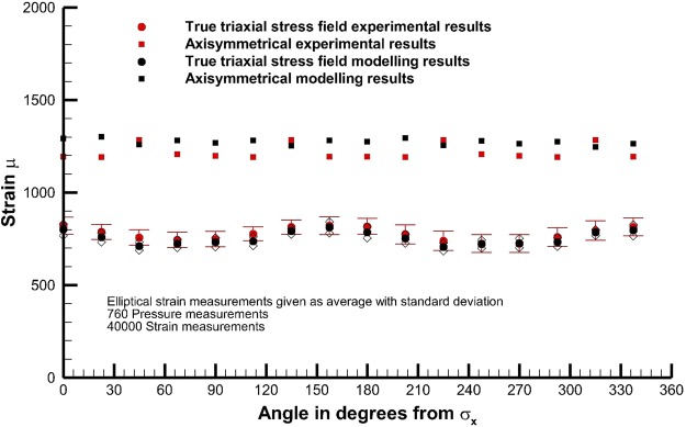
The measured and modelled surface strains for experiment M1 show a good consistency (Fig. 6). Here, 80 pressure measurements and 4000 strain measurements for the axi-symmetric radial loading case (σ1 > σ2 = σ3) are presented, as well as 760 pressure measurements of PEE pressure and 40000 measurements of strain for the true triaxial loading case (σ1 > σ2 > σ3). The model used superimposes with equal weighting a friction free sample and the worst end effect possible. The results demonstrate that the actual experiment performs very closely to the design. The true triaxial stress field measurements are shown as superimposed results derived from multiple physical orientations of the stress field on the actual sample. That is, a certain number of measurements were made with the stress field located in a certain orientation, the stress field was then rotated, and the strain then re-measured, repeated for 8 different orientations of the stress field. The results are presented relative to the orientation of the experimental principal stress axes.
Figure 6.
Comparison between experimentally measured strain and model simulations for Test M1, bars give standard deviation.
Strain measurement locations on the sample were selected at 16 locations at the centre of the PEEs, halfway up the sample, with a radial interval of 22.5°. The mesh density of the numerical model enabled extraction of strain every 2.5°, i.e. with a much higher resolution than experimentally recorded, in addition linear interpolation between adjacent points gives a value of strain exactly corresponding to the location of the measurement. The surface strain is determined by the local change in length in the fibre optic cable. This is associated with a combination of the circumferential and radial strain components inside the sample itself.
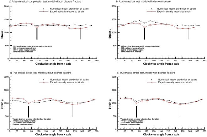
Figure 7a illustrates the results of experiment HM1 assuming friction free conditions without explicitly including a fracture (Model 2), and leads to a moderate match of the surface deformation profile (within 250 µ) for the simpler axisymmetric (σ1 > σ2 = σ3) loading. This can be compared with the good match (within 100 µ and profile) depicted in the upper part of Fig. 6 for M1, for which both experiment M1 and Model 1 do not contain a fracture. Immediately obvious in Fig. 7a is that the location of the fracture (thick black line) in the sample is having a significant influence on the surface strain distribution. When a fracture is included in the numerical mesh (Model 3), illustrated in Fig. 7b, the match is significantly improved, clearly indicating that the fracture is the dominant factor determining the change in the surface strain when compared to the case where there is no fracture.
Figure 7.
Comparison of the experimentally measured surface strains of a sample with a discrete fracture in it with model predictions with and without the inclusion of a discrete fracture in the mesh, for the axisymmetric radial compression test and a true triaxial stress field test.
For the true triaxial loading case, Fig. 7c illustrates the comparison of the measured surface strain with the prediction of the numerical model without a discrete fracture in the mesh and Fig. 7d depicts the prediction with a discrete fracture in the mesh. The comparison of these results suffices to illustrate the GREAT cell is capable of detecting the surface strain expression of the fracture in a sample, and that numerical modelling is a viable means of constraining some important sensitivities to the fracture properties and orientation, which can be fitted to the observations obtained from the GREAT cell.
In both test sequences HM1 and HM2, the relationship between the orientation of the principal stress axes and the flow properties of the fracture could be investigated. The normal stress across the fracture was calculated from the orientation and magnitude of the principal stresses assumed if true-triaxial conditions are achieved inside the sample, using the orientation of the fracture plane relative to these axes (Equation 4).
| 4 |
where the orientation of the fracture to the principal stress axes is described by the directional cosines l, m, n.
The fluid pressure and flow rate through the fracture was recorded as a function of loading. The results for the fluid flow measurement in HM1 and HM2 are presented in the Supplementary Information. For the HM1 tests no downstream fluid pressure was applied, whereas for HM2 a downstream fluid pressure ~3.2 MPa was maintained. The permeability of the fracture was evaluated (Equation 4), and the effective aperture of the fracture determined. The fracture aperture e (m) is calculated using the cubic law approximation58 where Q (m3/s) is the volumetric flow across the sample through the boreholes, (Pa/m) is the pressure gradient between the boreholes, µ (Pa.s) is the dynamic viscosity, w is the fracture width (0.095 m, see Fig. 3) and Δx is the fracture length (0.05 m see Fig. 3).
| 5 |
The intrinsic permeability k (m2) of the fracture is calculated from the fracture aperture e (m) as
| 6 |
Fracture permeability is plotted against the calculated normal stress across the fracture plane, depending on the orientation of the stress field (Fig. 8). The results demonstrate a clear and consistent change in the permeability of the fractures with the change in the orientation of the stress field, and the change in normal stress on the fracture plane due to the rotation of the stress field. These results demonstrate that the GREAT cell can be used to investigate the flow effects of contained fractures inside a large sample. The increased error in the measurement of the HM2 experiments over the HM1 experiments is related to the extra pump control required to maintain a significant downstream pressure.
Figure 8.
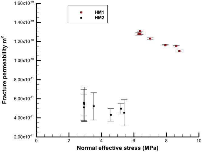
Plot of effective normal stress and change in permeability for fractures in HM1 & HM2 (HM1 376 measurements, HM2 460 measurements, error bars give standard deviation).
Conclusions
The GREAT cell has the operational capacity to recreate representative reservoir conditions of a true poly-axial stress state/field in 200 mm diameter samples. This capability facilitates studies of fluid flow through fractures (and, in the future, investigation of coupled processes in fractured-porous media, fracture-+matrix samples interaction), and will provide opportunities to extend the range of parameters and conditions which are considered important in fracture-dominated flow. Optical fibre cable sensing of surface strain facilitated thousands of detailed strain measurements that provide good constraints for numerical models of the internal processes. There is an excellent correlation between imposed loading conditions, presence and character of the fracture in the sample, and material behavior. Dipole fluid flow through a fracture accessed by two artificial boreholes proves the fluid sealing capability of the cell. During fluid flow the triaxial stress field was rotated causing the normal stress across the fracture to change. There is a clear proportional relationship between the resolved normal stress and the effective flow in the fracture. The GREAT cell provides a step change in technology to experimentally investigate the coupled process behavior of natural reservoir material under in situ conditions of temperature, fluid flow, stress and chemistry. In particular, this technology advances the ability to investigate large diameter samples including fractures under in situ conditions of stress and temperature, to rotate a true triaxial stress field during a flow experiment, to provide fracture and matrix flow measurement with and without downstream pressure, and to provide thousands of detailed real time strain measurements on the surface deformation of the sample.
Electronic supplementary material
Acknowledgements
The research leading to the development of the GREAT cell and the results presented have been supported by a University of Edinburgh College of Science and Engineering capital equipment grant, internal investment by Heriot Watt University, by the German Science Foundation (Deutsche Forschungsgemeinschaft, DFG, grant: INST 186/1197 - 1 FUGG), and the German Lower Saxony Ministry of Science and Culture (Niedersächsisches Ministerium für Wissenschaft und Kultur, MWK, grant 11 – 76251-10-5/15 (ZN3271)), and by funding from the European Union’s Horizon 2020 research and innovation programme under grant agreement No 636811. The development of the OpenGeoSys platform for geotechnical applications is also supported by the Federal Ministry of Education and Research (BMBF) under grant 03G0866A (GeomInt). The authors would also like to thank the anonymous reviewers.
Author Contributions
C.I. McDermott, lead author and principal investigator//overall manager of project GREAT cell. Responsible for formation of original idea, and main ideas of experimental equipment design, responsible for modelling work, obtained grants with a value of £600k to support project. A. Fraser-Harris, responsible for experimental work in paper and final development//technical implementations of GREAT cell to make it all work. M. Sauter, responsible for formation of original idea, ongoing development of project and obtaining grants to support the project with a value of £300k, management of University of Goettingens input into project. G. Couples, responsible for formation of original idea, ongoing development in project, contribution of IP to regular design, build and management meetings, fundraising for the project £200k, and management of Heriot Watt University’s input in the project. K. Edlmann, provided SMART cell expertise, contributed IP to design, build and management meetings of project, and assisted in the experimental work both during initial design and commissioning. O. Kolditz, preparation, writing and general provision of the finite element code OpenGeoSys, applied to model the GREAT cell results. A. Lightbody technical support and assistance in experimental operations, design and build and finding ongoing solutions to technical issues faced in operating the GREAT cell. J. Somerville, provided SMART cell expertise, contributed IP to design, build and management meetings of project. W. Wang, implementation and support of the deformation routines within the framework of OpenGeosys. Support on multiple aspects of using OpenGeoSys.
Data Availability
We present the results of three different experimental programs, listed in Table 1, within the manuscript and Supplementary Information. Original experimental data (0.25 GB), and model simulations (2.8 GB) is available from the corresponding author on request.
Competing Interests
The authors declare no competing interests.
Footnotes
Publisher's note: Springer Nature remains neutral with regard to jurisdictional claims in published maps and institutional affiliations.
Electronic supplementary material
Supplementary information accompanies this paper at 10.1038/s41598-018-32753-z.
References
- 1.Tomac Ingrid, Sauter Martin. A review on challenges in the assessment of geomechanical rock performance for deep geothermal reservoir development. Renewable and Sustainable Energy Reviews. 2018;82:3972–3980. doi: 10.1016/j.rser.2017.10.076. [DOI] [Google Scholar]
- 2.McDermott CI, Randriamanjatosoa ARl, Tenzer H, Kolditz O. Simulation of heat extraction from crystalline rocks: The influence of coupled processes on differential reservoir cooling. Geothermics. 2006;35:321–344. doi: 10.1016/j.geothermics.2006.05.002. [DOI] [Google Scholar]
- 3.Ilgen AG, et al. Shales at all scales: Exploring coupled processes in mudrocks. Earth-Science Reviews. 2017;166:132–152. doi: 10.1016/j.earscirev.2016.12.013. [DOI] [Google Scholar]
- 4.Tsang C-F, Neretnieks I, Tsang Y. Hydrologic issues associated with nuclear waste repositories. Water Resources Research. 2015;51:6923–6972. doi: 10.1002/2015WR017641. [DOI] [Google Scholar]
- 5.Fraser Harris, A. P., McDermott, C. I., Bond, A. E., Thatcher, K. & Norris, S. A nonlinear elastic approach to modelling the hydro-mechanical behaviour of the SEALEX experiments on compacted MX-80 bentonite. Environmental Earth Sciences75, 10.1007/s12665-016-6240-y (2016).
- 6.Fraser Harris AP, McDermott CI, Kolditz O, Haszeldine RS. Modelling groundwater flow changes due to thermal effects of radioactive waste disposal at a hypothetical repository site near Sellafield, UK. Environmental Earth Sciences. 2015;74:1589–1602. doi: 10.1007/s12665-015-4156-6. [DOI] [Google Scholar]
- 7.McDermott C, et al. Screening the Geomechanical Stability (Thermal and Mechanical) of Shared Multi-user CO2 Storage Assets, a Simple Effective Tool Applied to the Captain Sandstone Aquifer. International Journal of Greenhouse Gas Control. 2016;45:43–61. doi: 10.1016/j.ijggc.2015.11.025. [DOI] [Google Scholar]
- 8.Vilarrasa V, Rutqvist J. Thermal effects on geologic carbon storage. Earth-Science Reviews. 2017;165:245–256. doi: 10.1016/j.earscirev.2016.12.011. [DOI] [Google Scholar]
- 9.Tong F, Jing L, Zimmerman RW. An effective thermal conductivity model of geological porous media for coupled thermo-hydro-mechanical systems with multiphase flow. International Journal of Rock Mechanics and Mining Sciences. 2009;46:1358–1369. doi: 10.1016/j.ijrmms.2009.04.010. [DOI] [Google Scholar]
- 10.Bauer S, et al. Modeling, parameterization and evaluation of monitoring methods for CO2 storage in deep saline formations: the CO2-MoPa project. Environ. Earth Sci. 2012;67(2):351–367. doi: 10.1007/s12665-012-1707-y. [DOI] [Google Scholar]
- 11.Birkholzer, J. T. et al. DECOVALEX-2015: an international collaboration for advancing the understanding and modeling of coupled thermo-hydro-mechanical-chemical (THMC) processes in geological systems. Environ. Earth Sci. 77(14), art. 539 (2018)
- 12.Kushnir R, Ullmann A, Dayan A. Compressed Air Flow within Aquifer Reservoirs of CAES Plants. Transport in Porous Media. 2010;81:219–240. doi: 10.1007/s11242-009-9397-y. [DOI] [Google Scholar]
- 13.Kabuth, A. et al. Energy storage in the geological subsurface: dimensioning, risk analysis and spatial planning: the ANGUS+ project, Environ. Earth Sci. 76(1), art. 23 (2017)
- 14.Saripalli KP, Sharma MM, Bryant SL. Modeling injection well performance during deep-well injection of liquid wastes. Journal of Hydrology. 2000;227:41–55. doi: 10.1016/S0022-1694(99)00164-X. [DOI] [Google Scholar]
- 15.Liu, Y., Xu, J. & Peng, S. An Experimental Investigation of the Risks of Triggering Geological Disasters by Injection under ShearStress. Scientific Reports 6 (2016). [DOI] [PMC free article] [PubMed]
- 16.Karman, T. V. Festigkeitsversuche unter allseitigem Druck. Zeitschrift des Vereines Deutcher Ingenieure55 (1911).
- 17.Hoek E, Franklin JA. Simple triaxial cell for field or laboratory testing of rock. Transactions of the Institution of Mining and Metallurgy. 1968;77:A22–26. doi: 10.1016/j.ijrmms.2004.09.015. [DOI] [Google Scholar]
- 18.Heard HC. Effect of large changes in strain rate in the experimental deforamtion of Yule Marble. Journal of Geology. 1963;71:162–195. doi: 10.1086/626892. [DOI] [Google Scholar]
- 19.Handin J, Heard HC, Magouirk JN. Effects of the intermediate principal stress on the failure of limestone, dolomite, and glass at different temperatures and strain rates. Journal of Geophysical Research. 1967;72:611–640. doi: 10.1029/JZ072i002p00611. [DOI] [Google Scholar]
- 20.Natau OP, Mutschler TO. Suggested method for large scale sampling and triaxial testing of jointed rock. International Journal of Rock Mechanics, Mining Sciences and Geochemical Abstracts. 1989;26:427–434. doi: 10.1016/0148-9062(89)90938-8. [DOI] [Google Scholar]
- 21.Li, X. et al. In True Triaxial Testing of Rocks (eds M. Kwasniewski, X. Li, & Manabu Takahashi) 3–18 (Taylor and Francis Group, 2013).
- 22.Mogi K. Effect of the triaxial stress system on the failure of dolomite and limestone. Tectonophysics. 1971;11:111–127. doi: 10.1016/0040-1951(71)90059-X. [DOI] [Google Scholar]
- 23.Mogi K. Effect of the triaxial stress system on fracture and flow of rocks. Physics of the Earth and Planetary Interiors. 1972;5:318–324. doi: 10.1016/0031-9201(72)90102-1. [DOI] [Google Scholar]
- 24.Smart B, Somerville J, Crawford B. A rock test cell with true triaxial capability. Geotechnical and Geological. 1999;17:157–176. doi: 10.1023/A:1008969308711. [DOI] [Google Scholar]
- 25.Paterson, M. S. & Wong, T. Experimental Rock Deformation - The Brittle Field. (Springer, 2005).
- 26.Jaeger, J. C., Cook, N. G. W. & Zimmerman, R. W. Fundamentals of Rock Mechanics. (Blackwell, 2007).
- 27.Zoback, M. D. Reservoir Geomechanics. (Cambridge University Press, 2010).
- 28.Engelder, T. Stress Regimes in the Lithosphere. (Princeton University Press, 2014).
- 29.Murrell SAF. The effect of triaxial stress systems on the strength of rocks at atomsopheric temperatures. Geophysical Journal International. 1965;10:231–281. doi: 10.1111/j.1365-246X.1965.tb03155.x. [DOI] [Google Scholar]
- 30.Lewis, R. W. & Schrefler, B. A. The finite element method in the static and dynamic deformation and consolidation of porous media. (John Wiley, 1998).
- 31.Mogi K. Effect of the triaxial stress system on rock failure. Rock Mechanics in Japan. 1970;1:53–55. [Google Scholar]
- 32.Kwasniewski, M., Li, X. & Takahashi, M. True Triaxial Testing of Rocks. (CRC Press, 2012).
- 33.Feng XT, Zhang X, Kong R, Wang G. A Novel Mogi Type True Triaxial Testing Apparatus and Its Use to Obtain Complete Stress–Strain Curves of Hard Rocks. Rock Mechanics and Rock Engineering. 2016;49:1649–1662. doi: 10.1007/s00603-015-0875-y. [DOI] [Google Scholar]
- 34.Haimson B, Chang C. A new true triaxial cell for testing mechanical properties of rock, and its use to determine rock strength and deformability of Westerly granite. International Journal of Rock Mechanics and Mining Sciences. 2000;37:285–296. doi: 10.1016/S1365-1609(99)00106-9. [DOI] [Google Scholar]
- 35.King, M. S., Shakeel, A. & Chaudhry, A., N. Acoustic wave propagation and permeability in sandstones with systems of aligned cracks. Vol. 122 (1997).
- 36.Lombos, L., Roberts, D. W. & King, M. S. In True Triaxial Testing of Rocks (eds M. Kwasniewski, X. Li, & Manabu Takahashi) 35–49 (Taylor and Francis Group, 2013).
- 37.Shao S, Wang Q, Luo A, Shao S. True Triaxial Apparatus With Rigid-Flexible-Flexible Boundary and Remolded Loess Testing. Journal of Testing and Evaluation. 2017;45:20150177. doi: 10.1520/JTE20150177. [DOI] [Google Scholar]
- 38.Sriapai T, Walsri C, Fuenkajorn K. True-triaxial compressive strength of Maha Sarakham salt. International Journal of Rock Mechanics and Mining Sciences. 2013;61:256–265. doi: 10.1016/j.ijrmms.2013.03.010. [DOI] [Google Scholar]
- 39.Bésuelle, P. & Lanatà, P. A New True Triaxial Cell for Field Measurements on Rock Specimens and Its Use in the Characterization of Strain Localization on a Vosges Sandstone During a Plane Strain Compression Test. Vol. 39 (2016).
- 40.Rasouli, V. In True Triaxial Testing of Rocks (eds M. Kwasniewski, X. Li, & Manabu Takahashi) (Taylor and Francis Group, 2013).
- 41.Rasouli V, Evans B. A true triaxial stress cell to simulate deep downhole drilling conditions. Journal of the Australian Petroluem Production & Exploration Association. 2010;50:61–70. [Google Scholar]
- 42.He MC, Miao JL, Feng JL. Rock burst process of limestone and its acoustic emission characteristics under true-triaxial unloading conditions. International Journal of Rock Mechanics and Mining Sciences. 2010;47:286–298. doi: 10.1016/j.ijrmms.2009.09.003. [DOI] [Google Scholar]
- 43.He MC, Zhao F, Cai M, Du S. A Novel Experimental Technique to Simulate Pillar Burst in Laboratory. Rock Mechanics and Rock Engineering. 2015;48:1833–1848. doi: 10.1007/s00603-014-0687-5. [DOI] [Google Scholar]
- 44.Alexeev AD, Revva VN, Alyshev NA, Zhitlyonok DM. True triaxial loading apparatus and its application to coal outburst prediction. International Journal of Coal Geology. 2004;58:245–250. doi: 10.1016/j.coal.2003.09.007. [DOI] [Google Scholar]
- 45.Alexeev AD, Revva VN, Bachurin LL, Prokhorov IY. The effect of stress state factor on fracture of sandstones under true triaxial loading. International Journal of Fracture. 2008;149:1–10. doi: 10.1007/s10704-008-9214-6. [DOI] [Google Scholar]
- 46.Su G, Chen Z, Ju JW, Jiang J. Influence of temperature on the strainburst characteristics of granite under true triaxial loading conditions. Engineering Geology. 2017;222:38–52. doi: 10.1016/j.enggeo.2017.03.021. [DOI] [Google Scholar]
- 47.Frash LP, Gutierrez M, Hampton J. True-triaxial apparatus for simulation of hydraulically fractured multi-borehole hot dry rock reservoirs. International Journal of Rock Mechanics and Mining Sciences. 2014;70:496–506. doi: 10.1016/j.ijrmms.2014.05.017. [DOI] [Google Scholar]
- 48.Suzuki, K. In True Triaxial Testing of Rocks (eds M. Kwasniewski, X. Li, & Manabu Takahashi) (Taylor and Francis Group, 2013).
- 49.Li M, et al. A Novel True Triaxial Apparatus to Study the Geomechanical and Fluid Flow Aspects of Energy Exploitations in Geological Formations. Rock Mechanics and Rock Engineering. 2016;49:4647–4659. doi: 10.1007/s00603-016-1060-7. [DOI] [Google Scholar]
- 50.Shi L., Li X., Bing B., Wang A., Zeng Z., He H. A Mogi-Type True Triaxial Testing Apparatus for Rocks With Two Moveable Frames in Horizontal Layout for Providing Orthogonal Loads. Geotechnical Testing Journal. 2017;40(4):20160242. doi: 10.1520/GTJ20160242. [DOI] [Google Scholar]
- 51.Rukhaiyar S, Samadhiya NK. Strength behaviour of sandstone subjected to polyaxial state of stress. International Journal of Mining Science and Technology. 2017;27:889–897. doi: 10.1016/j.ijmst.2017.06.022. [DOI] [Google Scholar]
- 52.Stanchits S, Burghardt J, Surdi A. Hydraulic Fracturing of Heterogeneous Rock Monitored by Acoustic Emission. Rock Mechanics and Rock Engineering. 2015;48:2513–2527. doi: 10.1007/s00603-015-0848-1. [DOI] [Google Scholar]
- 53.Smart BGD. A true triaxial cell for testing cylindrical rock specimens. International Journal of Rock Mechanics and Mining Sciences and. 1995;32:269–275. doi: 10.1016/0148-9062(94)00042-2. [DOI] [Google Scholar]
- 54.Crawford BR, Smart BGD, Main IG, Liakopoulou-Morris F. Strength characteristics and shear acoustic anisotropy of rock core subjected to true triaxial compression. International Journal of Rock Mechanics and Mining Sciences & Geomechanics Abstracts. 1995;32:189–200. doi: 10.1016/0148-9062(94)00051-4. [DOI] [Google Scholar]
- 55.Walsh R, McDermott C, Kolditz O. Numerical modeling of stress-permeability coupling in rough fractures. Hydrogeology Journal. 2008;16:613. doi: 10.1007/s10040-007-0254-1. [DOI] [Google Scholar]
- 56.Kolditz O, et al. OpenGeoSys: an open-source initiative for numerical simulation of thermo-hydro-mechanical/chemical (THM/C) processes in porous mediaOpenGeoSys. Environmental Earth Sciences. 2012;67:589–599. doi: 10.1007/s12665-012-1546-x. [DOI] [Google Scholar]
- 57.Geuzaine C, Remacle J-F. Gmsh: A 3-D finite element mesh generator with built-in pre- and post-processing facilities. International Journal for Numerical Methods in Engineering. 2009;79:1309–1331. doi: 10.1002/nme.2579. [DOI] [Google Scholar]
- 58.Witherspoon PA, Wang JSY, Iwai K, Gale JE. Validity of Cubic Law for fluid flow in a deformable rock fracture. Water Resources Research. 1980;16:1016–1024. doi: 10.1029/WR016i006p01016. [DOI] [Google Scholar]
Associated Data
This section collects any data citations, data availability statements, or supplementary materials included in this article.
Supplementary Materials
Data Availability Statement
We present the results of three different experimental programs, listed in Table 1, within the manuscript and Supplementary Information. Original experimental data (0.25 GB), and model simulations (2.8 GB) is available from the corresponding author on request.


