

Abstract
Most protein particles prepared in vitreous ice for single particle cryo-electron microscopy are adsorbed to air-water or substrate-water interfaces, potentially causing particles to adopt preferred orientations. Using the Spotiton robot and nanowire grids, we can reduce some of the deleterious effects of the air-water interface by decreasing the dwell time of particles in thin liquid films. We demonstrate this by using single particle cryoEM and cryoET on three biological samples.
Single particle cryo-electron microscopy (cryoEM) allows for the structural study of purified proteins in solution to near-atomic resolutions1,2. Proteins are preserved in their hydrated state by spreading the sample out in a thin layer of buffer solution supported on a cryoEM grid and rapidly plunging the grid into a cryogen so as to convert the liquid layer into vitreous ice3,4. Alignment, classification, and reconstruction of a sufficient number of EM images of randomly oriented protein particles provides 3D density maps. Advances in electron microscope hardware, cameras, and image processing methods have enabled cryoEM as a method for reconstructing a wide range of protein complexes to near-atomic resolution in near-native conditions in multiple functional states5,6.
Tomographic studies of a wide range of single particle samples have shown that the vast majority of proteins prepared over holey substrates using standard vitrification methods are adsorbed to air-water interfaces7. This has the potential to cause the protein particles to adopt preferred orientations as well as the possibility of damaging or degrading the protein structure7,8. There are various options for avoiding contact with the air-water interface and its potential deleterious effects, including using surfactants as a barrier8, sequestering the particles to a support film8, or by outrunning some of the surface effects by reducing the length of time that the sample dwells in the thin liquid film prior to vitrification. It is this latter approach that we describe here; if the dwell time is reduced sufficiently, the particles in solution may either not have time to diffuse completely to the air-water or substrate-water interfaces or may not have fully equilibrated after having arrived there, depending on their affinity for the interfaces.
For most cryoEM vitrification devices (FEI Vitrobot, Gatan CP3, Leica EM GP, manual plungers) the time that elapses between the wicking of a sample to a thin film and the grid entering the cryogen is typically on the order of 1 second or greater. Assuming a thin film of thickness ~100nm, various estimates indicate that the protein particles will collide with an air-water interface about 100–1000 times during this time interval9,10, providing ample opportunity for adsorption and preferential orientation. There are at least three devices currently under development that allow for much more rapid plunge-freezing: a microfluidic spray-plunging machine developed by the Frank group11, a surface acoustic wave based microfluidic dispenser by the de Marco group12, and Spotiton, a robotic device that dispenses picoliter-volumes of sample onto a self-blotting nanowire grid as it flies past en route to vitrification13–16. Here we are using Spotiton to achieve rapid plunge times, however the methods are completely generalizable and we expect to see many new devices focus on providing faster plunge times as an option. We call the time interval between sample application to the grid and vitrification the spot-to-plunge time. Previously, the spot-to-plunge times on the Spotiton robot were on the order of 500 ms or more, but we recently modified the device to achieve spot-to-plunge times on the order of 100 ms.
Here we demonstrate, using three different specimens (hemagglutinin, insulin receptor bound to insulin17, and apoferritin), that by decreasing the spot-to-plunge time and thus reducing the dwell time of the sample in the thin liquid layer, the orientations of particles adsorbed to the air-water interfaces may be increased, and the density of non-adsorbed particles in grid holes may be increased. We used Spotiton to vitrify samples with spot-to-plunge times of 100–200 ms and compared these results, using cryoEM and cryoET7, to those with spot-to-plunge times of 400 ms to ~1 s, serving as controls.
With longer spot-to-plunge times (500 ms to ~1 s), hemagglutinin exhibits pronounced preferred orientation, presenting very few side-views of the particles in 2D class averages (Fig. 1a), while 2D class averages of insulin-bound insulin receptor provide a limited set of particle orientations (Fig. 1b). For both samples, the vast majority of particles are closely associated with the air-water interfaces (Supplementary Videos 1 & 2). As a consequence of the preferred orientation, coherent initial models of hemagglutinin and insulin receptor could not be generated and isotropic 3D reconstructions could not be obtained unless micrographs were acquired with the grid tilted relative to the electron beam18, which however imposes collection, processing, and resolution limitations. Apoferritin with 0.5 mM TCEP (15 mg/mL = 20,530 particles/μm3 in solution), when plunged with a longer spot-to-plunge time of 500 ms, primarily adsorbs to the air-water interfaces, although its high symmetry and the prevalence of local tilt in exposure areas7 effectively negate any issues of preferred orientation (Fig. 2a, Supplementary Video 3). The volume of ice occupied by the non-adsorbed apoferritin particles contains a particle density of about 1,668 particles/μm3 (Supplementary Fig. 1).
Figure 1.
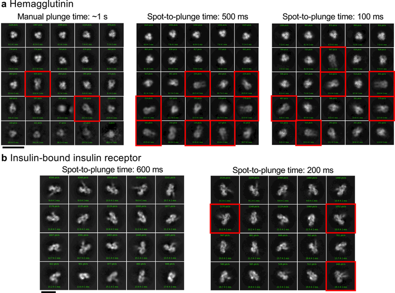
Single particle cryoEM 2D classification comparison between long and short spot-to-plunge times. (a) 2D classification of hemagglutinin plunged with a Gatan CP3 with an estimated blot-to-plunge time of ~1 s shows severe preferred orientation in the resulting 2D class averages, where only 4% of classes are side-views (red squares) (left). When plunged with a spot-to-plunge time of 500 ms, the percentage of side-views increases to 9% (middle). When plunged with a spot-to-plunge time of 100 ms, 19% of classes are side-views (right). (b) 2D classification of insulin-bound insulin receptor with a spot-to-plunge time of 600 ms (left) shows a well-populated, yet incomplete, set of particle views in the class averages. When plunged with a spot-to-plunge time of 200 ms, several additional side-views are recovered (red squares). Scale bars are 20 nm. For a (left), For c, n>10 independent experiments; (middle), n=3 independent experiments; (right), n=2 independent experiments. For b (left), n>10 independent experiments; (right), n=2 independent experiments.
Figure 2.
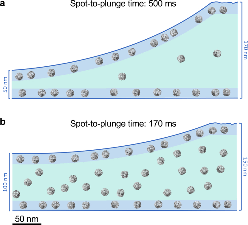
CryoET cross-sectional depictions of apoferritin comparing long and short spot-to-plunge times. Areas colored in blue represent locations where particles are adsorbed to the air-water interface while areas in teal represent the volume in between. (a) Apoferritin with 0.5 mM TCEP (15 mg/mL = 20,530 particle/μm3) plunged with a spot-to-plunge time of 500 ms shows that the vast majority of particles are adsorbed to air-water interfaces; the density of free-floating particles in the volume of ice is about 1,668 particles/μm3. (b) Apoferritin plunged with a spot-to-plunge time of 170 ms shows that while many particles are still adsorbed to air-water interfaces, the density of free-floating particles in the volume of ice increased by about 20x to 31,725 particles/μm3. For a, n>6 independent experiments. For b, n=2 independent experiments.
A shorter spot-to-plunge time of 100 ms for hemagglutinin results in much reduced preferred orientations (Fig. 1a), and results in a 3D reconstructed map at 3.8 Å (Supplementary Fig. 2) that is more isotropic and better resolved compared to the 4.2 Å map18 produced using grid tilt. Similarly, for the insulin-bound insulin receptor with a spot-to-plunge time of 200 ms, the reduced preferred orientation provides additional critical views of the complex (Fig. 1b), producing a 4.9 Å 3D reconstruction (Supplementary Fig. 3) that is of higher quality and more isotropic than that derived from images of tilted grids17. While the preferred orientation of hemagglutinin and insulin receptor were each significantly reduced with shorter spot-to-plunge times, the majority of particles still remained adsorbed to the air-water interfaces (Supplementary Videos 4 & 5). However, in the case of apoferritin with TCEP, a spot-to-plunge time of 170 ms vs. 500 ms significantly increased the density of non-adsorbed particles (Fig. 2b, Supplementary Video 6). The density of particles not adsorbed to the air-water interfaces increased by a factor of ~20x to about 31,725 particles/μm3 (Supplementary Fig. 4). When apoferritin at a lower concentration was prepared without TCEP (6 mg/mL = 8,212 particles/μm3 in solution), the density of non-adsorbed particles increased from about 3,043 particles/μm3 with a spot-to-plunge time of 500 ms to about 17,927 particles/μm3 with a spot-to-plunge time of 100 ms (Supplementary Figs. 5 & 6, Supplementary Videos 7 & 8). We note that there are far fewer particles adsorbed to the air-water interface for the apoferritin sample with TCEP added to the buffer but it is also likely that additional factors are contributing to the observed differences. These factors include effects of evaporation, estimated at 300 Å/s for (~85% relative humidity, ~70 °F). A full understanding of these and other effects clearly requires much further study under well-defined and controlled conditions.
These three example specimens show that deleterious effects of particle adsorption to air-water interfaces can be considerably reduced by decreasing the time between sample application and plunge-freezing, thus increasing the density of non-adsorbed particles in holes and reducing the opportunities for particles to equilibrate at air-water interfaces. We anticipate that the interface effects can be further reduced by decreasing the spot-to-plunge time even further, to a few 10s of msecs. The observations in this study do not directly address whether speeding up the plunging results in fewer particles being adsorbed to the air-water interface, but do clearly indicate that the overall effect is to reduce preferred orientation. In the case of Spotiton, faster spot-to-plunge times may be more challenging for controlling ice thickness and may require higher mesh grids (to increase nanowire density) or more accurate control of relative humidity. However, while thinner ice is usually the ideal outcome, we note that near-atomic resolution structures are attainable in ice thicker than 100 nm19. Finally, if the density of non-adsorbed particles can be significantly increased, performing per-particle CTF estimation20–22 on these images provides the possibility for in silico identification of non-adsorbed vs. adsorbed particles in single particle cryoEM. As a result, it may be possible to derive single particle cryoEM structures based only on non-adsorbed particles, thus allowing for more explicit studies of the effects of absorption on structure and preferred orientation.
METHODS
Methods, including statements of data availability and any associated accession codes and references, are available in the online version of the paper.
ONLINE METHODS
Sample preparation.
Hemagglutinin:
Hemagglutinin was prepared as described in Tan, Y. Z. et al., 201718.
Insulin-bound insulin receptor:
Insulin-bound insulin receptor was prepared as described in Scapin, G. et al., 201817.
Apoferritin:
Apoferritin from equine spleen (Sigma-Aldrich) as shown in Figure 2, Supplementary Figures 1 & 4, and Supplementary Videos 3 & 6 was prepared by diluting the stock sample to 15 mg/mL with 0.5 mM TCEP.
Apoferritin from equine spleen (Sigma-Aldrich) as shown in Supplementary Figures 5 & 6 and Supplementary Videos 7 & 8 was prepared as follows. 100 μL of sample at 25 mg/mL was diluted with 1 mL QA, 1 mL was loaded into a Q column, eluted with QB, and the main peak was pooled and concentrated to 0.5 mL. This 0.5 mL was then loaded onto a 10300 S200 column (GE) in QF, eluted at approximately 10.5 mL, and concentrated to working condition. [QA = 20 mM HEPES at pH 7.5, 0.1 mM EDTA at pH 8.0, 1 mM DTT; QB = QA + 1.5 M NaCl; QF = 150 mM NaCl, 20 mM HEPES at pH 7.5]
Grid preparation and vitrification:
Nanowire grids were prepared as described in Razinkov et al., 201614 and Wei et al., 201816. The samples were vitrified using the semi-automated Spotiton V1.0 robot, a novel device for preparing cryoEM samples using piezo dispensing to apply small (50 pL) drops of sample across a “self-blotting” nanowire grid as it flies past en route to plunge into liquid ethane. Nanowire grids, manufactured in-house, backed by lacey carbon film supports were used for all experiments. Nanowire grids were plasma cleaned for 10 secs (O2 + H2) using a Solarus 950 (Gatan, Inc.). Sample was dispensed onto a grid dropping vertically past the dispense head in 50 pL drops for a total of ~5 nL of sample applied as a stripe across the grid which was then plunged into liquid ethane. The time between sample application to the grid and plunging into liquid ethane (spot-to-plunge time) ranged from 100 to 800 ms. Spotiton was operated at ~85% relative humidity and ambient temperature (~70 °F). Under these conditions, evaporation is estimated to be 300 Å/s.
The time of flight of the 50 pL drops from the nozzle to the grid is estimated to be 0.5 ms and only the first drop has time to form a “skin” as it waits in the nozzle. Thus, this phase is likely unimportant in the formation of the air-water interface. After the first contact of drops to grid, the drops have a fairly large volume relative to surface area and spread out under their own momentum. Contact with the nanowires results in very rapid formation of a thin layer, estimated to occur within ~20 ms. We thus believe that most of the air-water interface effects occur in the time of flight between the formation of the thin layer and the plunge into ethane.
Single particle cryoEM data collection.
Hemagglutinin:
Single particle micrographs were collected on a Titan Krios (Thermo Fisher Scientific) equipped with an energy filter, Cs corrector, and a K2 counting camera (Gatan, Inc.); the microscope was operated at 300 kV at a nominal magnification of 130,000x, with a calibrated pixel size of 1.061 Å. Exposure was set to 10 secs (40 frames/image), for a total dose of 73.24 e–/Å2 with a defocus range of 1 to 2.1 μm. A total of 896 images were collected in three sessions using Leginon23.
Insulin-bound insulin receptor:
Single particle micrographs were collected on a Titan Krios (Thermo Fisher Scientific) equipped with an energy filter and a K2 BioQuantum counting camera (Gatan, Inc.); the microscope was operated at 300 kV at a nominal magnification of 105,000x, with a calibrated pixel size of 1.096 Å. Exposure was set to 10 secs (40 frames/image), for a total dose of 66 e–/Å2 with a defocus range of 1 to 2.5 μm. Collection was performed over three sessions using Leginon. For the 200 ms spot-to-plunge experiment, a total of 1,526 micrographs were used for single particle processing while 1,866 micrographs were used for the 800 ms spot-to-plunge experiment.
Single particle cryoEM data processing.
Hemagglutinin:
Frames were aligned using MotionCor224; global and per-particle CTF was estimated using gCTF20. Particle picking was performed using Gautomatch (http://www.mrc-lmb.cam.ac.uk/kzhang/) or DoG Picker25 followed by one round of 2D classification to remove false picks. A total of 104,365 particles were used for the final, symmetrized homogeneous 3D refinement in CryoSPARC26, producing a 3.77 Å map as shown in Supplementary Figure 2a.
Hemagglutinin with CP3:
The hemagglutinin dataset EMPIAR-10096 plunged with a Gatan CP3 from the paper Tan, Y. Z. et al., 201718 was used. From the 130,000 particle stack, a total of 15,000 particles were randomly selected for 2D classification and 3D refinement.
Insulin-bound insulin receptor:
Micrograph frames were aligned using MotionCor224; global and per-particle CTF was estimated using gCTF22. Particle picking was performed using Gautomatch (http://www.mrc-lmb.cam.ac.uk/kzhang/) followed by one round of 2D refinement to remove the false picks. Data processing from 2D classification through final reconstruction was performed using CryoSPARC as described in Scapin et al., 201817. The completeness of the maps was assessed the Euler angle orientation distribution as calculated by CryoSPARC and by evaluating each map’s directional FSC.
For the 200 ms spot-to-plunge experiment, a total of 83,513 particles were selected for ab-initio 3D classification from which the best 40,390 particles were used for the final, symmetrized homogeneous 3D refinement, producing a 4.93 Å map.
For the 800 ms spot-to-plunge experiment, a total of 276,466 particles were selected for ab-initio 3D classification from which the best 70,276 particles were used for the final, symmetrized homogeneous 3D refinement, producing a 6.09 Å map.
Tilt-series data collection.
Tilt-series were collected on a Titan Krios (Thermo Fischer Scientific) equipped with an energy filter and a K2 counting camera (Gatan, Inc.) and on a Tecnai F20 (Thermo Fischer Scientific) with a DE-20 camera (Direct Electron). Most tilt-series were collected nominally from −45° to 45° with 3° fixed or Saxton scheme27 increments using either Leginon23,28 or SerialEM29 with a nominal defocus near 5 microns, per-tilt image doses between 2 and 3 e-/Å2, and a pixel size of 2.16 Å (K2) and 2.34 Å (DE-20). K2 tilt images were whole-frame aligned using MotionCor2.
Tilt-series data processing.
Tilt-series were aligned with Appion-Protomo30,31 by first dose compensating the images with respect to the total accumulated dose32 of the tilt-series, coarse aligning tilt images, manually fixing coarse alignment if necessary, refining tilt-series alignment over several dozen iterations, and reconstructing with Tomo3D SIRT33,34. Tilt-series were not CTF corrected.
Tomogram particle picking.
Particles in the apoferritin tomograms (Supplementary Videos 3, 6, 7, & 8) were picked manually using Dynamo35. Particle picks were separated by location: 1) Particles over the carbon in the zero-degree projection direction or adsorbed to the carbon, 2) Particles adsorbed to the air-water interfaces in the grid holes, and 3) Non-adsorbed particles in the grid holes36. The particle picks and the resulting particle densities are shown in Supplementary Figures 1, 4, 5, & 6. Partial particles (where at least half of the particle is visible) were picked. The density of adsorbed particles was calculated by estimating the 2D surface area of each air-water interface and multiplying by the diameter of apoferritin to obtain the volume. We estimate that particle identification is accurate to within 1% and is complete to within 1% while volume measurements are estimated to be accurate to within 5% due to ice curvature and grid shape approximations, thus density calculations are likely accurate to within 5%. Density calculations were only performed on one tomogram (one location on the grid) per apoferritin grid, therefore while we estimate our counting accuracy for this one tomogram to be 5% it is clearly not applicable across the entire grid.
Data availability statement.
Single particle half maps, full sharpened maps, and masks for insulin-bound insulin receptor (200 ms spot-to-plunge time), insulin-bound insulin receptor (800 ms), and hemagglutinin (100 ms) have been deposited to the Electron Microscopy Data Bank (EMDB) with accession codes EMD-7788, EMD-7791, and EMD-7792, respectively. The full single particle collection of hemagglutinin (100 ms and 500 ms) has been deposited to the Electron Microscopy Pilot Image Archive (EMPIAR) with accession codes EMPIAR-10175 and EMPIAR-10197, respectively. Single particle cryoET tomograms have been deposited to the EMDB with accession codes EMD-7623, EMD-7624, EMD-7625, EMD-7150, EMD-7627, EMD-7628, EMD-7629, and EMD-7630. Single particle cryoET tilt-series, cryoET tilt-series alignment runs with Appion-Protomo, cryoET tomograms, and apoferritin particle picks have been deposited to the EMPIAR with accession codes EMPIAR-10169, EMPIAR-10170, EMPIAR-10171, EMPIAR-10141, EMPIAR-10172, EMPIAR-10129, EMPIAR-10173, and EMPIAR-10174.
Supplementary Material
ACKNOWLEDGEMENTS
The authors wish to thank Prof. Robert Glaeser at Lawrence Berkeley National Laboratory for helpful discussions, Dr. Kotaro Kelley at the New York Structural Biology Center (NYSBC) for apoferritin purification, and the Electron Microscopy Group at NYSBC for microscope calibration and assistance.
A.J.N. was supported by a grant from the NIH National Institute of General Medical Sciences (F32GM128303). Y.Z.T. was supported in part by the Agency for Science, Technology and Research Singapore. This work was performed at the Simons Electron Microscopy Center and National Resource for Automated Molecular Microscopy located at the New York Structural Biology Center, supported by grants from the Simons Foundation (SF349247), NYSTAR, and the NIH National Institute of General Medical Sciences (GM103310) with additional support from the Agouron Institute (F00316) and NIH (OD019994).
Footnotes
COMPETING FINANCIAL INTERESTS
B.C./C.S.P. have a commercial relationship with TTP Labtech, a company that will produce a commercially available Spotiton instrument.
References
- 1.Nogales E. The development of cryo-EM into a mainstream structural biology technique. Nature Methods (2015). doi: 10.1038/nmeth.3694 [DOI] [PMC free article] [PubMed] [Google Scholar]
- 2.Earl LA, Falconieri V, Milne JL & Subramaniam S. Cryo-EM: beyond the microscope. Curr. Opin. Struct. Biol. 46, 71–78 (2017). [DOI] [PMC free article] [PubMed] [Google Scholar]
- 3.Taylor KA & Glaeser RM Electron Diffraction of Frozen, Hydrated Protein Crystals. Science 186, 1036–1037 (1974). [DOI] [PubMed] [Google Scholar]
- 4.Adrian M, Dubochet J, Lepault J & McDowall AW Cryo-electron microscopy of viruses. Nature 308, 32–36 (1984). [DOI] [PubMed] [Google Scholar]
- 5.Kühlbrandt W. Biochemistry. The resolution revolution. Science 343, 1443–1444 (2014). [DOI] [PubMed] [Google Scholar]
- 6.Merk A. et al. Breaking Cryo-EM Resolution Barriers to Facilitate Drug Discovery. Cell 165, 1698–1707 (2016). [DOI] [PMC free article] [PubMed] [Google Scholar]
- 7.Noble AJ et al. Routine single particle CryoEM sample and grid characterization by tomography. eLife 7, e34257 (2018). [DOI] [PMC free article] [PubMed] [Google Scholar]
- 8.Glaeser RM & Han B-G Opinion: hazards faced by macromolecules when confined to thin aqueous films. Biophys. Rep. 3, 1–7 (2017). [DOI] [PMC free article] [PubMed] [Google Scholar]
- 9.Naydenova K & Russo CJ Measuring the effects of particle orientation to improve the efficiency of electron cryomicroscopy. Nat. Commun. 8, (2017). [DOI] [PMC free article] [PubMed] [Google Scholar]
- 10.Taylor KA & Glaeser RM Retrospective on the early development of cryoelectron microscopy of macromolecules and a prospective on opportunities for the future. J. Struct. Biol. 163, 214–223 (2008). [DOI] [PMC free article] [PubMed] [Google Scholar]
- 11.Feng X et al. A Fast and Effective Microfluidic Spraying-Plunging Method for High-Resolution Single-Particle Cryo-EM. Structure 25, 663–670.e3 (2017). [DOI] [PMC free article] [PubMed] [Google Scholar]
- 12.Ashtiani D. et al. Delivery of femtolitre droplets using surface acoustic wave based atomisation for cryo-EM grid preparation. J. Struct. Biol. 203, 94–101 (2018). [DOI] [PubMed] [Google Scholar]
- 13.Jain T, Sheehan P, Crum J, Carragher B & Potter CS Spotiton: A prototype for an integrated inkjet dispense and vitrification system for cryo-TEM. J. Struct. Biol. 179, 68–75 (2012). [DOI] [PMC free article] [PubMed] [Google Scholar]
- 14.Razinkov I. et al. A new method for vitrifying samples for cryoEM. J. Struct. Biol. 195, 190–198 (2016). [DOI] [PMC free article] [PubMed] [Google Scholar]
- 15.Dandey VP et al. Spotiton: New Features and Applications. (2018). doi: 10.1016/j.jsb.2018.01.002 [DOI] [PMC free article] [PubMed] [Google Scholar]
- 16.Wei H et al. Optimizing “self-wicking” nanowire grids. J. Struct. Biol. (2018). doi: 10.1016/j.jsb.2018.01.001 [DOI] [PMC free article] [PubMed] [Google Scholar]
- 17.Scapin G. et al. Structure of the Insulin Receptor–Insulin Complex by Single Particle CryoEM analysis. Nature (2018). doi: 10.1038/nature26153 [DOI] [PMC free article] [PubMed] [Google Scholar]
- 18.Tan YZ et al. Addressing preferred specimen orientation in single-particle cryo-EM through tilting. Nat. Methods 14, 793–796 (2017). [DOI] [PMC free article] [PubMed] [Google Scholar]
- 19.Rice WJ et al. Routine Determination of Ice Thickness for Cryo-EM Grids. bioRxiv 302018 (2018). doi: 10.1101/302018 [DOI] [PMC free article] [PubMed] [Google Scholar]
- 20.Zhang K Gctf: Real-time CTF determination and correction. J. Struct. Biol. 193, 1–12 (2016). [DOI] [PMC free article] [PubMed] [Google Scholar]
- 21.Grigorieff N, Grant T & Rohou A cisTEM: User-friendly software for single-particle image processing. bioRxiv 257618 (2018). doi: 10.1101/257618 [DOI] [PMC free article] [PubMed] [Google Scholar]
- 22.Hu M. et al. A particle-filter framework for robust cryoEM 3D reconstruction. bioRxiv 329169 (2018). doi: 10.1101/329169 [DOI] [PubMed] [Google Scholar]
- 23.Stagg S et al. Applications of Automated Electron Microscopy: Using Leginon to Study the Structure of COPII Protein Complexes. Microsc. Microanal. 11, 1072–1073 (2005). [Google Scholar]
- 24.Zheng SQ et al. MotionCor2: anisotropic correction of beam-induced motion for improved cryo-electron microscopy. Nat. Methods 14, 331–332 (2017). [DOI] [PMC free article] [PubMed] [Google Scholar]
- 25.Voss NR, Yoshioka CK, Radermacher M, Potter CS & Carragher B DoG Picker and TiltPicker: Software tools to facilitate particle selection in single particle electron microscopy. J. Struct. Biol. 166, 205–213 (2009). [DOI] [PMC free article] [PubMed] [Google Scholar]
- 26.Punjani A, Rubinstein JL, Fleet DJ & Brubaker MA cryoSPARC: algorithms for rapid unsupervised cryo-EM structure determination. Nat. Methods 14, 290–296 (2017). [DOI] [PubMed] [Google Scholar]
- 27.Saxton WO, Baumeister W & Hahn M Three-dimensional reconstruction of imperfect two-dimensional crystals. Ultramicroscopy 13, 57–70 (1984). [DOI] [PubMed] [Google Scholar]
- 28.Suloway C et al. Fully automated, sequential tilt-series acquisition with Leginon. J. Struct. Biol. 167, 11–18 (2009). [DOI] [PMC free article] [PubMed] [Google Scholar]
- 29.Mastronarde DN SerialEM: A program for automated tilt series acquisition on Tecnai microscopes using prediction of specimen position. Microsc. Microanal. 9, 1182CD (2003). [Google Scholar]
- 30.Noble AJ & Stagg SM Automated batch fiducial-less tilt-series alignment in Appion using Protomo. J. Struct. Biol. 192, 270–278 (2015). [DOI] [PMC free article] [PubMed] [Google Scholar]
- 31.Winkler H & Taylor KA Accurate marker-free alignment with simultaneous geometry determination and reconstruction of tilt series in electron tomography. Ultramicroscopy 106, 240–254 (2006). [DOI] [PubMed] [Google Scholar]
- 32.Grant T. & Grigorieff N. Measuring the optimal exposure for single particle cryo-EM using a 2.6 Å reconstruction of rotavirus VP6. eLife 4, e06980 (2015). [DOI] [PMC free article] [PubMed] [Google Scholar]
- 33.Agulleiro J-I & Fernandez J-J Tomo3D 2.0 – Exploitation of Advanced Vector eXtensions (AVX) for 3D reconstruction. J. Struct. Biol. 189, 147–152 (2015). [DOI] [PubMed] [Google Scholar]
- 34.Agulleiro JI & Fernandez JJ Fast tomographic reconstruction on multicore computers. Bioinforma. Oxf. Engl. 27, 582–583 (2011). [DOI] [PubMed] [Google Scholar]
- 35.Castaño-Díez D, Kudryashev M, Arheit M & Stahlberg H. Dynamo: A flexible, user-friendly development tool for subtomogram averaging of cryo-EM data in high-performance computing environments. J. Struct. Biol. 178, 139–151 (2012). [DOI] [PubMed] [Google Scholar]
- 36. Kremer JR, Mastronarde DN & McIntosh JR Computer Visualization of Three-Dimensional Image Data Using IMOD. J. Struct. Biol. 116, 71–76 (1996). [DOI] [PubMed] [Google Scholar]
Associated Data
This section collects any data citations, data availability statements, or supplementary materials included in this article.
Supplementary Materials
Data Availability Statement
Single particle half maps, full sharpened maps, and masks for insulin-bound insulin receptor (200 ms spot-to-plunge time), insulin-bound insulin receptor (800 ms), and hemagglutinin (100 ms) have been deposited to the Electron Microscopy Data Bank (EMDB) with accession codes EMD-7788, EMD-7791, and EMD-7792, respectively. The full single particle collection of hemagglutinin (100 ms and 500 ms) has been deposited to the Electron Microscopy Pilot Image Archive (EMPIAR) with accession codes EMPIAR-10175 and EMPIAR-10197, respectively. Single particle cryoET tomograms have been deposited to the EMDB with accession codes EMD-7623, EMD-7624, EMD-7625, EMD-7150, EMD-7627, EMD-7628, EMD-7629, and EMD-7630. Single particle cryoET tilt-series, cryoET tilt-series alignment runs with Appion-Protomo, cryoET tomograms, and apoferritin particle picks have been deposited to the EMPIAR with accession codes EMPIAR-10169, EMPIAR-10170, EMPIAR-10171, EMPIAR-10141, EMPIAR-10172, EMPIAR-10129, EMPIAR-10173, and EMPIAR-10174.