Abstract
1,8-Diiodooctane (DIO) is an additive used in the processing of organic photovoltaics and has previously been reported, on the basis of small-angle X-ray scattering (SAXS) measurements, to deflocculate nano-aggregates of [6,6]-phenyl-C71-butyric acid methyl ester (PC71BM) in chlorobenzene. We have critically re-examined this finding in a series of scattering measurements using both X-rays and neutrons. With SAXS, we find that the form of the background solvent scattering is influenced by the presence of DIO, that there is substantial attenuation of the X-rays by the background solvent and that there appears to be beam-induced aggregation. All three factors call into question the suitability of SAXS for measurements on these samples. By contrast, small-angle neutron scattering (SANS) measurements, performed at concentrations of 15 mg ml−1 up to and including 40 mg ml−1, show no difference in the aggregation state for PC71BM in chlorobenzene with and without 3% DIO; we find PC71BM to be molecularly dissolved in all solvent cases. In situ film thinning measurements of spin-coated PC71BM solution with the DIO additive dry much slower. Optical imaging shows that the fullerene films possess enhanced molecular mobility in the presence of DIO and it is this which, we conclude, improves the nanomorphology and consequently solar cell performance. We propose that any compatible high boiling solvent would be expected to show the same behaviour.
Keywords: polymer solar cell, fullerene, SAXS, SANS, morphology
1. Introduction
The addition of 1,8-diiodooctane (DIO) [1,2] (and other high boiling point additives [3]) to polymer–fullerene blends has a large influence on organic photovoltaic device performance and its use has enabled some of the highest efficiency devices observed at the time of writing [4]. Even now, as device scientists and engineers shift their focus to non-fullerene blend systems, the use of DIO in the casting solvent still persists and has very recently enabled a PCE over 13% to be achieved in a single junction organic solar cell [5]. There is, however, some ongoing debate in the field as to the exact role of DIO [6–11]. In particular, debate exists around its influence on the solution state of fullerenes such as [6,6]-phenyl-C71-butyric acid methyl ester (PC71BM) [12,13]. The primary role of DIO is to selectively dissolve one of the components of a polymer solar cell blend such that the film takes longer to form than it otherwise would with just a conventional solvent such as chlorobenzene. This extension in the drying time allows the bulk heterojunction nanostructure to evolve to give the appropriate length scales for solar cell device operation. A second suggested mode of action is to reduce the size of fullerene aggregates in solution prior to spin coating, as these could be detrimental to device performance by reducing the amount of interface within the device capable of extracting useful excitons. This second mechanism was proposed by Lou et al. [14] who examined the solution structure of PC71BM in chlorobenzene (CB) using small-angle X-ray scattering (SAXS) and found that the addition of a small amount of DIO (3% v/v) to CB altered the scattering signal of the fullerene solution. Their model-based analysis of the scattering data led them to interpret this as evidence that DIO improves the solubility of PC71BM when mixed with chlorobenzene. This reduction in the PC71BM aggregate size in solution was hypothesized to be the reason for improvement in OPV device efficiencies, when spin-coated with the polymer PTB7, as a result of improved intercalation of the fullerene. One of their main conclusions was that ‘While DIO molecules cause only slight changes in the size of the PTB7 aggregates in solution, they selectively and completely dissolve the PC71BM aggregates’ [14]. However, Das et al. [15] used small-angle neutron scattering (SANS) to study the solution state of PC71BM in pure dichlorobenzene (DCB) and in DCB with 3 wt% DIO. They concluded that there was no difference in the solution state of the PC71BM in DCB solution and that it was molecularly dissolved in both instances. In the light of contrary evidence, we set out to understand how DIO alters the solution behaviour of fullerenes in a simple fullerene solvent system and so decided to repeat these measurements. We have recently examined the drying behaviour of polymer blend devices using DIO and observed markedly different drying times for films with and without DIO [16]. We concluded [16], as had others [17], that nanostructure evolution during film drying was the main effect of adding DIO, but aimed to understand the action of DIO on fullerenes in solution more generally also.
2. Material and methods
For the SANS data presented in figures 5 and 6, we used 99% purity PC71BM. While for the SAXS data (figures 1–4; electronic supplementary material, figure S3) where we measured higher concentration solutions of PC71BM (40 mg ml−1), we used 95% purity PC71BM. All of the fullerene materials were purchased from Ossila, UK and are of high quality as evidenced by our ability to produce high-efficiency devices [16]. The solutions used in the SAXS and SANS experiments described here were prepared by dissolving the materials in chlorobenzene (99% purity) with/without 3% by volume DIO (98% purity), both purchased from Sigma–Aldrich.
Figure 5.
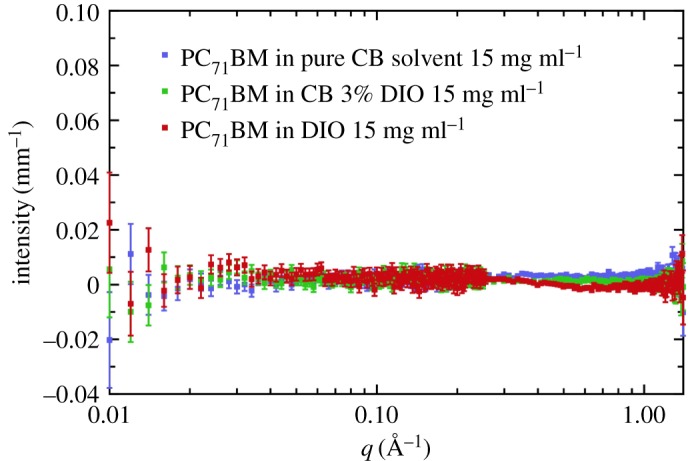
SANS solution data for PC71BM at a concentration of 15 mg ml−1 in pure chlorobenzene, chlorobenzene with 3% v/v DIO, and also in pure DIO.
Figure 6.
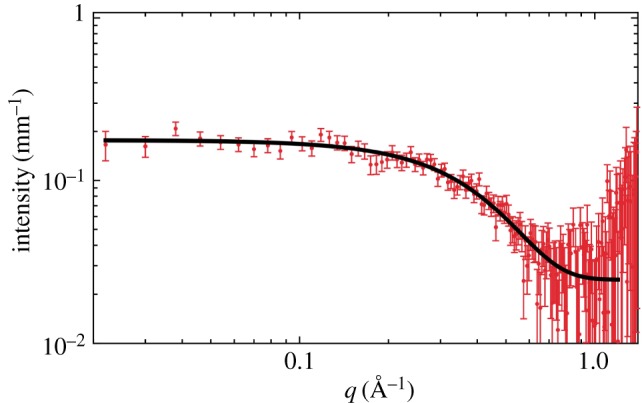
SANS solution data for PC71BM at a concentration of 15 mg ml−1 in pure carbon disulfide (CS2).
Figure 1.
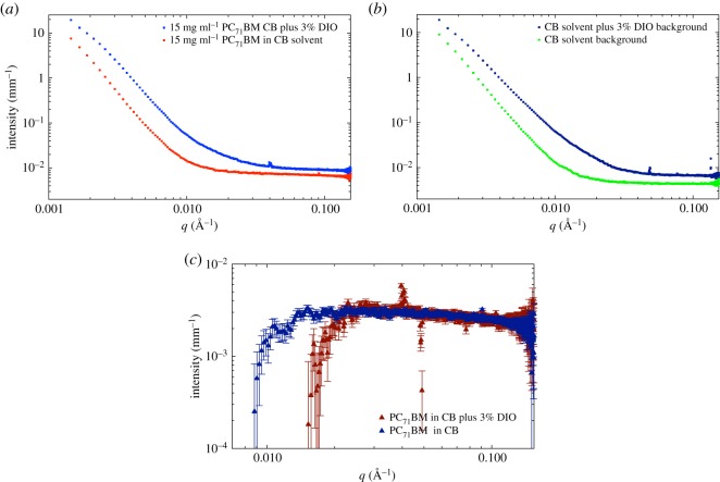
SAXS data for PC71BM (95% purity) at a concentration of 15 mg ml−1 in pure chlorobenzene and chlorobenzene with 3% v/v DIO (a) without background subtraction. (b) Scattering from the two respective background solvents, showing the large difference. (c) The solvent-subtracted SAXS data for the two cases of PC71BM with and without 3% v/v DIO.
Figure 2.
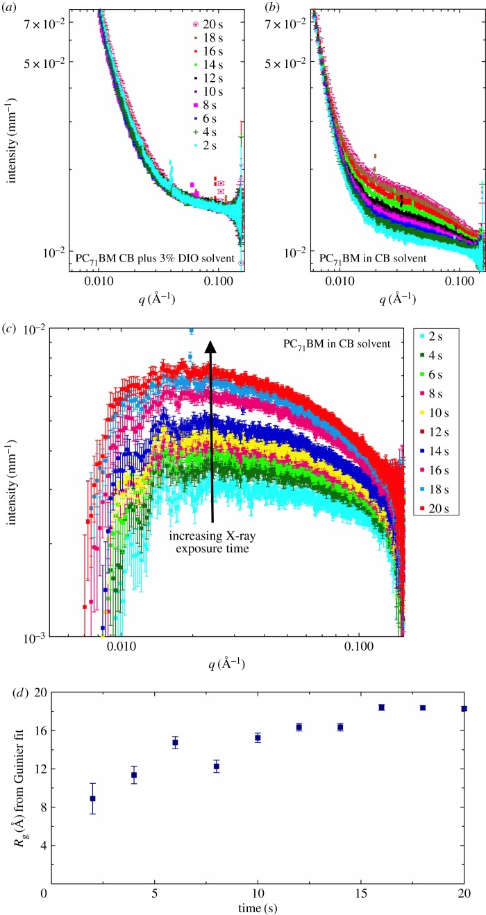
SAXS solution data for PC71BM (95% purity) solutions at a concentration of 15 mg ml−1 in (a) chlorobenzene with 3% v/v DIO and in (b) pure chlorobenzene. The result of solvent subtraction for (b) is shown in (c), and in (d), the shape-independent Guinier model-derived Rg as a function of cumulative SAXS exposure time.
Figure 3.
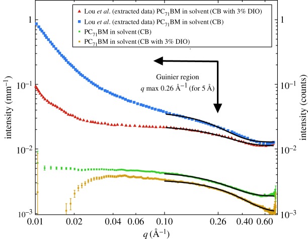
SAXS solution data for PC71BM at a concentration of 15 mg ml−1 in pure chlorobenzene and chlorobenzene with 3% v/v DIO. The data from the Lou et al. [14] paper have been extracted using GraphClick 3.0 to enable comparison with our own SAXS data.
Figure 4.
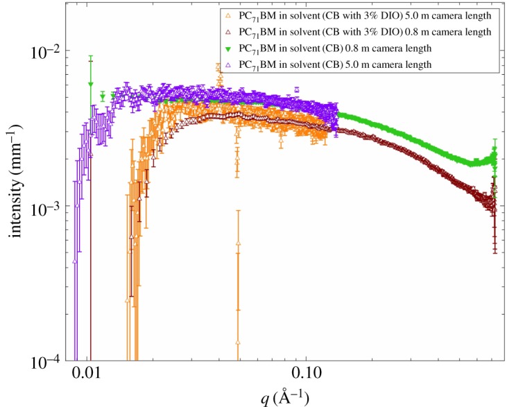
SAXS solution data for PC71BM at a concentration of 15 mg ml−1 in pure chlorobenzene, chlorobenzene with 3% v/v DIO for both camera distances (5 and 0.8 m) used in the SAXS measurements showing that the shape and overlap are consistent between the two measured q ranges used.
SAXS measurements were performed on the beamline ID02 at the ESRF (Grenoble, France) using an X-ray energy of 12.47 keV [18]. Samples were mounted in quartz capillaries nominally of 1.5 mm inner diameter (Capillary Tube Supplies Ltd, UK), though there is known to be some variation in the capillary diameter. To compensate for this, each capillary was individually measured and that diameter value was used to correct the data for path length. We had a measurement time of 2 s per frame. As we did not perform the experiment under flow, a fast shutter was employed with a closing time of 1.3 ms, to reduce the exposure of the solution over long periods (minutes) and to allow us to assess for beam damage. The X-ray beam spot size was 250 × 250 µm. The sample-to-detector distance was 5.0 m in figures 1 and 2 and 0.8 m in figure 3, and the same quartz capillaries and solutions were used for both sets of measurements. Data were recorded on a Rayonix MX-170HS detector, then normalized for transmission and reduced using the program SAXSutilities (http://www.sztucki.de/index_en.php) developed by Michael Sztucki (principally using the modules EDF plot and data tools to mask the beamstop and then perform radial integration) to give the one-dimensional scattering data, intensity versus q (where q = (4π/λ) sinθ, λ is the wavelength and 2θ is the scattering angle).
Further SAXS data were taken in a flow capillary geometry using a borosilicate glass capillary (Capillary Tube Supplies Ltd, UK) with a diameter of approximately 0.5 mm. This made possible measurements with a SAXS laboratory beamline using a liquid gallium MetalJet (Excillum) X-ray source (9.2 keV, λ = 1.34 Å). The scattered X-rays were detected using a Pilatus3 R 1M detector. The data were processed using Foxtrot software and scaling the data for transmission and thickness. Solvent subtractions were then performed using SASView.
SANS measurements were performed on the LOQ time-of-flight diffractometer at the ISIS Pulsed Neutron Source (Didcot, UK) [19]. The sample-to-detector distance was 4.1 m. Solutions were pipetted into PTFE-stoppered 1 mm pathlength quartz cuvettes (Hellma UK) that were mounted on a computer-controlled sample changer maintained at 25°C and data were recorded for approximately 90 min sample−1. The neutron beam diameter was 12 mm. Each raw scattering dataset was corrected for the incident neutron wavelength distribution, detector efficiency and spatial linearity, the measured transmission and cuvette pathlength, before being radially averaged and converted to coherent elastic scattering cross-section data (∂Σ/∂Ω) as a function of the scattering vector, q, using the Mantid framework [20]. Here, for convenience, we follow the normal convention of referring to ∂Σ/∂Ω as intensity, I. These reduced data were placed on an absolute scale by scaling to the scattering from a partially deuterated polymer blend of known molecular weight (which determines I(0)) measured under identical conditions, in accordance with established procedures [21].
The reduced SAXS or SANS from an empty capillary or cuvette, respectively, was then subtracted to yield data free of any scattering contribution from either the sample containers or the instrument. Volume fraction-adjusted proportions of the resulting solvent scattering data were then subtracted from the equivalent solution data.
The SAXS data from Lou et al. [14] (appearing in fig. 1b of that article) depicted in figure 3 here were extracted using the software GraphClick 3.0 (Arizona Software).
To enable the comparison of the relative scattering strength, we have calculated the scattering length densities for different X-ray energies and for neutrons. These were calculated using the NIST activation and scattering calculator (https://www.ncnr.nist.gov/resources/activation/).
For the in situ interferometric measurements, the substrates were single crystal silicon (Prolog Semicor Ukraine) spin-coated with a thin PEDOT : PSS (Clevios AI 4083) layer, 54 nm in thickness. The PC71BM was spin cast at a spin speed of 1500 r.p.m. Measurements of the film thinning dynamics were performed using the stroboscopic interference microscope set-up described in detail elsewhere [22,23]. Briefly, a small DC motor acts as a spin-coater, which is mounted directly under a 10× microscope objective. The current supply to the motor shows sharp dips as the brushes pass between the commutators and this is used to trigger both a 50 µs light pulse from a 620 nm LED (Luxeon Rebel Red) and image collection once per revolution. In our experimental geometry, the Bragg equation for constructive interference simplifies to d = mλ/3 (approximating polymer/solvent refractive indices to 1.5), where m is an integer value. Using near monochromatic illumination (λ = 620 nm, Δλ = 20 nm FWHM), constructive interference occurs as the film thins through every 206.67 nm. Drying curves were obtained through the application of an automated LabView fringe counting algorithm to a selected region across the field of view of the collected image sequences. These drying curves were placed on an absolute scale by adjusting their final end height to correspond to an area-averaged thickness of the final films obtained through ellipsometry.
The scanning probe microscopy measurements were carried out using a Dimension 3100 microscope in a tapping mode to measure the surface topography of the spin-coated films. The tapping tips had a resonance near 275 kHz.
3. Results and discussion
Solubility measurements have shown that PC71BM has an experimentally measured solubility limit of up to 210 mg ml−1 in chlorobenzene [24]. Consequently, it is reasonable to expect the fullerene to be molecularly dissolved in chlorobenzene solution at a concentration of 15 mg ml−1, given adequate preparation time. However, Lou et al. attributed the benefits of adding DIO to such a solution as promoting the deflocculation of PC71BM aggregates.
We performed a series of similar SAXS measurements on fullerene blends dissolved in halogenated solvents at an X-ray energy of 12.47 keV, very similar to the actual X-ray energy (13 keV) used by Lou et al. [14] (their paper incorrectly states 7 keV and has since been amended online; L. Chen 2017, personal communication). Our total q range (0.0015–0.7 Å−1) covers the entirety of the q-window studied in Lou et al.'s work [14] (0.01–0.7 Å−1; length scales of 628–9 Å), with our measurements also including larger structures out to 4188 Å.
Our SAXS data shown in figure 1 have been corrected for sample transmission and capillary thickness. The SAXS data prior to background subtraction are shown in figure 1a,b with and without DIO, respectively, while the data after solvent subtraction are shown in figure 1c. The first important point to note is that these are weakly scattering samples, that is, a small signal relative to the background solvent scatter. In figure 1b, we have plotted the respective solvents with and without the addition of DIO, observing a significant factor of 1.5 difference in the intensity of the background between the two solvents. However, more importantly, it is clear that the q-dependence of the scattering at q < 0.02 Å−1 is different for the two solvents. In other words, the intermediate-range molecular order in the two solvent systems (CB only and CB with DIO) appears to be different. In figure 1c, we plot the respective solvent-subtracted data for the case of PC71BM with and without DIO. This shows flat, featureless scattering, which diverges below a certain q value. This divergence is due to the over-subtraction of the background signal and probably arises for a number of reasons, including variations in the actual pathlength of the capillaries we used (1.5 mm), variations in the wall thickness of the capillaries (nominally 0.01 mm) and uncertainties in the calculation of the correct proportion of solvent scattering to subtract. Lou et al. [14] used a 1.5 mm pathlength flow cell which would have circumvented issues with pathlength variations.
In electronic supplementary material, figure S1, we plot the transmission values for all the solutions we have measured using SAXS. It can be seen that these values are very low because of the high electron density of both the Cl atoms, and especially the I atoms, which significantly attenuate the X-ray beam (the attenuation length of DIO—the pathlength needed to stop 1/e of the incoming beam is 89 µm at 12.47 keV and 100 µm at 13 keV; these values are about one-third that of aluminium), and in part because of the sample path lengths. The Beer–Lambert law tells us that thicker samples will have lower transmissions. Low transmission values can be indicative of multiple scattering effects, but also mean that a significant proportion of the energy of the incoming X-ray beam is being absorbed by the sample. The effect of so much energy flux being absorbed in such a small volume is likely to mean that the measurement cannot be assumed to be a passive one. There is a high probability that the beam may, in fact, induce aggregation and clustering of individual particles due to the photoelectrons released upon X-ray absorption [25]. To test this, in figure 2, we show the effect of exposure time (on successive frames) on the measured SAXS signal. With increasing X-ray exposure, the sample without DIO (figure 2b) displays an increase in the SAXS signal. This is not seen in the solvent (electronic supplementary material, figure S2) and so must come from the PC71BM, presumably due to X-ray-induced aggregation. Interestingly, this effect is not seen in the sample containing DIO in figure 2a.
To confirm our initial speculation that the X-ray beam is causing beam-induced aggregation of PC71BM, we fitted the SAXS data to a Guinier function over the range 0.02 Å−1 < q < 0.15 Å−1 using SasView 4.1 to obtain an effective Rg. These Rg values are shown in figure 2d as a function of time up to 20 s total beam exposure. Over this period, the Rg has more than doubled from 8 to 18 Å.
We also examined the high q data (q > 0.1 Å−1) taken at a camera length of 0.8 m, to more accurately look for differences in the Rg of the fullerene with and without the addition of DIO. The data are plotted in figure 3. What is clear is that our solution data have a reasonable Guinier plateau for both solvent cases, with minimal scattering at low q; this agrees well with our longer camera length SAXS data, which also plateaus in this q range. Fitting the data to a Guinier model for the region q = 0.1 Å−1 and above, we find, for the sample in CB only, that Rg is 6.1 ± 0.02 Å, and for the sample in CB with DIO Rg is 4.9 ± 0.02 Å. Performing the same fit to the extracted data of Lou et al. yields Rg values of 6.8 and 6.0 Å, respectively (but we obviously cannot estimate the uncertainties). These latter values are not dissimilar to our own, and rather less than the 11.5–12.6 Å reported by Lou et al., who chose to fit more complex multi-level empirical models for the case without DIO [14]. The overestimation of the Rg with Lou et al's use of these two models may be an artefact of incorrectly fitting the low-q data first in a multi-level model such as the unified fit, where the model should, by definition, be assembled by fitting the highest-q (smallest structural level) first and then progressing sequentially to larger and larger (lower-q) structures [26,27].
To further validate the Guinier plateau seen in the high q data (q > 0.1 Å−1) measured with a 0.8 m camera distance, we have plotted the data collected at both camera distances (5.0 and 0.8 m) in figure 4, where the shape and overlap are seen to be consistent. The presence of a Guinier plateau confirms that these are indeed isolated scatterers, with Rg values in the range 5–6 Å. But, a 12 Å Rg of the size modelled by Lou et al. would have a Guinier maximum q beginning at 0.108 Å−1, well within both q ranges for us to assess the size of any fullerene aggregates and model.
In contrast to SAXS, SANS is a much lower energy measurement. The energy of a 1 Å neutron is a little over 80 meV (cf. 12.4 keV for a 1 Å X-ray photon). The scattering/absorption of neutrons is also independent of the electron density of atoms. SANS data at the same q range (0.01–1 Å−1) as the data in figure 2 were collected, and the neutron transmission (electronic supplementary material, figure S4) through the solutions is ≥65% for 1 mm pathlength cuvettes (much greater than the X-ray transmission).
The SANS data are presented in figure 5 and show that in all cases, the scattering is flat and featureless. This indicates an absence of aggregates, or other structure, in the q range measured. We have verified that there is a sufficient neutron contrast in this solution system to be able to measure differences between the fullerene and the solvent (electronic supplementary material, tables S2 and S3). Consequently, we conclude that in all three of the solution cases considered (pure CB, pure DIO and CB with 3% DIO), the fullerene is molecularly dissolved.
We were unable to resolve the Rg for PC71BM in these solvents, due to a significant incoherent background component in these measurements (electronic supplementary material, table S2). To accurately measure the value for PC71BM, we have switched to the solvent carbon disulfide (CS2), which has been used previously to make OPV devices without the need for halogenated solvents [28]. Again using SANS and fitting a Guinier function, we measure an Rg value of 4.3 ± 0.1 Å (figure 6). This value compares well with the existing literature on C70, where previous SANS measurements on the fullerene C70 gave an Rg value of 4.13 ± 0.05 Å [29]. Another study again using CS2 demonstrated that SANS is sensitive to aggregates, in this instance for the fullerene C60, and the aggregates were attributed to differences in the preparation conditions, with 2 days dissolution time giving a solution free from aggregates [30].
We now shift our focus to what is happening to the PC71BM fullerene thin film layer as it dries. To understand the drying dynamics, in situ interferometry measurements were performed during spin coating [22,23]. Figure 7 shows the drying kinetics of the two fullerene solutions with the pure CB drying faster than when DIO is present. Ellipsometry was used to measure the final film thickness after spin coating. The solution without DIO gave a PC71BM film of 33 nm thickness, whereas the film cast from a solution in CB with 3% DIO was over three times thicker at 101 nm.
Figure 7.
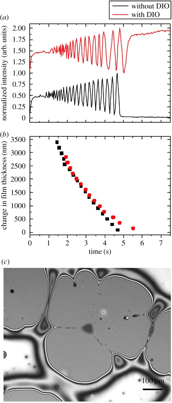
(a) Optical interference patterns showing the intensity changing as the film thins due to the process of evaporation. (b) The thickness change for the two solutions showing the divergence in the film drying dynamics. (c) Optical micrograph showing the surface of the spin-coated PC71BM thin film spun from CB with 3% v/v DIO.
Both solutions produced continuous films during the spin casting process; however, we see how mobile the thin film cast from CB with 3% DIO is based on the observation of film breakup and dewetting structures [31] for the PC71BM layer, sometime after spin coating (approx. 1 h). This confirms that there is indeed enhanced molecular mobility of the PC71BM due to the retained DIO in the thin film after the spin coating process has finished and the majority of the chlorobenzene has been removed. Critically, immediately after casting, the film was continuous as was the layer cast from pure CB, which remained continuous and free from dewetting features. The PC71BM CB 3% DIO film will be somewhat more solvated than the case when a conjugated polymer is present, as the overall solid concentration will be nearly double the pure fullerene case. After 24 h, the dewetted film processed from CB plus 3% DIO had a similar film colour and thickness showing that the DIO had been removed by evaporation [16]. Dewetting-type structures would not be helpful in a working solar cell device as it will cause a reduction in the active contact area of the electrodes, also it will deplete the fullerene from the cathode interface, which has previously been shown to provide higher efficiency devices [32]. The concept of additive-enhanced mobility in these systems as being the principal origin for morphology improvements in OPVs is fully consistent with the dynamics studies in the literature [33]. Recent dynamic measurements have concluded that additives are important as they inhibit large-scale liquid–liquid phase separation of polymer and fullerene, preventing the formation of large polymer and fullerene domains [34].
4. Conclusion
A prevalent assumption in the current literature is that the addition of DIO acts to improve performance in photovoltaic devices made from polymer–fullerene blend by dissolving or otherwise reducing the size of fullerene aggregates purported to exist in CB prior to spin coating. Unable to reproduce these observations, we carried out a full study aiming to understand the solution state of PC71BM in CB and CB with 3% DIO. Using both SAXS and SANS, we have shown that there is no change in the dissolution state of PC71BM upon the addition of DIO, and in fact, there is no aggregation of PCBM in solution with or without the additive, contrary to the analysis previously reported by Lou et al. [14]. Our SAXS and SANS measurements are in agreement and highlight the need for careful control of solvent backgrounds and absorption in such measurements, and that without careful control using either rapid exposures or flow, typical X-ray energies induce beam damage that appears consistent with unwanted aggregation. For both the solutions in CB only and CB with 3% DIO, we conclude that the PC71BM is molecularly dissolved. The combined use of the complementary techniques used in the present study casts considerable doubt upon this highly cited precedent in the literature [14]. Guinier analysis of the SAXS data in this work and the data extracted from the Lou et al. [14] paper are in agreement, showing that the fullerene is unchanged with and without DIO. Therefore, we conclude that the impact of the ‘additive’ DIO is that it resides in the film after the spin coating process has finished and allows enhanced molecular mobility of the DIO solvated fullerene on a much longer timescale than that of the rapid process of spin coating (figure 8). Formulation of polymer solar cell blends with suitable additives therefore relies on tailoring the additive to aid favourable morphology development during the extended drying phase [35]. Our results have important implications for device scientists and engineers attempting to maximize organic photovoltaic device quality and efficiency.
Figure 8.
A summary of our conclusions based on our SANS and SAXS measurements. The optical images on the right show the difference in the final pure PC71BM film morphology; with the presence of DIO the film we see dewetting structures.
Supplementary Material
Acknowledgements
We are grateful to the STFC and ISIS spallation neutron source for time on the SANS instrument Loq via experiments RB1620335 and RB1720412. The SANS data were reduced using the Mantid framework and analysed using the SasView application. SasView was originally developed under NSF award DMR-0520547 but contains code developed with funding from the European Union's Horizon 2020 research and innovation programme under the SINE2020 project, grant agreement no. 654000. We are grateful to Dr Mathew Derry for the assistance in measuring the SAXS data with RD at the ESRF. We thank Prof. Greg Beaucage for the input and feedback about the use and application of the unified fit model. GB is thankful to POCI-01-0145-FEDER-006939 (Laboratory for Process Engineering, Environment, Biotechnology and Energy–UID/EQU/00511/2013) funded by the European Regional Development Fund (ERDF), through COMPETE2020–POCI and by national funds, through FCT and NORTE-01-0145-FEDER-000005–LEPABE-2-ECO-INNOVATION, supported by North Portugal Regional Operational Programme (NORTE 2020), under the Portugal 2020 Partnership Agreement, through the European Regional Development Fund (ERDF).
Data accessibility
Data are available at the Dryad Digital Repository: (http://dx.doi.org/10.5061/dryad.553t5) [36]. The datasets supporting this article have been uploaded as part of the electronic supplementary material.
Authors' contributions
A.L.W. and J.P.A.F. modelled the X-ray absorption of chlorobenzene and stimulated the discussion for further SANS measurements. Y.Z. and G.B. made the samples. Y.Z., G.B., A.J.P. and S.M.K. measured the SANS data. A.J.P. reduced the SANS data. D.T.W.T., J.R.H. and A.J.P. performed the in situ spin coating experiments. A.J.P. recorded the optical images and the SPM data. R.D. carried out the SAXS measurements at the ESRF. All the authors were involved in the drafting, revision and approval of the submitted manuscript.
Competing interests
We have no competing interests.
Funding
G.B. was funded by an EU Horizon 2020 Marie Curie fellowship (grant agreement no. 658391). A.L.W. was funded by InnovateUK (33692-239251) and subsequently employed by the ISIS spallation neutron source. Y.Z. was funded by a Sheffield PhD studentship. S.M.K. is employed by the Science & Technology Facilities Council, a constituent body of UK Research & Innovation. D.T.W.T. was funded by EPSRC. R.D. was employed by ESRF. J.R.H., J.P.A.F. and A.J.P. are employed by The University of Sheffield, funded via HEFCE.
References
- 1.Sun Y, Welch GC, Leong WL, Takacs CJ, Bazan GC, Heeger AJ. 2012. Solution-processed small-molecule solar cells with 6.7% efficiency. Nat. Mater. 11, 44–48. ( 10.1038/nmat3160) [DOI] [PubMed] [Google Scholar]
- 2.Liao H-C, Ho C-C, Chang C-Y, Jao M-H, Darling SB, Su W-F. 2013. Additives for morphology control in high-efficiency organic solar cells. Mater. Today 16, 326–336. ( 10.1016/j.mattod.2013.08.013) [DOI] [Google Scholar]
- 3.Moon JS, Takacs CJ, Cho S, Coffin RC, Kim H, Bazan GC, Heeger AJ. 2010. Effect of processing additive on the nanomorphology of a bulk heterojunction material. Nano Lett. 10, 4005–4008. ( 10.1021/nl101923m) [DOI] [PubMed] [Google Scholar]
- 4.He Z, Xiao B, Liu F, Wu H, Yang Y, Xiao S, Wang C, Russell TP, Cao H. 2015. Single-junction polymer solar cells with high efficiency and photovoltage. Nature 9, 174–179. ( 10.1038/nphoton.2015.6) [DOI] [Google Scholar]
- 5.Cui Y, Yao H, Gao B, Qin Y, Zhang S, Yang B, He C, Xu B, Hou J. 2017. Fine-tuned photoactive and interconnection layers for achieving over 13% efficiency in a fullerene-free tandem organic solar cell. J. Am. Chem. Soc. 139, 7302–7309. ( 10.1021/jacs.7b01493) [DOI] [PubMed] [Google Scholar]
- 6.Lu L, Zheng T, Wu Q, Schneider AM, Zhao D, Yu L. 2015. Recent advances in bulk heterojunction polymer solar cells. Chem. Rev. 115, 12666–12731. ( 10.1021/acs.chemrev.5b00098) [DOI] [PubMed] [Google Scholar]
- 7.Zhang S, Ye L, Hou J. 2016. Breaking the 10% efficiency barrier in organic photovoltaics: morphology and device optimization of well-known PBDTTT polymers. Adv. Energy Mater. 6, 1502529-21 ( 10.1002/aenm.201502529) [DOI] [Google Scholar]
- 8.Zhang Y, Yuan J, Sun J, Ding G, Han L, Ling X, Ma W. 2017. Alkenyl carboxylic acid: engineering the nanomorphology in polymer–polymer solar cells as solvent additive. ACS Appl. Mater. Interfaces 9, 13396–13405. ( 10.1021/acsami.7b02075) [DOI] [PubMed] [Google Scholar]
- 9.Marinova N, Valero S, Delgado JL. 2017. Organic and perovskite solar cells: working principles, materials and interfaces. J. Colloid Interface Sci. 488, 373–389. ( 10.1016/j.jcis.2016.11.021) [DOI] [PubMed] [Google Scholar]
- 10.Lee J, Sin DH, Moon B, Shin J, Kim HG, Kim M, Cho K. 2017. Highly crystalline low-bandgap polymer nanowires towards high-performance thick-film organic solar cells exceeding 10% power conversion efficiency. Energy Environ. Sci. 10, 247–257. ( 10.1039/C6EE02466A) [DOI] [Google Scholar]
- 11.Holliday S, Li Y, Luscombe CK. 2017. Recent advances in high performance donor-acceptor polymers for organic photovoltaics. Prog. Polym. Sci. 70, 34–51. ( 10.1016/j.progpolymsci.2017.03.003) [DOI] [Google Scholar]
- 12.Kim W, Kim JK, Kim E, Ahn TK, Wang DH, Park JH. 2015. Conflicted effects of a solvent additive on PTB7:PC 71BM bulk heterojunction solar cells. J. Phys. Chem. C 119, 5954–5961. ( 10.1021/jp510996w) [DOI] [Google Scholar]
- 13.Kang H, Kim G, Kim J, Kwon S, Kim H, Lee K. 2016. Bulk-heterojunction organic solar cells: five core technologies for their commercialization. Adv. Mater. 28, 7821–7861. ( 10.1002/adma.201601197) [DOI] [PubMed] [Google Scholar]
- 14.Lou SJ, Szarko JM, Xu T, Yu L, Marks TJ, Chen LX. 2011. Effects of additives on the morphology of solution phase aggregates formed by active layer components of high-efficiency organic solar cells. J. Am. Chem. Soc. 133, 20661–20663. ( 10.1021/ja2085564) [DOI] [PubMed] [Google Scholar]
- 15.Das S, et al. 2015. Correlating high power conversion efficiency of PTB7:PC71BM inverted organic solar cells with nanoscale structures. Nanoscale 7, 15576–15583. ( 10.1039/C5NR03332B) [DOI] [PubMed] [Google Scholar]
- 16.Zhang Y, Parnell AJ, Pontecchiani F, Cooper JFK, Thompson RL, Jones RAL, King SM, Lidzey DG, Bernardo G. 2017. Understanding and controlling morphology evolution via DIO plasticization in PffBT4T-2OD/PC71BM devices. Sci. Rep. 7, 44269 ( 10.1038/srep44269) [DOI] [PMC free article] [PubMed] [Google Scholar]
- 17.Bokel FA, Engmann S, Herzing AA, Collins BA, Ro HW, DeLongchamp DM, Richter LJ, Schaible E, Hexemer A. 2017. In situ X-ray scattering studies of the influence of an additive on the formation of a low-bandgap bulk heterojunction. Chem. Mater. 29, 2283–2293. ( 10.1021/acs.chemmater.6b05358) [DOI] [Google Scholar]
- 18.Van Vaerenbergh P, Léonardon J. 2016. An upgrade beamline for combined wide, small and ultra small-angle X-ray scattering at the ESRF. In AIP Conference Proceedings, New York, NY, 6–10 July, AIP (American Institute of Physics). [Google Scholar]
- 19.Heenan RK, Penfold J, King SM. 1997. SANS at pulsed neutron sources: present & future prospects. J. Appl. Cryst. 30, 1140–1147. [Google Scholar]
- 20.Arnold O, et al. 2014. Mantid—data analysis and visualization package for neutron scattering and μ SR experiments. Nucl. Inst. Methods Phys. Res. A 764, 156–166. ( 10.1016/j.nima.2014.07.029) [DOI] [Google Scholar]
- 21.Wignall GDT, Bates FS. 1987. Absolute calibration of small-angle neutron scattering data. J. Appl. Crystallogr. 20, 28–40. ( 10.1107/S0021889887087181) [DOI] [Google Scholar]
- 22.Toolan DTW, Parnell AJ, Topham PD, Howse JR. 2013. Directed phase separation of PFO:PS blends during spin-coating using feedback controlled in situ stroboscopic fluorescence microscopy. J. Mater. Chem. A 1, 3587 ( 10.1039/c3ta01530k) [DOI] [Google Scholar]
- 23.Ebbens S, Hodgkinson R, Parnell AJ, Dunbar A, Martin SJ, Topham PD, Clarke N, Howse JR. 2011. In situ imaging and height reconstruction of phase separation processes in polymer blends during spin coating. ACS Nano 5, 5124–5131. ( 10.1021/nn201210e) [DOI] [PubMed] [Google Scholar]
- 24.Perea JD, et al. 2016. Combined computational approach based on density functional theory and artificial neural networks for predicting the solubility parameters of fullerenes. J. Phys. Chem. B 120, 4431–4438. ( 10.1021/acs.jpcb.6b00787) [DOI] [PubMed] [Google Scholar]
- 25.Martis V, Nikitenko S, Sen S, Sankar G, van Beek W, Filinchuk Y, Snigireva I, Bras W. 2011. Effects of X-rays on crystal nucleation in lithium disilicate. Crystal Growth Design 11, 2858–2865. ( 10.1021/cg200004y) [DOI] [Google Scholar]
- 26.Beaucage G. 1995. Approximations leading to a unified exponential/power-law approach to small-angle scattering. J. Appl. Crystallogr. 28, 717–728. ( 10.1107/S0021889895005292) [DOI] [Google Scholar]
- 27.Ilavsky J. Irena and Nika manuals 1.3.2 documentation: unified fit. https://saxs-igorcodedocs.readthedocs.io/en/stable/Irena/UnifiedFit.html. (accessed 25 August 2018).
- 28.Griffin J, Pearson AJ, Scarratt NW, Wang T, Dunbar ADF, Yi H, Iraqi A, Buckley AR, Lidzey DG. 2015. Organic photovoltaic devices with enhanced efficiency processed from non-halogenated binary solvent blends. Org. Electron. 21, 216–222. ( 10.1016/j.orgel.2015.03.019) [DOI] [Google Scholar]
- 29.Affholter KA, Henderson SJ, Wignall GD, Bunick GJ, Haufler RE, Compton RN. 1993. Structural characterization of C60 and C70 fullerenes by small-angle neutron scattering. J. Chem. Phys. 99, 9224–9229. ( 10.1063/1.465538) [DOI] [Google Scholar]
- 30.Avdeev MV, Tropin TV, Aksenov VL, Rosta L, Kholmurodov MT. 2008. Formation of fullerene clusters in carbon disulfide: data on small-angle neutron scattering and molecular dynamics. J. Synch. Investig. 2, 819–825. ( 10.1134/S1027451008060013) [DOI] [Google Scholar]
- 31.Geoghegan M, Krausch G. 2003. Wetting at polymer surfaces and interfaces. Prog. Polym. Sci. 28, 261–302. ( 10.1016/S0079-6700(02)00080-1) [DOI] [Google Scholar]
- 32.Staniec PA, et al. 2011. The nanoscale morphology of a PCDTBT: PCBM photovoltaic blend. Adv. Energy Mater. 1, 499–504. [Google Scholar]
- 33.Rogers JT, Schmidt K, Toney MF, Bazan GC, Kramer EJ. 2012. Time-resolved structural evolution of additive-processed bulk heterojunction solar cells. J. Am. Chem. Soc. 134, 2884–2887. ( 10.1021/ja2104747) [DOI] [PubMed] [Google Scholar]
- 34.van Franeker JJ, Turbiez M, Li W, Wienk MM, Janssen RAJ. 2015. A real-time study of the benefits of co-solvents in polymer solar cell processing. Nat. Commun. 6, 6229 ( 10.1038/ncomms7229) [DOI] [PubMed] [Google Scholar]
- 35.Richter LJ, DeLongchamp DM, Bokel FA, Engmann S, Chou KW, Amassian A, Schaible E, Hexemer A. 2015. In situ morphology studies of the mechanism for solution additive effects on the formation of bulk heterojunction films. Adv. Energy Mater. 5, 1400975 ( 10.1002/aenm.201400975) [DOI] [Google Scholar]
- 36.Bernardo G, et al. 2018. Data from: Does 1,8-diiodooctane affect the aggregation state of PC71BM in solution? Dryad Digital Repository. ( 10.5061/dryad.553t5) [DOI] [PMC free article] [PubMed]
Associated Data
This section collects any data citations, data availability statements, or supplementary materials included in this article.
Data Citations
- Bernardo G, et al. 2018. Data from: Does 1,8-diiodooctane affect the aggregation state of PC71BM in solution? Dryad Digital Repository. ( 10.5061/dryad.553t5) [DOI] [PMC free article] [PubMed]
Supplementary Materials
Data Availability Statement
Data are available at the Dryad Digital Repository: (http://dx.doi.org/10.5061/dryad.553t5) [36]. The datasets supporting this article have been uploaded as part of the electronic supplementary material.


