Abstract
New mesoporous silk fibroin (SF)/silica hybrids were processed via a one-pot soft and energy-efficient sol–gel chemistry and self-assembly from a silica precursor, an acidic or basic catalyst, and the ionic liquid 1-butyl-3-methylimidazolium chloride, acting as both solvent and mesoporosity-inducer. The as-prepared materials were obtained as slightly transparent-opaque, amorphous monoliths, easily transformed into powders, and stable up to ca. 300 °C. Structural data suggest the formation of a hexagonal mesostructure with low range order and apparent surface areas, pore volumes, and pore radii of 205–263 m2 g–1, 0.16–0.19 cm3 g–1, and 1.2–1.6 nm, respectively. In all samples, the dominating conformation of the SF chains is the β-sheet. Cytotoxicity/bioactivity resazurin assays and fluorescence microscopy demonstrate the high viability of MC3T3 pre-osteoblasts to indirect (≥99 ± 9%) and direct (78 ± 2 to 99 ± 13%) contact with the SF/silica materials. Considering their properties and further improvements, these systems are promising candidates to be explored in bone tissue engineering. They also offer excellent prospects as electrolytes for solid-state electrochemical devices, in particular for fuel cells.
Introduction
A considerable amount of the present research in the field of materials science combines bottom-up approaches and soft chemistry methods targeting the synthesis of sophisticated, recyclable, environmentally friendly, reliable, and low energy consuming bioinspired, and biomimetic synthetic materials.1−4 Countless natural systems display outstanding mechanical strength and toughness, as well as damage tolerance, which is often combined with self-repair capabilities.5 Bone,6 the abalone shell,7 the lobster cuticle,8 or the skeleton of sea sponges9−11 are a few examples of naturally occurring hierarchically structured nanocomposite materials encompassing exceptional performance. As a result, the elegance of protein-directed biomineralization processes toward high-performance hybrid materials has triggered tremendous interest in synthetic, yet bioinspired, biopolymer/mineral hybrid materials.1,12,13
Among natural polymers, silk is one of the most fascinating and versatile biomaterials. Silk exists in many variants made by different organisms, such as spiders and silkworms,14 and each variant is adapted to its specific purpose. Spider silk has attracted tremendous interest for application in (bio)materials science and related fields, mainly because of its outstanding mechanical and biological properties.14 However, because of its availability, Bombyx mori (silkworm) silk is the most widely investigated type of silk.15 Overall, silk has been extensively explored in various fields, but most of the research has been directed toward innovative applications in biomedical systems for drug delivery, enzyme immobilization, wound dressing, adhesive fillers, and tissue engineering.14,16 More recently, the use of silk in sustainable bio-inspired devices has raised considerable attention14,17−19 and applications of silk-based materials in optics,20−23 photonics,24 electronics,19,25−32 smart windows,32 and energy storage/conversion18,33−37 have emerged. Because of its outstanding mechanical properties, good biocompatibility, controlled biodegradability,38−42 and ease of processing into a wide variety of shapes (e.g., films, nanofibers, gels, hydrogels, scaffolds, micro- and nano-particles), silk has also been proposed as scaffold for bone tissue regeneration.43−45 Silk has, however, two major drawbacks that limit its application in the field of biomaterials:46−49 (1) it does not exhibit any osteoinductivity and (2) it has a nonideal osteoconductivity. These shortcomings can, for example, be overcome by association of silk with bioactive glasses (BGs).46−49
BGs are mainly silica-based biomaterials with osteoconductive, osteoproductive, and osteoinductive properties.50 The first attempt to prepare BGs by means of sol–gel chemistry was reported by Li et al.,51 20 years after Hench’s pioneering work,52 showing that the sol–gel method is a particularly attractive synthesis route. A judicious control of the sol–gel synthesis dictates whether the materials are xerogels, aerogels, or dense materials. This issue is a key parameter for BG design because high porosity and high surface area BGs induce high bone bonding rates and feature excellent degradation/resorption rates.53 A further advantage of the sol–gel process is that immobilization of biomolecules (e.g., proteins) or biological entities (e.g., cells) in silica matrices are possible, yielding bioactive organic/inorganic hybrid materials.54−56
The combination of sol–gel chemistry with supramolecular chemistry was the seed for the development of highly ordered mesoporous materials. It was immediately recognized that these materials are excellent candidates for implants with the ability to provide controlled and local drug delivery, or with improved bioactivity at the implant site.50,57 In particular, interconnected macroporosity within the 20–1000 μm range is mandatory in 3D scaffolds for bone tissue engineering58,59 to guarantee penetration, adherence, growth, and proliferation of bone cells (10–200 μm). Mesopores (2–50 nm diameter) are too small for cell uptake, but they are particularly suited for the locally controlled release of drugs in bone tissue (e.g., growth factors, antibiotics, chemotherapeutic agents, anti-oestrogens, and anti-inflammatory drugs), acting as attracting signals for bone cells. For example, Yan et al.60 demonstrated that highly ordered mesoporous bioglasses (MBGs) with improved surface area and pore volume exhibit significantly higher in vitro bone-forming bioactivity than regular BGs lacking mesopores. MBGs have, however, a series of disadvantages, including brittleness, high degradation rate, and surface instability. These factors compromise their mechanical strength and cytocompatibility and, therefore, limit clinical applications.
One way of overcoming the aforementioned problems is to adopt the organic/inorganic hybrid concept. To that end, the sol–gel reactions are carried out using inorganic MBG precursors in the presence of an appropriate organic co-component. The resulting organic/inorganic hybrid materials combine the benefits of MBGs with the features of the organic functionality, thus providing access to a wide range of attractive (bio)hybrid materials.61 In light of this successful strategy, the recent interest of the biomaterials community in silk/silica hybrid systems comes as no surprise.46−49,62−70
Wu et al.46 blended silk with MBG and concluded that silk addition improved the following: (1) the uniformity and continuity of the MBG pore network, while preserving high porosity (94%) and large pore size (200–400 μm); (2) the mechanical strength, mechanical stability, and control of burst release of dexamethasone; and (3) bone marrow stromal cell attachment, spreading, proliferation, and osteogenic differentiation on MBG scaffolds. In a subsequent study Wu et al.47 implanted MBG/silk and BG/silk scaffolds into calvarial defects in severe combined immunodeficient mice and evaluated the in vivo osteogenesis via microcomputed tomography, hematoxylin, eosin, and immunohistochemistry (type I collagen) analyses. The resulting MBG/silk scaffolds exhibited improved properties (e.g., mechanical strength, in vitro apatite mineralization, silicon (Si) ion release, and pH stability) with respect to BG/silk scaffolds. More recently Cheng et al.48 showed that MBG/silk scaffolds can be used as bone substitutes for local implantation into critical sized osteoporotic defects. The rapid mineralization and reduced osteoclastic activity on these MBG/silk scaffolds also suggested a therapeutic efficacy, especially in the site of post-menopausal osteoporosis.
A critical step in the synthesis of silk/silica hybrids is silk solubilization. To obtain homogeneous materials, silk needs to be dissolved in a suitable reaction medium;15 otherwise, macroscopic silk flakes with a silica coating are obtained rather than a true bioinspired hybrid material. Therefore, the dissolution of silk is the most critical obstacle in the synthesis process, as there are only very few solvents available for dissolving silk.71,72 Ionic liquids (ILs) emerged as a very attractive solution to circumvent this drawback. Some ILs dissolve silk73−76 and even silk/biopolymer composites.77 Moreover, apart from playing the role of solvents, ILs may also act as structure-directing agents. ILs may be viewed as supramolecular solvents with great potential for molecular recognition, self-assembly, and self-organization.78 The use of ILs is, thus, of the utmost interest, as they may provide access to new silk/silica hybrid materials that have not been accessible so far.
Motivated by the extraordinary versatility offered by ILs, we report in the present study a set of radically new mesoporous silk fibroin (SF)/silica hybrid materials prepared, for the first time, by means of a one-pot, soft sol–gel synthesis procedure, in which all of the precursor compounds co-exist in the same reaction medium. This new method relies on the following precursors: a Si source (tetramethylorthosilicate, TMOS), an acid or a base exerting the role of catalysts, and the IL 1-butyl-3-methylimidazolium chloride ([Bmim][Cl]) acting at the same time as adequate solvent for the SF79 and as template for the formation of the final mesoporous hybrid materials. It is noteworthy that the synthesis of the MBG/silk scaffolds discussed above involved a two-step procedure and required several compulsory compounds. These included a Si source (tetraethylorthosilicate), calcium source (calcium nitrate), phosphorous source (triethylphosphate), template (Pluronic P123) and solvent (ethanol). Wu et al.46 produced MBG scaffolds upon immersion of a Pluronic P123-containing solution in a polyurethane sponge, followed by evaporation of the excess solution and calcination. Silk/MBG scaffolds were then obtained through immersion of aqueous solutions of silk in the calcined MBG scaffolds, removal of the excess solution, and drying.46 Alternatively, MBG powders were produced from the above precursor solution via evaporation induced self-assembly, drying, and calcination.47,48 In the latter case, the final materials were prepared upon freeze-drying mixtures of the MBG powders uniformly dispersed in aqueous solutions of silk.47,48 The strategy proposed here is more environmentally friendly and more energy-efficient because it avoids the use of high-temperature (calcination) or low-temperature (freeze-drying) processes.
Results and Discussion
Hybrids Characterization
Figure 1 shows the physical appearance of the SF/hybrids. Scheme 1 shows the synthetic route and Table S1 summarizes the experimental conditions used for the synthesis of the SF/silica hybrids. The sol–gel reaction was performed in poly(propylene) (PP) tubes, which led to the tubular shape of the hybrids. All hybrids are quite hard, but brittle. H1, H3, and H4 are opaque and maintained their integrity after removal from the PP tube. H2 is slightly transparent and lost completely its integrity after removal from the PP tube; a similar behavior was observed for H3′ and H4′.
Figure 1.
Photographs of the SF/silica hybrids. The maximum length of the samples was approximately 1 cm.
Scheme 1. Scheme of the Synthesis of the SF/Silica Hybrids.
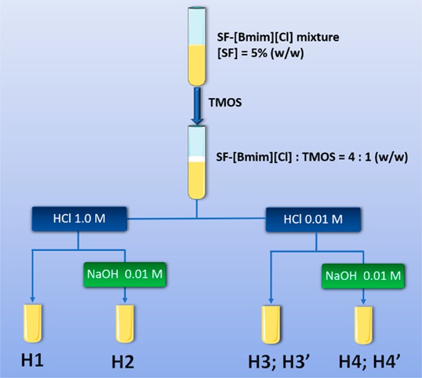
Cure time: 2 days for H1–H4, and 7 days for H3′ and H4′.
We may provide some tentative explanations for the breakdown of H2, H3′, and H4′. Comparison of the experimental conditions employed for the synthesis of samples H1, H2, and H4 (Table S1) leads us to suggest that the simultaneous use of a high concentration of HCl and the incorporation of NaOH may have caused the collapse of H2. The combined use of an acid and basic catalysts was expected to alter the kinetics of the sol–gel reactions (hydrolysis and condensation) of the TMOS precursor and ultimately affect the structure, morphology, and dimensional stability of the resulting material.80,81 In general, the condensation reactions are rate-limiting in acid medium and the hydrolysis reaction is rate-limiting in basic media.82 Comparison of the synthesis procedures employed for the preparation of H3, H4, H3′, and H4′ (Table S1) strongly suggests that the curing process, the final step of the synthesis, was too long in the case of the latter two samples, presumably leading to the formation of cracks and ultimately to the disintegration of the xerogels.
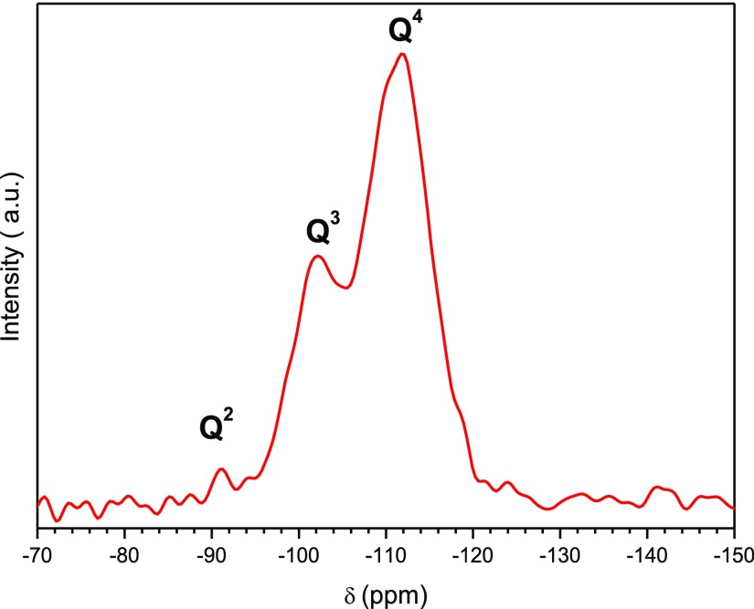
Figure 2 shows a representative 29Si magic angle spinning (MAS) nuclear magnetic resonance (NMR) spectrum of H3. The spectrum displays resonances between −80 and −130 ppm which are assigned to silicon sites Qx (Si(OSi)x(OR)4–x, where x is the number of Si–O–Si bonds. The NMR signals at −91.3, −101.8, and −111.7 ppm confirm the presence of Q2 (Si(OSi)2(OR)2), Q3 (Si(OSi)3OR), and Q4 (Si(OSi)4) (where R is H or CH3) environments. Their relative proportion was calculated by means of classical curve-fitting procedures assuming Gaussian shapes: ca. 1, 32, and 67%, respectively. The degree of condensation q (where q = 1/4 (1 × % Q1 + 2 × % Q2 + 3 × % Q3 + 4 × % Q4) deduced from the spectrum is 92%, indicating the formation of a three-dimensional silica network. This was essential to impart to the final hybrid materials high thermal stability, essentially amorphous nature and in particular good mechanical resistance to accommodate the pore structure.
Figure 2.
29Si MAS NMR spectrum of the H3 SF/silica hybrid.
Figure 3 shows typical scanning electron microscopy (SEM) images of samples H1 and H4′ demonstrating a rather coarse topography. SEM images obtained for the other samples are available in Figure S1. The corresponding elemental maps obtained from energy-dispersive X-ray (EDX) mapping confirm, however, a homogenous distribution of the organic (from the C and N maps) and inorganic (from the Si maps) components in both hybrid samples, at least on a micrometer length scale. SEM images of the other hybrids are similar (Figure S1).
Figure 3.
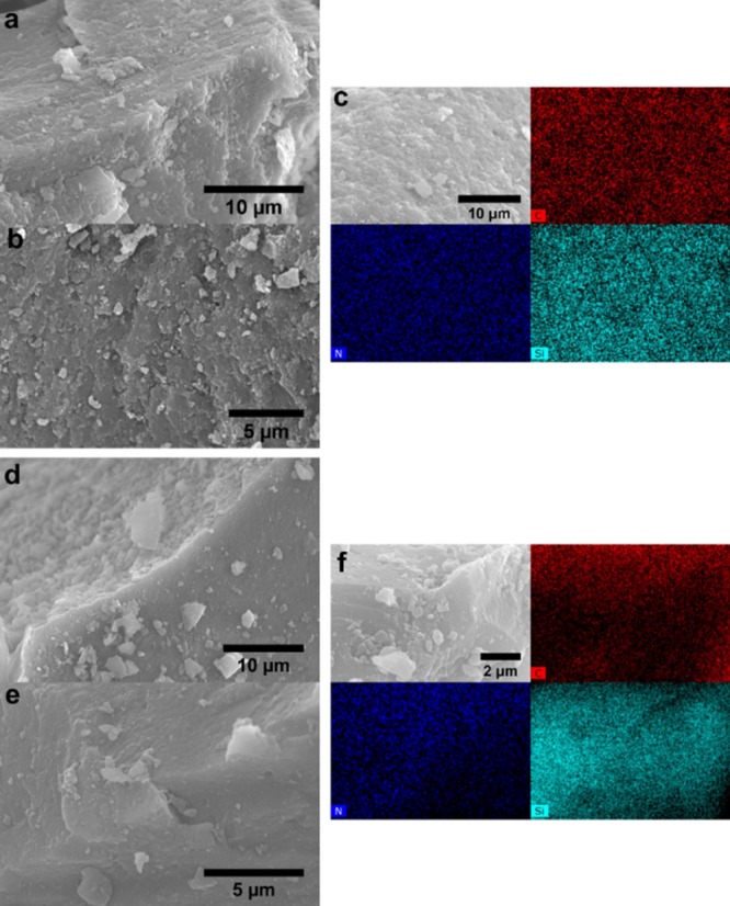
SEM images of selected hybrids H1 (a–c) and H4′ (d–f). Corresponding EDX mapping images of (cf) for C (red), N (navy blue), and Si (light blue) atoms.
Transmission electron microscopy (TEM) images of the hybrids (Figures 4 and S2) do not exhibit any of the typical features of mesostructuration. However, from a careful analysis of images such as that shown in the inset of Figure 4c, it is possible to identify a regular, ill-defined pattern, which may be associated with the typical one-dimensional channels of an ordered hexagonal arrangement. Unfortunately, the fast Fourier transform analysis is not conclusive and does not permit the estimation of a characteristic distance. The existence of small white spots in the TEM images is, however, indicative of the presence of pores in the SF/silica hybrids.
Figure 4.
TEM images of the H1 (a), H2 (b), and H4′ (c) SF/silica hybrids.
The nitrogen (N2) adsorption/desorption isotherms of the H1, H3, and H4 hybrids depicted in Figure 5 demonstrate reversible type IV behavior characteristic of mesoporous solids (pore size, i.e., distance between the two opposite walls, ranging between 2 and 50 nm, according to IUPAC classification).83 The shape of the adsorption/desorption hysteresis loops correlates with the texture (e.g., pore size distribution, pore geometry, and connectivity) of a mesoporous material.84 On the basis of the empirical classification of hysteresis loops given by IUPAC, we infer from Figure 5 that capillary condensation/evaporation between relative pressures above 0.4 induces a type H2 hysteresis loop in the three samples. H2-type loops are typical of disordered materials in which the distribution of pore size and shape is not well defined and is indicative of bottleneck constrictions.84
Figure 5.
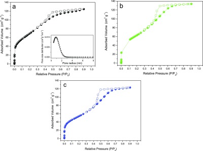
Nitrogen adsorption (closed squares)–desorption (open spheres) isotherms of the H1 (a), H3 (b), and H4, (c) SF/silica hybrids. Inset in (a): Pore size distribution plot obtained using the nonlocal density functional theory (NLDFT) model for the adsorption branch isotherm of H1.
The apparent Brunauer–Emmett–Teller (BET) surface areas, pore volumes, and pore radii of H1, H3, and H4 are 263, 240, and 205 m2 g–1, 0.16, 0.19, and 0.18 cm3 g–1 and 1.2, 1.6, and 1.6 nm, respectively. In the case of sample H2, the hysteresis of the desorption branch suggests that N2 cannot desorb from the pores (Figure S3). Moreover, the very low amount of adsorbed N2 (about 7.5 cm3 g–1) indicates that this sample is nonporous. The same behavior is observed in the adsorption/desorption isotherms of the hybrids H3′ and H4′ (not shown).
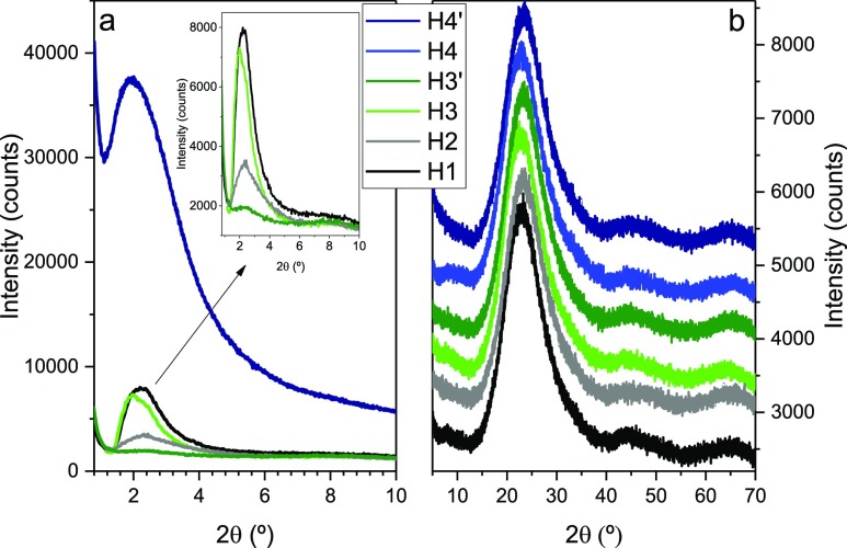
To try to rationalize these unexpected results, one needs to look on the N2 adsorption method itself. Porosity includes intra- and inter-particle porosity. Intraparticle porosity includes the open pores (i.e., cavities or channels that communicate with the surface of the particle) and closed pores (i.e., pores located inside the material). With N2 adsorption measurements, only open pores are determined. Open-ended pores and absence of pore networks are further assumed. Taking into account the limitations of the N2 adsorption method, we associate the low-angle peak observed in the powder X-ray diffraction (PXRD) patterns of H2 (gray line in Figure 6a) and H3′ (olive line in Figure 6a) with the presence of closed mesoporosity in the hybrid materials. The organosilica framework may have collapsed leading to the concomitant breakdown of the majority of open mesopores. The access of the N2 molecules may therefore have been blocked or considerably limited during the N2 adsorption measurements. This effect may explain the H2-type hysteresis adsorption/desorption loops found.
Figure 6.
PXRD patterns of selected SF/silica hybrids in the low- (a) and high- (b) angle regions.
In the low-angle range the PXRD patterns of the selected
hybrids
exhibits a single reflection (Figure 6a) centered at 1.38° (H3 and H4′), 1.59°
(H1), and 1.65° (H2). On the basis of the very high degrees of
condensation deduced from 29Si MAS NMR, pointing out the
presence of dominant Q4 sites, a lamellar
arrangement in the silica is highly unlikely. Further assuming that
our arguments on the existence of closed mesopores are true, this
peak is tentatively attributed to the (100) reflection of a (poorly)
ordered hexagonal mesostructure with a d(100) spacing of 6.40, 5.56, and 5.35 nm, respectively. The dimensions
of the hexagonal unit cell parameter a0 (defined as the internal pore diameter plus one pore wall width
and calculated using the equation  ) will then
be 7.39, 6.42, and 6.18 nm,
respectively. The marked attenuation of the low-angle reflections
in the PXRD patterns of all samples with respect to that of H4′
possibly indicates that the latter hybrid has a considerably higher
structural order than the former materials.
The lack of higher order reflection at higher 2θ values in all diffractograms indicates that the structural order does not extend over a long range and that it is rather low.
In the high-angle region, the PXRD patterns exhibit a broad and intense reflection centered at 23.3° and two considerably weaker, but again broad, reflections at 44.3° and 64.5° (Figure 6b). The reflection at 23.3° is characteristic of amorphous silica-based materials and may be attributed to ordering within the siloxane domains.85 The two weak reflections correspond to the second and third orders of the 23.3° peak. Unfortunately, the characteristic reflections of silk also fall in this range making the identification of the different silk conformations present impossible.86−89
Vibrational spectroscopy is a powerful tool to gain insight into the conformations and packing of polymer chains. The attenuated total reflection Fourier-transform infrared (ATR/FT-IR) spectra of the SF/silica hybrids are shown in Figure S4. The amide I (1700–1600 cm–1)90 and amide II (1600–1500 cm–1)90 spectral regions are particularly worthwhile analyzing to identify the conformational changes in the SF chains upon incorporation into the hybrid materials. The profile of the amide I and amide II bands of all samples display absorption maxima at approximately 1630 and 1528 cm–1. These wavenumbers are characteristic of SF chains along a β-sheet organization.91 For H2 and H4, shoulders are evident at 1658 and 1543 cm–1, pointing out the presence of random coils.
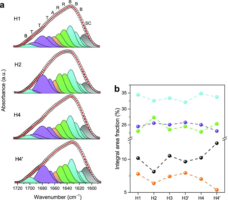
To gain additional insights into the details of the SF structure, curve-fitting of the amide I envelope was performed (Figure 7a). The amide I band was resolved into a series of components on the basis of the attribution proposed by Hu et al.91 Absorption bands in the 1605–1615 cm–1 interval are assigned to side chains; those from 1616–1637 to 1695–1705 cm–1 are assigned to ordered β-sheets, those in the 1638–1655 cm–1 range are representative of random coils, those in the 1656–1662 cm–1 range are assigned to α-helices, and those in the 1663–1696 cm–1 interval are assigned to turns.32,91 The integrated area fractions of the resolved individual components for each hybrid are shown in Figure 7b. On the basis of this analysis, the ordered β-sheet is clearly the most abundant conformation in all materials.
Figure 7.
Amide I region curve-fitting results of the ATR/FT-IR spectra of the SF/silica hybrids (a) and correspondent integral area fraction (b). Notation of the different contributions to the amide I envelope: random coils (R, green), β-sheets (B, cyan), α-helices (A, orange), turns (T, magenta), and side chains (SC, black).
The dominance of β-sheets is expected because the IL removal was performed with ethanol, and the immersion of silk materials in alcohols is known to promote the transition from disordered arrangements to ordered β-sheets.92 These data suggest that, globally, no major differences exist in terms of the relative amount of SF conformations in the hybrids, except for H2, which contains a slightly higher percentage of random coil conformations and a lower proportion of side chains and α-helices, and for H4′, which has more side chains but less α-helices.
It is of interest to recall at this stage that the loss of integrity of samples H2 and H4′ was correlated above with the high HCl concentration and high cure time employed in the synthesis, respectively. Again, these parameters might be the cause for the slight variations observed in terms of the relative conformations of SF chains. Overall, ATR/FT-IR therefore shows that the experimental conditions employed in the preparation of the hybrids did not induce significant differences in the silk protein conformations.
The amino acid composition of the heavy chain of SF is dominated by glycine (Gly), alanine (Ala), serine (Ser), and tyrosine (Tyr).14 The conformation-dependent chemical shifts of the 13C nuclei of these SF amino acids are local structure probes.93−96 The two main conformations usually reported for B. mori SF are often designated as silks I and II. Silk II (often addressed as β-sheet), the main conformation adopted after spinning, is characterized by the presence of an anti-parallel β-sheet structure, which is responsible for the excellent mechanical properties of silk fibers.14 Silk I forms before spinning and its structure is more controversial.95−98 However, it is accepted that random coil conformations and silk I give rise to the same 13C NMR chemical shifts.99−101
Figure 8 shows the 13C cross polarization (CP)/MAS NMR spectra of the SF/silica hybrids. The assignment of the most relevant resonances of the Ala, Gly, and Ser residues are indicated in Table S2. The 13C CP/MAS NMR data suggest that no significant differences exist in the SF/silica hybrids in terms of SF chain organization. In all cases, the dominant conformation present is the β-sheet. However, the heterogeneity due to the presence of other protein conformations in each sample is evident. These results are in perfect agreement with the ATR/FT-IR data discussed above. The case of H2 hybrid is useful to illustrate this. According to ATR/FT-IR, this sample contains a higher proportion of random coil conformations than all other materials of the series, a finding that is confirmed in the 13C CP/MAS NMR spectrum in the region characteristic of the Ala Cβ residue, in which the typical resonance of the silk I conformation is considerably more intense than that of the silk II conformation (marked with an arrow in Figure 8).
Figure 8.
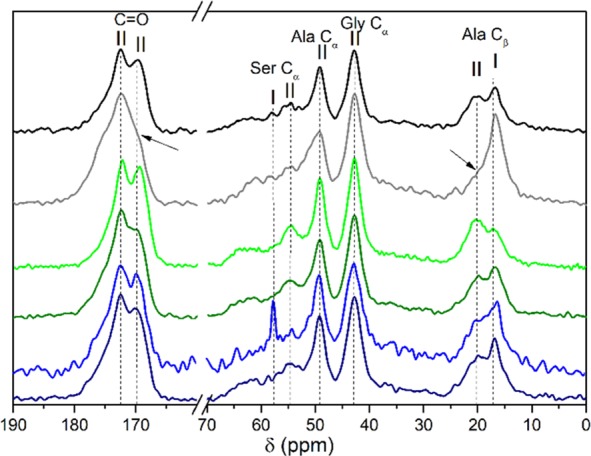
13C CP/MAS NMR spectra of the H1 (black line), H2 (gray line), H3 (green line), H3′ (olive line), H4 (blue line), and H4′ (navy line) SF/silica hybrids. Ala, Gly, and Ser indicate alanine, glycine, and serine, respectively, and I and II represent silk I and silk II conformations, respectively.
The thermogravimetric analysis (TGA) curves of the hybrids over the 30–900 °C range, shown in Figure 9, display different trends in the weight loss evolution. The weight losses can be separated into four main temperature ranges designated as regions I, II, III, and IV. At 150 °C (end of region I), the weight loss ranging from 0.8 to 2.2%, may be associated with the evaporation of residual solvents. The solvent content of the SF/silica hybrids follow the ascending order: H4 < H1 ≈ H3 < H2 < H4′ < H3′. In region II, a sharp weight loss, due to the thermal degradation of the SF chains, occurs.102 At 500 and 800 °C, the average weight loss is 19.4 and 30%, respectively. At 900 °C (region IV), about 31% of the materials remain. This residue is essentially silica. The weight loss is less pronounced for samples H2, H3′, and H4′.
Figure 9.
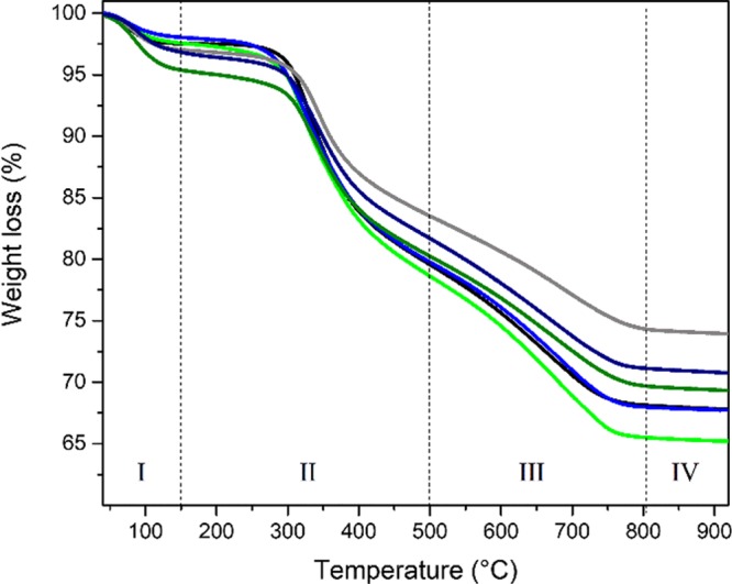
TGA curves of the H1 (black), H2 (gray), H3 (green), H3′ (olive), H4 (blue), and H4′(navy) hybrids.
Cytotoxicity and Bioactivity Tests
The cellular response of pre-osteoblasts (cell line MC3T3) to the hybrid materials was investigated to evaluate the cytotoxic response and the effect on bone cell behavior. MC3T3 cells were chosen to represent potential tissue in which the materials may interact during bone regeneration. As the cell response to a biomaterial can be affected by the material itself and the soluble species that may leach out from it, two different cytotoxicity methods were employed to assess the cell viability upon exposure to the SF/silica materials.
The cytotoxicity of the hybrids was investigated using the resazurin assay in two tests: one of the tests involved exposure to the hybrid through direct method, whereas the other test was carried out as an indirect method (Figure 10). Figure 10 clearly shows statistical differences between the cell viability of MC3T3 cells cultured with all hybrids, the blank culture minimum essential medium Eagle (MEM), and the cell viability of the cells exposed to the cytotoxic positive control. Following ISO 10993-5:2009 international standard, hydrogen peroxide was used as positive control.
Figure 10.
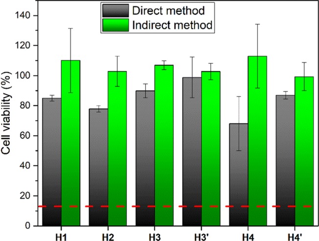
Cell viability rates of MC3T3 cells when exposed to SF/silica hybrids in direct and in indirect method. Horizontal red dashed line represents the value of cell viability for positive control (cytotoxic control).
The highest cell viability is observed in the indirect method tests with values as large as 110 ± 21% (Figure 10) for the MC3T3 cells cultured with the H1 hybrid. Nevertheless, all samples show quite high values of cell viability, the lowest values being 99 ± 9%. Statistically, there are no differences between samples. Cell viability levels were normalized using blank MEM (as negative control), making viability levels greater than 100% possible. The blank MEM corresponded to the cell culture medium [supplemented with 10% fetal bovine serum (FBS) and 1% penstrep] normally used for cell growing purposes. This means that the negative control was considered to be cells without being exposed to the SF/silica hybrid material, that is, cells with 100% viability.
In terms of the direct method test, all of the hybrids except H4 show high levels of cell viability, similar to the value presented with blank MEM (Figure 10), ranging from 78 ± 2 to 99 ± 13%. All results are statistically different from the cells cultured with the cytotoxic (positive) control (H2O2) which show 13% of viability (horizontal red dash line in Figure 10). Surprisingly H4 shows 68% of cell viability for the direct method test, suggesting that further analysis is needed to clarify this unusual behavior, especially in terms of the different physical interactions that may explain the influence on the cell mechanistics. The general trend of cell viability is lower in the direct method than in the indirect method test. This is expected because the direct placement of the hybrids on the cell monolayer increases the physical interaction with the cells and, therefore, increases the physical disruption and consequentially the cytotoxic impact.
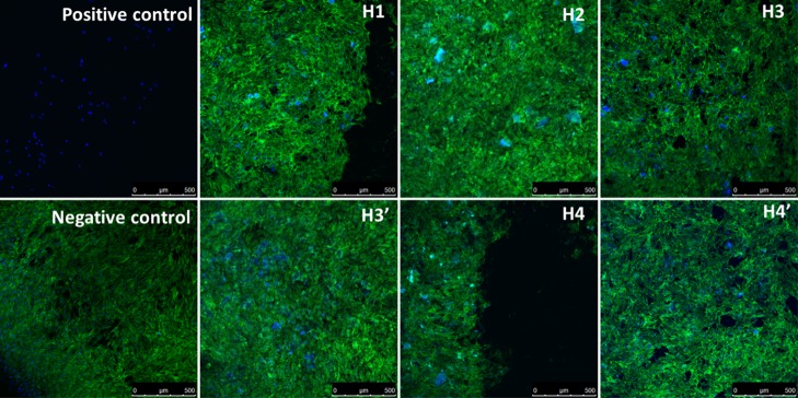
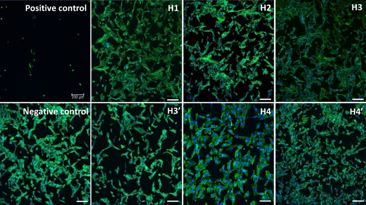
Fluorescence confocal imaging was used to confirm the resazurin assay results. No changes in cell morphologies are observed in the MC3T3 cells when exposed to the SF/silica hybrids, even when the materials are in direct method with the cells (except H4). Imaging of MC3T3 cells shows a normal, round shape, and confluent cell monolayer after direct and/or indirect methods with the materials (Figure 11). Moreover, there is no evidence of cell detachment and cell death (which is observed for cells exposed to the positive control). The only exception is H4 which shows some cell detachment, corroborating the previous results. Overall, the experiments show no changes in cell viability, phenotype, or detachment of the cells exposed to the hybrids or blank MEM, indicating that the materials could indeed find application as biomedical materials (Figure 12).
Figure 11.
Fluorescent confocal images of MC3T3 cells incubated by direct method for 24 h, with each SF/silica hybrids. F-actin morphology was study by staining cells as follows: 4′,6-diamidino-2-phenylindole (DAPI) (blue) stained nuclei, fluorescein isothiocyanate (FITC)-phalloidin (green) stained actin filaments, magnification 10×. Scale bar: 500 μm.
Figure 12.
Fluorescent confocal images of MC3T3 cells incubated by indirect method for 24 h, with each SF/silica hybrids. F-actin morphology was study by staining cells as follows: DAPI (blue) stained nuclei, FITC-phalloidin (green) stained actin filaments, magnification 10×. Scale bar: 200 μm.
Conclusions
[Bmim][Cl] is an efficient solvent and template for the fabrication of highly promising mesoporous SF/silica hybrid biomaterials with low range order but rather high surface areas. The synthesis strategy is based on the combination of soft and energy-efficient sol–gel and supramolecular chemistries where [Bmim][Cl] is responsible for the dissolution of SF and the formation of mesopores in the final materials. The cytotoxicity/bioactivity resazurin assays and fluorescence imaging demonstrate the high viability of the pre-osteoblast cell line MC3T3 to the as-prepared SF/silica hybrids both in indirect (at least 99 ± 9%) and direct (78–99%) methods. The present work opens new avenues into hybrid SF-based biomaterials with tunable morphology and mesoporosity induced through a judicious control of the IL size and type. We demonstrate that the concept introduced sets up a solid basis for future studies in bone tissue engineering. However, these new materials also lend themselves to applications in solid state electrochemistry, in particular for the development of composite electrolytes incorporating mesoporous channels acting as tunnels for fast proton conduction.
Experimental Section
Materials
TMOS (≥99.0%), anhydrous sodium carbonate (Na2CO3, 99.999%, Sigma-Aldrich), hydrochloric acid (HCl, 37%, Sigma-Aldrich), sodium hydroxide (NaOH, ≥98%, Sigma-Aldrich), and ethanol (p.a., absolute, ACS grade, Merck) were used as received. 1-Butyl-3-methylimidazolium chloride ([Bmim][Cl], 99%, IoLiTec Ionic Liquids Technologies GmbH) was stored under argon prior to use. SF was obtained by cutting B. mori cocoons (Aurora Silk, Portland, U.S.A.) into ca. 3 × 3 mm2 pieces. These were treated for 45 min in a boiling aqueous 0.02 M Na2CO3 solution. The as-prepared fibers were washed several times with distilled water and then dried in an oven at 50 °C.
Preparation of SF/Silica Hybrids
Purified SF fibers were dissolved in [Bmim][Cl]. To that end, dry SF was added stepwise to a flask containing molten [Bmim][Cl] at 80 °C under magnetic stirring to yield a 5.0% SF (w/w) solution which was stirred for 24 h under dynamic vacuum (10–3 mbar). The resulting homogenous solutions were transparent with a yellowish hue. No solid residue was observed.
Six SF/silica hybrids (H1, H2, H3, H3′, H4, and H4′) were synthesized by sol–gel chemistry (Scheme 1 and Table S1). Typically, about 1.7 g of the SF/[Bmim][Cl] solution was transferred to a PP tube (10 mL). Subsequently, TMOS was added under constant vortexing resulting in a reaction mixture of SF/[Bmim][Cl] solution/TMOS with a final weight ratio of 4:1. The resulting mixtures remained biphasic even after stirring for several hours, but upon addition of HCl (1 or 0.01 M), they became homogeneous after a few seconds. In the case of H2, H4, and H4′, NaOH (0.01 M) was then added to allow a faster network condensation. The resulting mixtures were then cured in an oil bath at 90 °C for 2 (H1, H2, H3, and H4) or 7 (H3′ and H4′) days. After cooling to ambient temperature, the IL was removed via Soxleth extraction with ethanol and the solid was subsequently dried at ambient temperature for at least 24 h. Attempts to produce control samples using the same reaction conditions employed to obtain the hybrids were not successful. When the precursor mixture was solely composed of TMOS and IL (absence of SF), no solid material was formed. When IL lacked in the reaction mixture composed of TMOS and SF, it was not possible to dissolve SF.
Characterization Methods
Powder X-ray Diffraction
PXRD data were collected in the 2θ range of 1°–10° and in the 2θ range of 4°–90° at ambient temperature using an Empyrean PANalytical diffractometer (Cu Kα1,2 X-radiation, λ1 = 1.540598 Å; λ2 = 1.544426 Å) with a PIXcel 1D detector and a flat-plate sample holder in transmission configuration (45 kV, 40 mA). Intensity data in the low angle region were collected by the step-counting method (step 0.01° or 0.0131°), in continuous mode, with the samples being prepared in the middle of two thin foil acetate films.
Thermogravimetric Analysis
TGA measurements were done on a PerkinElmer TGA 4000 thermal analyzer from ambient temperature to 900 °C at 10 °C min–1 under nitrogen atmosphere (50 mL min–1).
Nitrogen Sorption
N2 sorption experiments were performed on a Belsorp-Max, Bel Japan, Inc. Prior to analysis, samples were degassed at 160 °C for 12 h. The apparent BET surface areas were determined using the BET method in the 0.05–0.5 relative pressure range (p/p0). The surface area was calculated from the multipoint BET plot, and the pore volume was determined by the Barrett–Joyner–Halenda method. NLDFT pore size distributions were determined using the cylindrical pore model of the Belsorp-software.
Attenuated Total Reflection Fourier-Transform Infrared Spectroscopy
ATR/FT-IR spectra were measured on a Thermo Scientific Nicolet FT-IR Nexus 470 spectrometer equipped with an ATR bridge with a diamond crystal (Smart Orbit) and Omnic software package (version 8.1.11, Thermo Nicolet Fisher Scientific Inc.). Spectra were collected from 4000 to 400 cm–1 by averaging 64 scans at a resolution of 2 cm–1. Peak deconvolution was done with the nonlinear curve-fitting procedure as implemented by the PeakFit software.103 To automatically place hidden peaks, the residuals procedure was used. This procedure initially places peaks by finding local maxima in a smoothed data stream. Hidden peaks are then optionally added where peaks in the residuals occur. The best fit of the experimental data was obtained using Gaussian shapes and by varying the frequency, bandwidth, and intensity of the bands. A linear baseline correction with a tolerance of 0.2% was employed. The standard errors of the curve-fitting procedure were <0.03.
29Si MAS and 13C CP/MAS NMR Spectroscopy
29Si MAS and 13C CP/MAS NMR spectra were recorded on a Bruker AVANCE 400 (9.4 T) spectrometer at 79.49 and 100.62 MHz, respectively. 29Si MAS NMR spectra were recorded with 2 μs (θ ≈ 30) rf pulses, recycle delay of 60 s, and a 5.0 kHz spinning rate. 13C CP/MAS NMR spectra were recorded with 4 μs 1H 90° pulse, 2 ms contact time, a recycle delay of 4 s, and a spinning rate of 8 kHz. The chemical shifts (δ) are quoted in ppm using tetramethylsilane as internal standard.
Scanning Electron Microscopy
SEM images were obtained at 20 kV on a Hitachi S-3400N type II microscope equipped with a Bruker X-flash 5010 at high vacuum. Samples were sputter-coated with gold. Elemental mapping of the samples was performed by using the mapping option in the EDX analysis system. The acquisition time for a satisfactory resolution and noise performance was 1 min.
Transmission Electron Microscopy
TEM micrographs were obtained using a Hitachi H9000na microscope operated at 300 kV. Samples for TEM analysis were dispersed in ethanol and a drop of this suspension was deposited on a 400 mesh copper grid coated with a carbon film. Prior to TEM analysis the solvent was allowed to evaporate at ambient temperature.
Cytotoxicity and Bioactivity Tests
Cell Culture
Osteoblast MC3T3 cells (passages 16–21) were cultured at 37 °C in 5% CO2 in α-MEM, supplemented with 1% penicillin/streptomycin (Invitrogen Corp) and 10% FBS (Biowest).
Resazurin Assay
MC3T3 cells were harvested using 0.05% trypsin/ethylenediaminetetraacetic acid (EDTA) 1× before determining cell concentration using a hemocytometer. Cells were seeded in a 24 well tissue culture plate (Corning), with a cell density of 4 × 10⁴ cells/well and incubated for 24 h prior to the addition of the materials to allow proper adhesion. After this period, the medium was replaced by either 1 mL of medium containing the materials and/or their respective conditioned media (indirect method). Materials to be tested were weighted (12–16 mg) and added to their respective media to have a final concentration of 12 mg mL–1 cell incubation. For the indirect method, the same procedure was followed, although the respective materials were preincubated in cell medium at 37 °C in 5% CO2 for 24 h prior to cell addition (either in the direct/indirect methods). After 24 h of incubation and the medium removed, cells were washed thrice with 1× PBS, and 20% (v/v) of resazurin in medium (final volume of 1 mL) was added in each well, following the manufacturer protocol. The resulting solutions (aliquots of 100 μL) were transferred to a 96-well plate and the fluorescence measurements were performed with a fluorimeter (SynergyMx, BioTek) using a 560 nm excitation/590 nm emission filter set. Results are shown as the cell viability percentage with respect to the untreated cells (negative control). Hydrogen peroxide (Merck, 0.114%) was diluted in MEM and used as positive control, based on the international standard ISO 10993-5:2009, Biological evaluation of medical devices, Part 5: Tests for in vitro cytotoxicity.
Fluorescence Microscopy
For confocal microscopy (Leica, DMI6000B-CS), after 24 h exposure of the materials and/or the indirect method as described above, MEM was removed, and cells washed thrice with PBS 1×, before being fixed with 4% formalin solution neutral buffered for 20 min, permeabilised with 0.1% saponin (Sigma-Aldrich) for 5 min before staining the actin filaments using fluorescein-phalloidin (488 nm, Invitrogen Corp.), and the nucleus with DAPI (364 nm, Sigma-Aldrich). Images of the structure and organization of actin filaments (i.e., the cytoskeleton) and cell morphology/phenotype were acquired with a Leica TCS-SP5 AOBS confocal microscope. For multicolored microscopy, samples were excited with 364 and 488 nm laser lines, and images were captured by multitracking to avoid bleed-through between the fluorophores.
Acknowledgments
This work was supported by Fundação para a Ciência e a Tecnologia (FCT)/Deutscher Akademischer Austauschdienst (DAAD) Transnational Cooperation Project no. 6818 “Ionic liquid- and ionic liquid crystal-assisted formation of hybrid biomaterials scaffolds”. We further wish to thank the European Union, QREN, FEDER through “Programa Operacional Factores de Competitividade” (COMPETE), and CICECO—Aveiro Institute of Materials, POCI-01-0145-FEDER-007679 (FCT Ref. UID/CTM/50011/2013), financed by national funds through the FCT/MEC and when appropriate co-financed by FEDER under the PT2020 Partnership Agreement. This work was also funded by project UniRCell (POCI-01-0145-FEDER-016422 and SAICTPAC/0032/2015) financed by the European Regional Development Fund (ERDF) through COMPETE 2020, POCI and FCT. We also thank FCT in the framework of Strategic Funding UID/QUI/00686/2013 and UID/QUI/00686/2016, and funding under project PEst-OE/QUI/UI0616/2014. R.F.P.P. acknowledges FCT for a grant (SFRH/BPD/87759/2012).
Supporting Information Available
The Supporting Information is available free of charge on the ACS Publications website at DOI: 10.1021/acsomega.8b02051.
Relevant data of the synthesis of the SF/silica hybrids; additional SEM images of the hybrids; additional TEM images of the hybrids; nitrogen adsorption/desorption isotherms of the H2 hybrid; ATR/FT-IR spectra of the hybrids; and 13C CP/MAS NMR chemical shifts of the amino acid residues Ala, Gly, and Ser of the hybrids (PDF)
Author Contributions
The manuscript was written through contributions of all authors. All authors have given approval to the final version of the manuscript.
The authors declare no competing financial interest.
Supplementary Material
References
- Sanchez C.; Arribart H.; Giraud Guille M. M. Biomimetism and bioinspiration as tools for the design of innovative materials and systems. Nat. Mater. 2005, 4, 277–288. 10.1038/nmat1339. [DOI] [PubMed] [Google Scholar]
- Jabbari E.; Kim D.-H.; Lee L. P.; Ghaemmaghami A.; Khademhosseini A.. Biologically-Driven Engineering of Materials, Processes, Devices, and Systems; World Scientific: E-Book, 2014; p 1464. [Google Scholar]
- Bar-Cohen Y.Biomimetics—Nature Based Inovation; CRC Press: Boca Raton, Florida, 2011; p 512. [Google Scholar]
- Nosonovsky M.; Rohatgi P. K.. Biomimetics in Materials Science; Springer-Verlag: New York, 2012; p 418. [Google Scholar]
- D’Elia E.; Eslava S.; Miranda M.; Georgiou T. K.; Saiz E. Autonomous self-healing structural composites with bio-inspired design. Sci. Rep. 2016, 6, 25059. 10.1038/srep25059. [DOI] [PMC free article] [PubMed] [Google Scholar]
- Wegst U. G. K.; Bai H.; Saiz E.; Tomsia A. P.; Ritchie R. O. Bioinspired structural materials. Nat. Mater. 2015, 14, 23–36. 10.1038/nmat4089. [DOI] [PubMed] [Google Scholar]
- Srot V.; Wegst U. G. K.; Salzberger U.; Koch C. T.; Hahn K.; Kopold P.; van Aken P. A. Microstructure, chemistry, and electronic structure of natural hybrid composites in abalone shell. Micron 2013, 48, 54–64. 10.1016/j.micron.2013.02.010. [DOI] [PubMed] [Google Scholar]
- Nikolov S.; Petrov M.; Lymperakis L.; Friák M.; Sachs C.; Fabritius H.-O.; Raabe D.; Neugebauer J. Revealing the design principles of high-performance biological composites using ab initio and multiscale simulations: the example of lobster cuticle. Adv. Mater. 2010, 22, 519–526. 10.1002/adma.200902019. [DOI] [PubMed] [Google Scholar]
- Aizenberg J.; Sundar V. C.; Yablon A. D.; Weaver J. C.; Chen G. Biological glass fibers: Correlation between optical and structural properties. Proc. Natl. Acad. Sci. U.S.A. 2004, 101, 3358–3363. 10.1073/pnas.0307843101. [DOI] [PMC free article] [PubMed] [Google Scholar]
- Aizenberg J.; Weaver J. C.; Thanawala M. S.; Sundar V. C.; Morse D. E.; Fratzl P. Skeleton of Euplectella sp.: Structural hierarchy from the nanoscale to the macroscale. Science 2005, 309, 275–278. 10.1126/science.1112255. [DOI] [PubMed] [Google Scholar]
- Miserez A.; Weaver J. C.; Pedersen P. B.; Schneeberk T.; Hanlon R. T.; Kisailus D.; Birkedal H. Microstructural and Biochemical Characterization of the Nanoporous Sucker Rings fromDosidicus gigas. Adv. Mater. 2009, 21, 401–406. 10.1002/adma.200801197. [DOI] [Google Scholar]
- Sanchez C.; Belleville P.; Popall M.; Nicole L. Applications of advanced hybrid organic-inorganic nanomaterials: from laboratory to market. Chem. Soc. Rev. 2011, 40, 696–753. 10.1039/c0cs00136h. [DOI] [PubMed] [Google Scholar]
- Vallé K.; Belleville P.; Pereira F.; Sanchez C. Hierarchically structured transparent hybrid membranes by in situ growth of mesostructured organosilica in host polymer. Nat. Mater. 2006, 5, 107–111. 10.1038/nmat1570. [DOI] [PubMed] [Google Scholar]
- Pereira R. F. P.; Silva M. M.; de Zea Bermudez V. Bombyx moriSilk Fibers: An Outstanding Family of Materials. Macromol. Mater. Eng. 2015, 300, 1171–1198. 10.1002/mame.201400276. [DOI] [Google Scholar]
- Rockwood D. N.; Preda R. C.; Yücel T.; Wang X.; Lovett M. L.; Kaplan D. L. Materials fabrication from Bombyx mori silk fibroin. Nat. Protoc. 2011, 6, 1612–1631. 10.1038/nprot.2011.379. [DOI] [PMC free article] [PubMed] [Google Scholar]
- Kundu B.; Kurland N. E.; Bano S.; Patra C.; Engel F. B.; Yadavalli V. K.; Kundu S. C. Silk proteins for biomedical applications: Bioengineering perspectives. Prog. Polym. Sci. 2014, 39, 251–267. 10.1016/j.progpolymsci.2013.09.002. [DOI] [Google Scholar]
- Pal R. K.; Farghaly A. A.; Wang C.; Collinson M. M.; Kundu S. C.; Yadavalli V. K. Conducting polymer-silk biocomposites for flexible and biodegradable electrochemical sensors. Biosens. Bioelectron. 2016, 81, 294–302. 10.1016/j.bios.2016.03.010. [DOI] [PubMed] [Google Scholar]
- Jia X.; Wang C.; Zhao C.; Ge Y.; Wallace G. G. Toward Biodegradable Mg-Air Bioelectric Batteries Composed of Silk Fibroin-Polypyrrole Film. Adv. Funct. Mater. 2016, 26, 1454–1462. 10.1002/adfm.201503498. [DOI] [Google Scholar]
- Qi N.; Zhao B.; Wang S.-D.; Al-Deyab S. S.; Zhang K.-Q. Highly flexible and conductive composite films of silk fibroin and silver nanowires for optoelectronic devices. RSC Adv. 2015, 5, 50878–50882. 10.1039/c5ra03501e. [DOI] [Google Scholar]
- Lawrence B. D.; Cronin-Golomb M.; Georgakoudi I.; Kaplan D. L.; Omenetto F. G. Bioactive silk protein biomaterial systems for optical devices. Biomacromolecules 2008, 9, 1214–1220. 10.1021/bm701235f. [DOI] [PubMed] [Google Scholar]
- Perry H.; Gopinath A.; Kaplan D. L.; Dal Negro L.; Omenetto F. G. Nano- and micropatterning of optically transparent, mechanically robust, biocompatible silk fibroin films. Adv. Mater. 2008, 20, 3070–3072. 10.1002/adma.200800011. [DOI] [Google Scholar]
- Domachuk P.; Perry H.; Amsden J. J.; Kaplan D. L.; Omenetto F. G. Bioactive self-sensing optical systems. Appl. Phys. Lett. 2009, 95, 253702. 10.1063/1.3275719. [DOI] [PMC free article] [PubMed] [Google Scholar]
- Parker S. T.; Domachuk P.; Amsden J.; Bressner J.; Lewis J. A.; Kaplan D. L.; Omenetto F. G. Biocompatible silk printed optical waveguides. Adv. Mater. 2009, 21, 2411–2415. 10.1002/adma.200801580. [DOI] [Google Scholar]
- Amsden J. J.; Domachuk P.; Gopinath A.; White R. D.; Negro L. D.; Kaplan D. L.; Omenetto F. G. Rapid nanoimprinting of silk fibroin films for biophotonic applications. Adv. Mater. 2010, 22, 1746–1749. 10.1002/adma.200903166. [DOI] [PubMed] [Google Scholar]
- Omenetto F. G.; Kaplan D. L. A new route for silk. Nat. Photonics 2008, 2, 641–643. 10.1038/nphoton.2008.207. [DOI] [Google Scholar]
- Capelli R.; Amsden J. J.; Generali G.; Toffanin S.; Benfenati V.; Muccini M.; Kaplan D. L.; Omenetto F. G.; Zamboni R. Integration of silk protein in organic and light-emitting transistors. Org. Electron. 2011, 12, 1146–1151. 10.1016/j.orgel.2011.04.005. [DOI] [PMC free article] [PubMed] [Google Scholar]
- Müller C.; Hamedi M.; Karlsson R.; Jansson R.; Marcilla R.; Hedhammar M.; Inganäs O. Woven electrochemical transistors on silk fibers. Adv. Mater. 2011, 23, 898–901. 10.1002/adma.201003601. [DOI] [PubMed] [Google Scholar]
- Wang C.-H.; Hsieh C.-Y.; Hwang J.-C. Flexible organic thin-film transistors with silk fibroin as the gate dielectric. Adv. Mater. 2011, 23, 1630–1634. 10.1002/adma.201004071. [DOI] [PubMed] [Google Scholar]
- Ling S.; Li C.; Jin K.; Kaplan D. L.; Buehler M. J. Liquid exfoliated natural silk nanofibrils: Applications in optical and electrical devices. Adv. Mater. 2016, 28, 7783–7790. 10.1002/adma.201601783. [DOI] [PubMed] [Google Scholar]
- Omenetto F. G.; Kaplan D. L. New opportunities for an ancient material. Science 2010, 329, 528–531. 10.1126/science.1188936. [DOI] [PMC free article] [PubMed] [Google Scholar]
- Tao H.; Kaplan D. L.; Omenetto F. G. Silk Materials - A Road to Sustainable High Technology. Adv. Mater. 2012, 24, 2824–2837. 10.1002/adma.201104477. [DOI] [PubMed] [Google Scholar]
- Pereira R. F. P.; Sentanin F.; Pawlicka A.; Gonçalves M. C.; Silva M. M.; de Zea Bermudez V. Smart windows prepared from Bombyx mori silk. ChemElectroChem 2016, 3, 1084–1097. 10.1002/celc.201600095. [DOI] [Google Scholar]
- Romero I. S.; Bradshaw N. P.; Larson J. D.; Severt S. Y.; Roberts S. J.; Schiller M. L.; Leger J. M.; Murphy A. R. Biocompatible Electromechanical Actuators Composed of Silk-Conducting Polymer Composites. Adv. Funct. Mater. 2014, 24, 3866–3873. 10.1002/adfm.201303292. [DOI] [Google Scholar]
- Hou J.; Cao C.; Idrees F.; Ma X. Hierarchical porous nitrogen-doped carbon nanosheets derived from silk for ultrahigh-capacity battery anodes and supercapacitors. ACS Nano 2015, 9, 2556–2564. 10.1021/nn506394r. [DOI] [PubMed] [Google Scholar]
- Jia X.; Wang C.; Ranganathan V.; Napier B.; Yu C.; Chao Y.; Forsyth M.; Omenetto F. G.; MacFarlane D. R.; Wallace G. G. A Biodegradable Thin-Film Magnesium Primary Battery Using Silk Fibroin-Ionic Liquid Polymer Electrolyte. ACS Energy Lett. 2017, 2, 831–836. 10.1021/acsenergylett.7b00012. [DOI] [Google Scholar]
- Krüger S.; Schwarze M.; Baumann O.; Günter C.; Bruns M.; Kübel C.; Szabó D. V.; Meinusch R.; Bermudez V. Z.; Taubert A. Bombyx mori silk/titania/gold hybrid materials for photocatalytic water splitting: combining renewable raw materials with clean fuels. Beilstein J. Nanotechnol. 2018, 9, 187–204. 10.3762/bjnano.9.21. [DOI] [PMC free article] [PubMed] [Google Scholar]
- Pereira R. F. P.; Brito-Pereira R.; Gonçalves R.; Silva M. P.; Costa C. M.; Silva M. M.; de Zea Bermudez V.; Lanceros-Méndez S. Silk fibroin separators: A step toward lithium-ion batteries with enhanced sustainability. ACS Appl. Mater. Interfaces 2018, 10, 5385–5394. 10.1021/acsami.7b13802. [DOI] [PubMed] [Google Scholar]
- Jin H.-J.; Park J.; Karageorgiou V.; Kim U.-J.; Valluzzi R.; Cebe P.; Kaplan D. L. Water-Stable Silk Films with Reduced β-Sheet Content. Adv. Funct. Mater. 2005, 15, 1241–1247. 10.1002/adfm.200400405. [DOI] [Google Scholar]
- Winkler S.; Wilson D.; Kaplan D. L. Controlling β-Sheet Assembly in Genetically Engineered Silk by Enzymatic Phosphorylation/Dephosphorylation. Biochemistry 2000, 39, 12739–12746. 10.1021/bi001335w. [DOI] [PubMed] [Google Scholar]
- Matsumoto A.; Chen J.; Collette A. L.; Kim U.-J.; Altman G. H.; Cebe P.; Kaplan D. L. Mechanisms of Silk Fibroin Sol–Gel Transitions. J. Phys. Chem. B 2006, 110, 21630–21638. 10.1021/jp056350v. [DOI] [PubMed] [Google Scholar]
- Drummy L. F.; Farmer B. L.; Naik R. R. Correlation of the β-sheet crystal size in silk fibers with the protein amino acid sequence. Soft Matter 2007, 3, 877–882. 10.1039/b701220a. [DOI] [PubMed] [Google Scholar]
- Murphy A. R.; John P. S.; Kaplan D. L. Modification of silk fibroin using diazonium coupling chemistry and the effects on hMSC proliferation and differentiation. Biomaterials 2008, 29, 2829–2838. 10.1016/j.biomaterials.2008.03.039. [DOI] [PMC free article] [PubMed] [Google Scholar]
- Sofia S.; McCarthy M. B.; Gronowicz G.; Kaplan D. L. Functionalized silk-based biomaterials for bone formation. J. Biomed. Mater. Res. 2001, 54, 139–148. . [DOI] [PubMed] [Google Scholar]
- Altman G. H.; Diaz F.; Jakuba C.; Calabro T.; Horan R. L.; Chen J.; Lu H.; Richmond J.; Kaplan D. L. Silk-based biomaterials. Biomaterials 2003, 24, 401–416. 10.1016/s0142-9612(02)00353-8. [DOI] [PubMed] [Google Scholar]
- Wang Y.; Kim H.-J.; Vunjak-Novakovic G.; Kaplan D. L. Stem cell-based tissue engineering with silk biomaterials. Biomaterials 2006, 27, 6064–6082. 10.1016/j.biomaterials.2006.07.008. [DOI] [PubMed] [Google Scholar]
- Wu C.; Zhang Y.; Zhu Y.; Friis T.; Xiao Y. Structure-property relationships of silk-modified mesoporous bioglass scaffolds. Biomaterials 2010, 31, 3429–3438. 10.1016/j.biomaterials.2010.01.061. [DOI] [PubMed] [Google Scholar]
- Wu C.; Zhang Y.; Zhou Y.; Fan W.; Xiao Y. A comparative study of mesoporous glass/silk and non-mesoporous glass/silk scaffolds: Physiochemistry and in vivo osteogenesis. Acta Biomater. 2011, 7, 2229–2236. 10.1016/j.actbio.2010.12.019. [DOI] [PubMed] [Google Scholar]
- Cheng N.; Wang Y.; Zhang Y.; Shi B. The osteogenic potential of mesoporous bioglasses/silk and non-mesoporous bioglasses/silk scaffolds in ovariectomized rats: in vitro and in vivo evaluation. PLoS One 2013, 8, e81014. 10.1371/journal.pone.0081014. [DOI] [PMC free article] [PubMed] [Google Scholar]
- Mieszawska A. J.; Fourligas N.; Georgakoudi I.; Ouhib N. M.; Belton D. J.; Perry C. C.; Kaplan D. L. Osteoinductive silk-silica composite biomaterials for bone regeneration. Biomaterials 2010, 31, 8902–8910. 10.1016/j.biomaterials.2010.07.109. [DOI] [PMC free article] [PubMed] [Google Scholar]
- Arcos D.; Vallet-Regí M. Sol-gel silica-based biomaterials and bone tissue regeneration. Acta Biomater. 2010, 6, 2874–2888. 10.1016/j.actbio.2010.02.012. [DOI] [PubMed] [Google Scholar]
- Li R.; Clark A. E.; Hench L. L. An investigation of bioactive glass powders by sol-gel processing. J. Appl. Biomater. 1991, 2, 231–239. 10.1002/jab.770020403. [DOI] [PubMed] [Google Scholar]
- Hench L. L.; Splinter R. J.; Allen W. C.; Greenlee T. K. Bonding mechanisms at the interface of ceramic prosthetic materials. J. Biomed. Mater. Res. 1971, 5, 117–141. 10.1002/jbm.820050611. [DOI] [Google Scholar]
- Hamadouche M.; Meunier A.; Greenspan D. C.; Blanchat C.; Zhong J. P.; La Torre G. P.; Sedel L. Long-termin vivo bioactivity and degradability of bulk sol-gel bioactive glasses. J. Biomed. Mater. Res. 2001, 54, 560–566. . [DOI] [PubMed] [Google Scholar]
- Avnir D.; Braun S.. Biochemical Aspects of Sol-Gel Science and Technology; Springer US, 1996; p 144. [Google Scholar]
- Livage J.; Coradin T.; Roux C.. Bioactive sol-gel hybrids. In Functional Hybrid Materials; Gómez-Romero P., Sanchez C., Eds.; Wiley: Weinheim, 2005; pp 387–404. [Google Scholar]
- Nieto A.; Areva S.; Wilson T.; Viitala R.; Vallet-Regi M. Cell viability in a wet silica gel. Acta Biomater. 2009, 5, 3478–3487. 10.1016/j.actbio.2009.05.033. [DOI] [PubMed] [Google Scholar]
- Vallet-Regí M.; Balas F.; Arcos D. Mesoporous materials for drug delivery. Angew. Chem., Int. Ed. 2007, 46, 7548–7558. 10.1002/anie.200604488. [DOI] [PubMed] [Google Scholar]
- Hollister S. J. Porous scaffold design for tissue engineering. Nat. Mater. 2005, 4, 518–524. 10.1038/nmat1421. [DOI] [PubMed] [Google Scholar]
- Karageorgiou V.; Kaplan D. Porosity of 3D biomaterial scaffolds and osteogenesis. Biomaterials 2005, 26, 5474–5491. 10.1016/j.biomaterials.2005.02.002. [DOI] [PubMed] [Google Scholar]
- Yan X.; Yu C.; Zhou X.; Tang J.; Zhao D. Highly ordered mesoporous bioactive glasses with superior in vitro bone-forming bioactivities. Angew. Chem., Int. Ed. 2004, 43, 5980–5984. 10.1002/anie.200460598. [DOI] [PubMed] [Google Scholar]
- Gomez-Romero P.; Sanchez C.. Functional Hybrid Materials; Wiley-VCH: Weinheim, 2005; p 417. [Google Scholar]
- Hou A.; Chen H. Preparation and characterization of silk/silica hybrid biomaterials by sol-gel crosslinking process. Mater. Sci. Eng., B 2010, 167, 124–128. 10.1016/j.mseb.2010.01.065. [DOI] [Google Scholar]
- Huang L.; Wang H.; Hayashi C. Y.; Tian B.; Zhao D.; Yan Y. Single-strand spider silk templating for the formation of hierarchically ordered hollow mesoporous silica fibers. J. Mater. Chem. 2003, 13, 666–668. 10.1039/b212126c. [DOI] [Google Scholar]
- Foo C. W. P.; Patwardhan S. V.; Belton D. J.; Kitchel B.; Anastasiades D.; Huang J.; Naik R. R.; Perry C. C.; Kaplan D. L. Novel nanocomposites from spider silk–silica fusion (chimeric) proteins. Proc. Natl. Acad. Sci. U.S.A. 2006, 103, 9428–9433. 10.1073/pnas.0601096103. [DOI] [PMC free article] [PubMed] [Google Scholar]
- Xu Q.; Li J.; Peng Q.; Wu L.; Li S. Novel and simple synthesis of hollow porous silica fibers with hierarchical structure using silk as template. Mater. Sci. Eng., B 2006, 127, 212–217. 10.1016/j.mseb.2005.10.031. [DOI] [Google Scholar]
- Mieszawska A. J.; Nadkarni L. D.; Perry C. C.; Kaplan D. L. Nanoscale Control of Silica Particle Formation via Silk–Silica Fusion Proteins for Bone Regeneration. Chem. Mater. 2010, 22, 5780–5785. 10.1021/cm101940u. [DOI] [PMC free article] [PubMed] [Google Scholar]
- Belton D. J.; Mieszawska A. J.; Currie H. A.; Kaplan D. L.; Perry C. C. Silk-Silica Composites from Genetically Engineered Chimeric Proteins: Materials Properties Correlate with Silica Condensation Rate and Colloidal Stability of the Proteins in Aqueous Solution. Langmuir 2012, 28, 4373–4381. 10.1021/la205084z. [DOI] [PMC free article] [PubMed] [Google Scholar]
- Canabady-Rochelle L. L. S.; Belton D. J.; Deschaume O.; Currie H. A.; Kaplan D. L.; Perry C. C. Bioinspired silicification of silica-binding peptide-silk protein chimeras: Comparison of chemically and genetically produced proteins. Biomacromolecules 2012, 13, 683–690. 10.1021/bm201555c. [DOI] [PMC free article] [PubMed] [Google Scholar]
- Li C.; Hotz B.; Ling S.; Guo J.; Haas D. S.; Marelli B.; Omenetto F.; Lin S. J.; Kaplan D. L. Regenerated silk materials for functionalized silk orthopedic devices by mimicking natural processing. Biomaterials 2016, 110, 24–33. 10.1016/j.biomaterials.2016.09.014. [DOI] [PMC free article] [PubMed] [Google Scholar]
- Plowright R.; Dinjaski N.; Zhou S.; Belton D. J.; Kaplan D. L.; Perry C. C. Influence of silk-silica fusion protein design on silica condensation in vitro and cellular calcification. RSC Adv. 2016, 6, 21776–21788. 10.1039/c6ra03706b. [DOI] [PMC free article] [PubMed] [Google Scholar]
- Freddi G.; Pessina G.; Tsukada M. Swelling and dissolution of silk fibroin (Bombyx mori) in N-methyl morpholine N-oxide. Int. J. Biol. Macromol. 1999, 24, 251–263. 10.1016/s0141-8130(98)00087-7. [DOI] [PubMed] [Google Scholar]
- Cheng G.; Wang X.; Tao S.; Xia J.; Xu S. Differences in regenerated silk fibroin prepared with different solvent systems: From structures to conformational changes. J. Appl. Polym. Sci. 2015, 132, 41959. 10.1002/app.41959. [DOI] [Google Scholar]
- Phillips D. M.; Drummy L. F.; Conrady D. G.; Fox D. M.; Naik R. R.; Stone M. O.; Trulove P. C.; De Long H. C.; Mantz R. A. Dissolution and Regeneration ofBombyx moriSilk Fibroin Using Ionic Liquids. J. Am. Chem. Soc. 2004, 126, 14350–14351. 10.1021/ja046079f. [DOI] [PubMed] [Google Scholar]
- Phillips D. M.; Drummy L. F.; Naik R. R.; De Long H. C.; Fox D. M.; Trulove P. C.; Mantz R. A. Regenerated silk fiber wet spinning from an ionic liquid solution. J. Mater. Chem. 2005, 15, 4206–4208. 10.1039/b510069k. [DOI] [Google Scholar]
- Goujon N.; Wang X.; Rajkowa R.; Byrne N. Regenerated silk fibroin using protic ionic liquidssolvents: towards an all-ionic-liquid process for producing silk with tunable properties. Chem. Commun. 2012, 48, 1278–1280. 10.1039/c2cc17143k. [DOI] [PubMed] [Google Scholar]
- Silva S. S.; Popa E. G.; Gomes M. E.; Oliveira M. B.; Nayak S.; Subia B.; Mano J. F.; Kundu S. C.; Reis R. L. Silk hydrogels from non-mulberry and mulberry silkworm cocoons processed with ionic liquids. Acta Biomater. 2013, 9, 8972–8982. 10.1016/j.actbio.2013.06.044. [DOI] [PubMed] [Google Scholar]
- Silva S. S.; Santos T. C.; Cerqueira M. T.; Marques A. P.; Reys L. L.; Silva T. H.; Caridade S. G.; Mano J. F.; Reis R. L. The use of ionic liquids in the processing of chitosan/silk hydrogels for biomedical applications. Green Chem. 2012, 14, 1463–1470. 10.1039/c2gc16535j. [DOI] [Google Scholar]
- Antonietti M.; Kuang D.; Smarsly B.; Zhou Y. Ionic liquids for the convenient synthesis of functional nanoparticles and other inorganic nanostructures. Angew. Chem., Int. Ed. 2004, 43, 4988–4992. 10.1002/anie.200460091. [DOI] [PubMed] [Google Scholar]
- Pereira R. F. P.; Zehbe K.; Krüger S.; Silva M. M.; Salama A.; Hesemann P.; de Zea Bermudez V.; Taubert A.. Ionic liquids for the synthesis and design of hybrid biomaterials and interfaces. In Hybrid Organic-Inorganic Interfaces: Towards Advanced Functional Materials; Delville M. H., Taubert A., Eds.; Wiley-VCH: Weinheim, 2018; pp 581–636. [Google Scholar]
- Nunes S. C.; Hümmer J.; Freitas V. T.; Ferreira R. A. S.; Carlos L. D.; Almeida P.; de Zea Bermudez V. Di-amidosils with tunable structure, morphology and emission quantum yield: the role of hydrogen bonding. J. Mater. Chem. C 2015, 3, 6844–6861. 10.1039/c5tc00721f. [DOI] [Google Scholar]
- Pereira R. F. P.; Nunes S. C.; Toquer G.; Cardoso M. A.; Valente A. J. M.; Ferro M. C.; Silva M. M.; Carlos L. D.; Ferreira R. A. S.; de Zea Bermudez V. Novel highly luminescent amine-functionalized bridged silsesquioxanes. Front. Chem. 2018, 5, 131. 10.3389/fchem.2017.00131. [DOI] [PMC free article] [PubMed] [Google Scholar]
- Brinker C. J.; Scherer G. W.. The Physics and Chemistry of Sol-Gel Processing; Academic Press: San Diego, CA, 1990; p 912. [Google Scholar]
- Sing K. S. W. Reporting physisorption data for gas/solid systems with special reference to the determination of surface area and porosity (Recommendations 1984). Pure Appl. Chem. 1985, 57, 603–619. 10.1351/pac198557040603. [DOI] [Google Scholar]
- ALOthman Z. A review: Fundamental aspects of silicate mesoporous materials. Materials 2012, 5, 2874–2902. 10.3390/ma5122874. [DOI] [Google Scholar]
- Carlos L. D.; de Zea Bermudez V.; Sá Ferreira R. A.; Marques L.; Assunção M. Sol–Gel Derived Urea Cross-Linked Organically Modified Silicates. 2. Blue-Light Emission. Chem. Mater. 1999, 11, 581–588. 10.1021/cm980373n. [DOI] [Google Scholar]
- Jiang C.; Wang X.; Gunawidjaja R.; Lin Y.-H.; Gupta M. K.; Kaplan D. L.; Naik R. R.; Tsukruk V. V. Mechanical properties of robust ultrathin silk fibroin films. Adv. Funct. Mater. 2007, 17, 2229–2237. 10.1002/adfm.200601136. [DOI] [Google Scholar]
- Jin H.-J.; Kaplan D. L. Mechanism of silk processing in insects and spiders. Nature 2003, 424, 1057–1061. 10.1038/nature01809. [DOI] [PubMed] [Google Scholar]
- Kim U.-J.; Park J.; Joo Kim H.; Wada M.; Kaplan D. L. Three-dimensional aqueous-derived biomaterial scaffolds from silk fibroin. Biomaterials 2005, 26, 2775–2785. 10.1016/j.biomaterials.2004.07.044. [DOI] [PubMed] [Google Scholar]
- Zhang W.; Chen J.; Tao J.; Hu C.; Chen L.; Zhao H.; Xu G.; Heng B. C.; Ouyang H. W. The promotion of osteochondral repair by combined intra-articular injection of parathyroid hormone-related protein and implantation of a bi-layer collagen-silk scaffold. Biomaterials 2013, 34, 6046–6057. 10.1016/j.biomaterials.2013.04.055. [DOI] [PubMed] [Google Scholar]
- Miyazawa T.; Shimanouchi T.; Mizushima S.-i. Characteristic infrared bands of monosubstituted amides. J. Chem. Phys. 1956, 24, 408–418. 10.1063/1.1742489. [DOI] [Google Scholar]
- Hu X.; Kaplan D.; Cebe P. Determining beta-sheet crystallinity in fibrous proteins by thermal analysis and infrared spectroscopy. Macromolecules 2006, 39, 6161–6170. 10.1021/ma0610109. [DOI] [Google Scholar]
- Nogueira G. M.; Rodas A. C. D.; Leite C. A. P.; Giles C.; Higa O. Z.; Polakiewicz B.; Beppu M. M. Preparation and characterization of ethanol-treated silk fibroin dense membranes for biomaterials application using waste silk fibers as raw material. Bioresour. Technol. 2010, 101, 8446–8451. 10.1016/j.biortech.2010.06.064. [DOI] [PubMed] [Google Scholar]
- Hronska M.; van Beek J. D.; Williamson P. T. F.; Vollrath F.; Meier B. H. NMR Characterization of Native Liquid Spider Dragline Silk fromNephila edulis. Biomacromolecules 2004, 5, 834–839. 10.1021/bm0343904. [DOI] [PubMed] [Google Scholar]
- Asakura T.; Suzuki Y.; Nakazawa Y.; Yazawa K.; Holland G. P.; Yarger J. L. Silk structure studied with nuclear magnetic resonance. Prog. Nucl. Magn. Reson. Spectrosc. 2013, 69, 23–68. 10.1016/j.pnmrs.2012.08.001. [DOI] [PubMed] [Google Scholar]
- Asakura T.; Okushita K.; Williamson M. P. Analysis of the structure of Bombyx mori silk fibroin by NMR. Macromolecules 2015, 48, 2345–2357. 10.1021/acs.macromol.5b00160. [DOI] [Google Scholar]
- Asakura T.; Demura M.; Date T.; Miyashita N.; Ogawa K.; Williamson M. P. NMR study of silk I structure ofBombyx mori silk fibroin with15N- and13C-NMR chemical shift contour plots. Biopolymers 1997, 41, 193–203. . [DOI] [Google Scholar]
- He S.-J.; Valluzzi R.; Gido S. P. Silk I structure in Bombyx mori silk foams. Int. J. Biol. Macromol. 1999, 24, 187–195. 10.1016/s0141-8130(99)00004-5. [DOI] [PubMed] [Google Scholar]
- Lu Q.; Hu X.; Wang X.; Kluge J. A.; Lu S.; Cebe P.; Kaplan D. L. Water-insoluble silk films with silk I structure. Acta Biomater. 2010, 6, 1380–1387. 10.1016/j.actbio.2009.10.041. [DOI] [PMC free article] [PubMed] [Google Scholar]
- Asakura T.; Iwadate M.; Demura M.; Williamson M. P. Structural analysis of silk with 13C NMR chemical shift contour plots. Int. J. Biol. Macromol. 1999, 24, 167–171. 10.1016/s0141-8130(98)00082-8. [DOI] [PubMed] [Google Scholar]
- Asakura T.; Minami M.; Shimada R.; Demura M.; Osanai M.; Fujito T.; Imanari M.; Ulrich A. S. 2H-Labeling of Silk Fibroin Fibers and Their Structural Characterization by Solid-State2H NMR. Macromolecules 1997, 30, 2429–2435. 10.1021/ma9616726. [DOI] [Google Scholar]
- Demura M.; Minami M.; Asakura T.; Cross T. A. Structure ofBombyx moriSilk Fibroin Based on Solid-State NMR Orientational Constraints and Fiber Diffraction Unit Cell Parameters. J. Am. Chem. Soc. 1998, 120, 1300–1308. 10.1021/ja972069l. [DOI] [Google Scholar]
- Motta A.; Fambri L.; Migliaresi C. Regenerated silk fibroin films: Thermal and dynamic mechanical analysis. Macromol. Chem. Phys. 2002, 203, 1658–1665. . [DOI] [Google Scholar]
- PeakFit, 4.0; Systat Software, Inc.www.systat.com/products/PeakFit/.
Associated Data
This section collects any data citations, data availability statements, or supplementary materials included in this article.


