

Abstract
The highly fluorinated alkyl moieties of a new porphyrin drive the self-organization of thin films with C60 on ITO electrodes.
The supramolecular self-organization of porphyrin derivatives on conductive surfaces has been widely investigated1–7 because they are promising building blocks for the fabrication of photoactive materials. There are numerous studies on the spontaneous interactions between the pi system of the porphyrin macrocycle and the curved surface of a fullerene.8–10 The porphyrin–fullerene complexes are appealing as materials for solar-energy conversion and energy storage because they can form long-lived charge separated states. The large spherical shape and polarizability of C60 make it an excellent p-acceptor molecule.11 Moreover, because of the small reorganization energy involved in electron transfer reactions (ET), the charge transfer complex formed between C60 and a porphyrin can be remarkably stable.12 The oxidation and reduction potentials as well as the photophysical properties of porphyrins can be dictated by a variety of means such as metal coordination and exocyclic groups. While the porphyrin macrocycle is a good electron donor/acceptor, it is remarkably robust to oxidative damage, e.g. as films on surfaces.13 However, most of the exocyclic groups used to self-assemble and/or self-organize porphyrins can be oxidized, thus causing disassembly or reorganization of por phyrinic materials. Thus in applications wherein the nanoarchitecture of the chromophores is essential for the function of the materials, oxidation of the peripheral functional groups poses a limitation to their usefulness as a photoactive material. This latter consideration then limits the use of many porphyrinoid systems in photonic materials under ambient conditions.
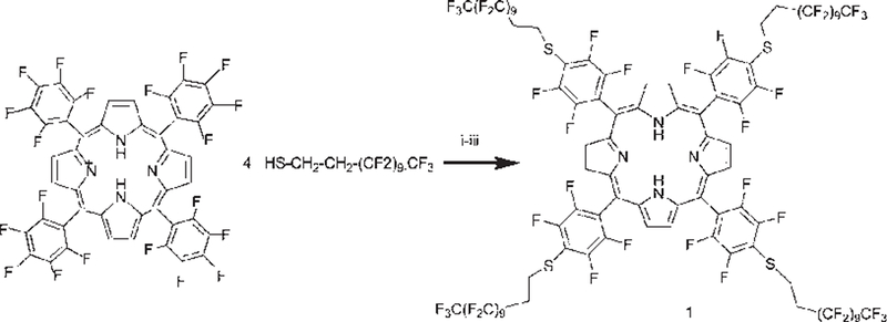
Herein the facile synthesis of a new highly fluorinated porphyrin that forms robust self-organized thin films with fullerene C60 on indium-tin-oxide coated glass is presented. The C–F bond imparts stability to the exocyclic groups, and the small polarizability of fluorine atoms confers a low surface energy to materials14 composed of this porphyrin. 5,10,15,20-Tetrakis[4-(1´H,1´H,2´- H, 2´H-perf luorododecyl) - 2, 3, 5, 6 - tetrafluorophenyl ] porphyrin (TPPF100) 1 is readily synthesized by reacting 5,10,15, 20-tetrakis(2,3,4,5,6-pentafluorophenyl)porphyrin (TPPF20) and 1H,1H,2H,2H-perfluorododecane-1-thiol (Scheme 1). The high yield and purity minimize the need for column chromatography. Compound 1 was crystallized from acetone in the form of purple hexagonal plates, in the triclinic crystal system, space group P-1 (Fig. 1).‡ This molecule has internal crystallographic symmetry. One half of the molecule is related to the other half by inversion symmetry. The strong intermolecular forces between the fluorinated alkanes appended to the porphyrin mediate the formation of a densely packed material as seen in the packing diagram. Similar dispersion interactions allow formation of robust thin films on surfaces15 (see below). Note the preference for the extended conformation of the fluorous alkane moieties, and that the 0.52 nm spacing between porphyrins indicates pi–pi interactions between the chromophores. The interactions between some of the fluoroalkanes in the crystal are strong enough to force two of the opposing aryl groups to adopt a 60˚ dihedral angle relative to the porphyrin, whereas for the parent TPPF20 these are at 90˚ because of steric interactions between the pyrrole βH and the ortho F groups.
Scheme 1.
Reagents and conditions: (i) ethyl acetate–DMF (2 : 1 v/v); (ii) DEA; (iii) nitrogen, room temperature, 5 min, 97% yield.
Fig. 1.
Ellipsoid model of TPPF100 1 (above) and its packing diagram (below), 50% probability level.
UV-visible spectroscopy of the interaction between 1§ and fullerene C60 was first studied in solution at the greatest concentrations allowed by the solubility of the compounds; however, the electronic spectrum of the complex is the sum of the spectra of the individual chromophores, which is consistent with previous reports.16 Nonetheless, the interaction between the two chromophores in the solid state can be substantially greater.8 The interactions and electronic communication between the chromophores in the solid state such as thin films are readily observable by fluorescence spectroscopy and microscopy. Therefore we have developed a means for forming a co-deposited film of 1 and C60 on indium-tin-oxide (ITO) by immersing the electrode in a solution containing both (6 × 10⁻⁵ M each) at room temperature. CCl4 is a good solvent in which both the chromophores are soluble together at concentrations up to ca. 10−4 M. Deposition from half this concentration results in similar films.
The pale orange6 × 10−5 M solution of 1 in CCl4 was prepared just prior to use. The solution of C60 was prepared by sonication in CCl4 (1 mg/4 mL) for 3 h to yield a pale purple solution that was filtered. All concentrations were determined using the extinction coefficients.17 The 1 : 1 mole ratio solution of 1 and C60 was prepared by mixing the two solutions in the proper ratio and the final concentration of each was determined. The thin films samples were prepared on a slide of ITO coated glass that had been ozone cleaned, rinsed with ethyl alcohol and thoroughly washed with nanopurewater. After drying, the slide was immersed vertically into the solution of 1 and C60 for 60 min, dried vertically in air, and then rinsed with nanopurewater. The ITO coated slide was imaged by atomic force microscopy (AFM) before and after immersion.
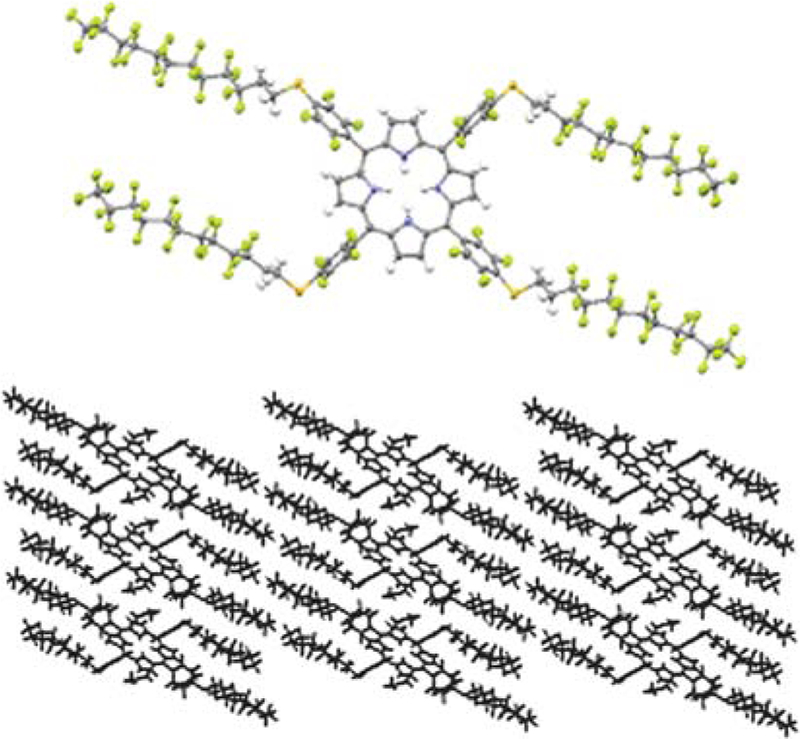
In addition to intermolecular interactions, solvent, concentration, evaporation rate, surface properties, and mode of deposition combine to dictate the morphology of self-organizing systems on surfaces.18,19 In this case the fluorous alkanes drive the formation of the thin films with C60, since similar films are not observed using an analogue with hydrocarbon chains and the same deposition conditions, vide infra. In order to assure the same amount of 1 is deposited in all the experiments, UV-visible spectra were recorded after each immersion. The Soret band of 1 on ITO is weakly red-shifted to 422 nm. The fluorescence of 1 is strongly quenched in the presence of C60 in the self-organized thin film on the substrate (Fig. 2). These data can be interpreted as photoinduced electron transfer from the porphyrin to the fullerene, as observed previously for por–C60 systems.10,11,20
Fig. 2.
Fluorescence spectra of film of 1 on ITO (red) and film of 1–C60 formed by dipping the ITO into a 1 : 1 solution once (green). Spectra are normalized to porphyrin absorption at the 422 nm excitation and baselines are corrected.
In order to characterize the morphology and the thickness of the films, AFM studies of the films on the substrates were conducted. As expected, AFM experiments reveal that the overall morphologies of the films of 1 alone and the film from dipping in the 1–C60 mixture are significantly different. The morphology of the material deposited on ITO (rms roughness of 0.5 nm) from immersion in a 6 × 10⁻⁵ M solution of 1 in CCl4 appears as irregular flat domains of different horizontal and vertical sizes. Similar immersions in C60 yield sporadic aggregates. Conversely, immersion in a solution containing both components results in thin films with a granular morphology. In order to determine the thickness of the 1–C60 film, a 4 μm2 well was shaved on the surface using a contact mode imaging tip and applying a force equal to 619 nN. The well was then imaged in tapping mode. Three nanoshaving experiments were conducted on each of five films prepared by the same methods, and the average thickness of the films was 7 ± 0.4 nm. Due to the asperities in the substrate and film surfaces (film rms roughness of ca. 1 nm), the averages of each were used, as calculated by the Veeco software.
A second dipping in the 1 : 1 solution yields ca. 12 nm thick films with analogous granular morphologies which is consistent with the ca. double absorbance of the Soret band. A second deposition of only 1 yields more complete films with similar flat topologies. Further dipping of either does not add any materials to the substrate (supporting information). †
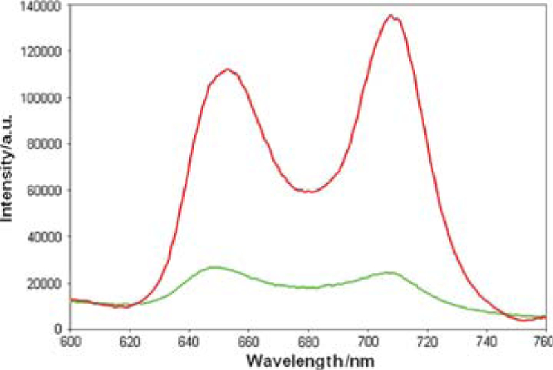
AFM in combination with laser scanning confocal microscopy was used to correlate film morphology to photonic activity of the material. For films of 1 only on ITO, the intensity of the fluorescence is in homogeneously distributed across the ITO surface. Areas with strong fluorescence have corresponding AFM images that show large flat domains, with an average lateral dimension of 1.5 μm, and smaller flat domains, with an average lateral dimension of 33 nm. There is a paucity of any material observed on the substrate when only C60 is in the dipping solution. In contrast, when the ITO is immersed in a 1 : 1 solution of 1–C60, a thin film is formed (Fig. 3), with characteristic features observed neither for 1 nor for C60 alone. The co-deposition of 1 and C60 results in films with a high coverage and granular texture on ITO surfaces. Consistent with the fluorescence spectra of the films (Fig. 2), the confocal fluorescence microscopy reveals that the porphyrin fluorescence is strongly quenched. Thus both the AFM and fluorescence experiments confirm that the C60 resides close to the porphyrin and that the two components do not separate into domains of each. This observation indicates that the interactions between TPPF100 and C60, which are expected to increase significantly as the solvent evaporates, dictate the morphology of the material deposited onto the ITO surface and the photophysical properties are consistent with other solid state porphyrin–C60 constructs.8
Fig. 3.
Combined laser scanning and atomic force microscopy characterization of films. Left: deposition of 1 on ITO results in an incomplete film with observable fluorescence (top left) and corresponding flat features (bottom left). Right: deposition from a 1 : 1 solution of 1 and C60 in CCl4 results in a high coverage film with no observable fluorescence (top right) and a granular topology (bottom right). Confocal data: all samples excited with a 488 nm laser. Five frames (317.2 × 317.2 µm, 60× objective) were collected and averaged in order to reduce background noise. AFM data: all samples were imaged with a Park 0.1 silicon nitride tip (k = 0.1 N m −1) in contact mode.
Larger AFM scans at multiple positions of the co-deposited film indicate the morphology persists over large areas. Samples stored in air and ambient light are stable for more than one month with no observed decomposition of the chromophores indicated by UV-visible spectroscopy. Considering the previous crystallographic data,9 one possible molecular arrangement is with C60 sandwiched between porphyrin molecules. Using the crystal data (fullerene diameter of 0.75 nm, and a porphyrin–C60 distance of 0.26 nm) a 7 nm thick film would have ca. seven layers. Alternatively the C60 could reside between the fluorous chains. Since sequential dipping of the substrate in separate solutions of 1 and C60 does not lead to films, there must be some intermolecular interactions and pre-organization in the evaporating solvent during deposition beyond π-stacking.
To understand the role of the fluorocarbon chains, the corresponding porphyrin bearing four hydrocarbon chains of the same length was synthesized (compound 2, see supporting information).† The same co-deposition experiments with 2 and C60 on ITO were conducted, and quite different results were found. Though UV-Vis data indicate the presence of some 2–C60 material on the surface, AFM experiments demonstrated that thin films are not formed, but only sporadic, amorphous aggregates. To compare the robustness of the two surface deposited films, the slides were sonicated in water and in 50 mM NaCl aqueous solution for 10 min. Remarkably, UV-Vis spectra show that only ca. 5% of the 1–C60 film is removed while nearly 70% of the 2–C60 film is lost and the presence of the fullerene is barely detectable. This indicates that the increased intermolecular interactions of the fluorocarbon moieties between the porphyrins and with C60 and the surface drive the self-organization of these films.
In conclusion we synthesized a new porphyrin bearing fluorous alkanes through a facile and efficient procedure. The properties of the fluoroalkane groups allow the porphyrin chromophore to self-organize with C60 via a co-deposition process into thin films. The films are characterized by significant quenching of the porphyrin fluorescence by electron transfer to the fullerene.21 The photoelectrochemical properties of this film will be the subject of further studies.
Supplementary Material
Acknowledgments
We thank Dr Joao Tome´ for assistance with NMR spectroscopy, Dr Clifford Soll for assistance with mass spectrometry, and Alan Hicklin of SIF at UC Davis for his aid in the combined confocal and AFM studies. This work was supported by NSF grants to CMD (CHE-0554703) and to GYL (UC Davis, NSF DMR 0421521). Hunter College science infrastructure is supported by the National Science Foundation, the National Institutes of Health, including the RCMI program (G12-RR-03037) and the City University of New York.
Footnotes
Electronic supplementary information (ESI) available: Experimental procedures, synthesis and structural characterization of 1, 2, and films. CCDC reference number 670308. For ESI and crystallographic data in CIF or other electronic format see DOI: 10.1039/b806795c
Notes and references
Crystallographic data for 1. C92H26F100N4S4·4C2H6O, M = 3447.72, T = 100 K, triclinic, Pī, a = 9.3570(19), b = 10.938(2), c = 30.832(6) Å, α = 87.69(3), β = 88.34(3), γ = 77.12(3)°, V = 3073.1(11) Å3, Z = 1, Dc = 1.863 4 g cm−3, μ = 0.284 mm−1, F(000) = 1698, crystal 0.20 × 0.20 × 0.08 mm3, Θmax = 27.56, ranges −12 ≤ h ≤ 12, −14 ≤ k ≤ 14, −39 ≤ l ≤ 38, Rint = 0.086, wR2 = 0.191, reflections collected = 12247, independent reflections = 6936, parameters = 973.
The electronic spectrum of 1 in CCl4 displays a Soret band (417 nm, ε = 246 000 M−1 cm−1) and four Q-bands (509 nm, ε = 16400 M−1 cm−1; 538 nm, ε = 1840 M−1 cm−1; 587 nm, ε = 4800 M−1 cm−1; 639 nm, ε = 229 M−1 cm−1)
References
- 1.Bonifazi D, Spillmann H, Kiebele A, de Wild M, Seiler P, Cheng F, Güntherodt H-J, Jung T and Diederich F, Angew. Chem., Int. Ed, 2004, 43, 4759–4763. [DOI] [PubMed] [Google Scholar]
- 2.Imahori H, Fujimoto A, Kang S, Hotta H, Yoshida K, Umeyama T, Matano Y, Isoda S, Isosomppi M, Tkachenko NV and Lemmetyinen H, Chem.–Eur. J, 2005, 11, 7265–7275. [DOI] [PubMed] [Google Scholar]
- 3.Imahori H, Yamada H, Ozawa S, Ushidab K and Sakata Y, Chem. Commun, 1999, 1165–1166. [Google Scholar]
- 4.Ikeda A, Hatano T, Shinkai S, Akiyama T and Yamada S, J. Am. Chem. Soc, 2001, 123, 4855–4856. [DOI] [PubMed] [Google Scholar]
- 5.Hasobe T, Imahori H, Kamat PV and Fukuzumi S, J. Am. Chem. Soc, 2003, 125, 14962–14963. [DOI] [PubMed] [Google Scholar]
- 6.Isosomppi M, Tkachenko NV, Efimov A, Kaunisto K, Hosomizu K, Imahorib H and Lemmetyinen H, J. Mater. Chem, 2005, 15, 4546–4554. [Google Scholar]
- 7.Umeyama T and Imahori H, Photosynth. Res, 2006, 87, 63–71. [DOI] [PubMed] [Google Scholar]
- 8.Boyd PDW and Reed CA, Acc. Chem. Res, 2005, 38, 235–242. [DOI] [PubMed] [Google Scholar]
- 9.Hosseini A, Hodgson MC, Tham FS, Reed CA and Boyd PDW, Cryst. Growth Des, 2006, 6, 397–403. [Google Scholar]
- 10.Hosseini A, Taylor S, Accorsi G, Armaroli N, Reed CA and Boyd PDW, J. Am. Chem. Soc, 2006, 128, 15903–15913. [DOI] [PubMed] [Google Scholar]
- 11.Guldi DM, Chem. Commun, 2000, 321–327. [Google Scholar]
- 12.Guldi DM, Chem. Soc. Rev, 2001, 31, 22–36. [DOI] [PubMed] [Google Scholar]
- 13.Liu C.-y., Pan H.-l., Fox MA and Bard AJ, Chem. Mater, 1997, 9, 1422–1429. [Google Scholar]
- 14.Kirsch P, Modern Fluoroorganic Chemistry: Synthesis, Reactivity, Applications, Wiley, 2004. [Google Scholar]
- 15.Milic TN, Chi N, Yablon DG, Flynn GW, Batteas JD and Drain CM, Angew. Chem, 2002, 41, 2117–2119. [PubMed] [Google Scholar]
- 16.Boyd PDW, Hodgson MC, Rickard CEF, Oliver AG, Chaker L, Brothers PJ, Bolskar RD, Tham FS and Reed CA, J. Am. Chem. Soc, 1999, 121, 10487–10495. [Google Scholar]
- 17.Sawamura S and Fujita N, Carbon, 2007, 45, 965–970. [Google Scholar]
- 18.Drain CM and Chen X, in Encyclopedia of Nanoscience & Nanotechnology, ed. Nalwa HS, American Scientific Press, New York, 2004, pp. 593–616. [Google Scholar]
- 19.Drain CM, Smeareanu G, Batteas J and Patel S, in Dekker Encyclopedia of Nanoscience and Nanotechnology, ed. Schwartz JA, Contescu CI and Putyera K, Marcel Dekker, Inc., New York, 2004, pp. 3481–3502. [Google Scholar]
- 20.Wessendorf F, Gnichwitz JF, Sarova GH, Hager K, Hartnagel U, Guldi DM and Hirsch A, J. Am. Chem. Soc, 2007, 129, 16057–16071. [DOI] [PubMed] [Google Scholar]
- 21.Oswald F, Islam D-MS, Araki Y, Troiani V, Caballero R, de la Cruz P, Ito O and Langa F, Chem. Commun, 2007, 4498–4500. [DOI] [PubMed] [Google Scholar]
Associated Data
This section collects any data citations, data availability statements, or supplementary materials included in this article.