Abstract
This paper reports on a chip cooling solution using polydimethylsiloxane (PDMS) based microfluidic devices filled with n-Octadecane. A thick SU-8 layer of 150 µm is used as the master mold for patterning PDMS fabrication. With the SU-8 mold, patterns with straight lines at microscale have been fabricated with standard micro-electro-mechanical system (MEMS) technology. Thermal polymer bonding technique is used to bond the PDMS pattern directly to a flat polydimethylsiloxane (PDMS) film which results in the sealed microchannels. n-Octadecane as a phase-change material has been successfully filled in the microchannels using a dispensing machine. Infrared thermal image shows a sharp contrast of the temperature distribution between the chip with n-Octadecane and the empty chip during the same heating process. This result indicates an efficient cooling performance of the microchannel device with phase-change material. A thermal stimulation test demonstrates that a 16 °C-lower temperature difference can be achieved. This microchannel device, benefited from the flexibility of PDMS substrate, shows specific advantages in meeting the need for the heat dissipation of flexible electronics such as flexible displays, electronic skins, and wearable electronics. Latent heat of the phase-change material can keep the temperature of devices relatively lower over a period of time, which shows potential application values on discontinuously active flexible electronic devices.
Keywords: MEMS, polymer, micro-channel device, phase-change material, chip cooling, thermal management, flexible electronics
1. Introduction
As more and more components are integrated per unit area, electronic devices are having more complicated functions with better performance. On the other hand, unfortunately, a more severe problem of heat dissipation has become the “hot” topic of microelectronics [1,2,3,4], which also relates to high power consumption per unit area. The overall reliability and lifetime of laptops, smart phones, and lithium batteries have been threatened by the elevated temperature from over-heating. A proper cooling solution is necessary to solve the thermal management challenge for “More than Moore” semiconductor devices.
New materials with superior thermal conductivity, such as carbon nanotubes, have recently been used to enhance the heat dissipation [5,6,7]. Other materials such as phase-change materials (PCMs) have also been used since they can store or release large quantities of latent heat within a narrow temperature interval during phase change, which have shown great potential in the fields of energy storage and thermal regulation [8,9,10,11].
Micro-channel structures have also been widely researched to cool down the microelectronic chip either with air or filling with super-moist fluids [12,13,14,15]. Youngcheol Joo et al. fabricated metal microchannels through a single-mask process and achieved an economical chip cooling solution with air as the coolant [12]. Kailun Zhang et al. fabricated microchannels filled with super-moist fluids and nanofluids to form a thermosyphon boiling system [14]. In these works, the fabrication of microchannels becomes a crucial part for chip cooling. Different from a traditional heat sink with static fins, Yi, P. et al. proposed dynamic nanofin heat sinks magnetically controlling CrO2 nanoparticles onto hot spots, which significantly increased the heat sinking efficiency [16].
Droplet-based cooling technologies also provided novel strategies for chip cooling. Electrowetting phenomenon was adapted in chip cooling by moving the droplet along the substrate [17]. Electrical induced oscillation by periodic direct current (DC) pulse or optimized alternating current (AC) pulse of micro-liter sized droplet enhanced with nanoparticles also shows a potential application in hot-spot cooling [18,19].
In recent years, flexible electronics appeared in people’s vision and were regarded as a promising technology that may have a revolutionary influence on the future of electronic devices. However, research about a cooling solution aiming at flexible electronics is still not sufficient. Cooling systems designed for chips or other solid electronic devices are usually rigid and not suitable to be applied to flexible devices. Pola T. tested flexible heat sink substrates to achieve a better heat dissipation performance for wearable devices and found that the heat conduction depended on the amount of metal in the tested material [20]. However, the design could not keep a constant temperature. Oshman C. proposed a flat flexible polymer heat pipes that were a highly flexible thermal management solution [21], while the size was not small enough to be applied on fine flexible electronics, such as electronic skins, and wearable electronics.
PDMS, as a well-studied micro-electro-mechanical system (MEMS) material, can be perfectly integrated with flexible electronic devices because of its flexibility and elasticity. The application of PDMS to embedded electronic components required an improvement in heat exchange. Incorporating synthetic micro-diamond can change the physicochemical properties and enhance the thermal conductivity of PDMS [22]. It has been proven that 10% w/w Al2O3 nanoparticles in PDMS can significantly increase the thermal conductivity [23]. In this study, we have developed a chip cooling solution using PDMS microchannels filled with PCM. PCMs can absorb or release large amounts of latent heat from the ambient environment through changes in state or structure within a quite narrow temperature scope [24], and have shown great potentials in waste heat utilization [25], energy-storing building [26,27], solar energy storage systems [28], thermal comfort textiles [29], and heat management of electric devices [30,31], etc. Various PCMs, including organic, inorganic, and eutectic ones [32] have been adopted as the latent heat-type functional material, among which, n-Octadecane, one of the organic PCMs, was utilized most widely due to its high heat storage density, mild phase-change temperature, and good chemical stability. However, there are some obstacles such as leakage of melted n-Octadecane, and volume change during the phase change, which limits its practical use for micro scale devices. To overcome these problems, it was generally microencapsulated with either inorganic materials [10,33] or organic polymers [34,35,36]. In this paper, we reported, for the first time, a novel technique of encapsulating PCMs into MEMS device with parallel straight-lines microchannels for chip cooling application.
As shown in Figure 1, PDMS based microchannel device can be fabricated with MEMS processes which are compatible with standard integrated circuits (IC) technology. This design takes the advantages of both the PCM and the microchannel structure, which could help to cool down the over-heated microelectronic chip efficiently. Through a heating test for a prototype device, the PDMS-based microchannel device with PCM can lower the temperature of devices over a period of time, which is efficient for device cooling. Furthermore, this patch-like cooling device is flexible and compact in size, which makes it simple and accessible enough to be combined with flexible electronics. In this way, it is outstanding among other cooling solutions which were generally rigid or too large to apply in flexible electronics. The flexible PDMS-based microchannel device with PCM has demonstrated a promising application for future flexible electronics.
Figure 1.
A schematic diagram of the polydimethylsiloxane (PDMS) based microfluidic device filled with phase-change material for chip cooling in integrated circuits.
2. Materials and Methods
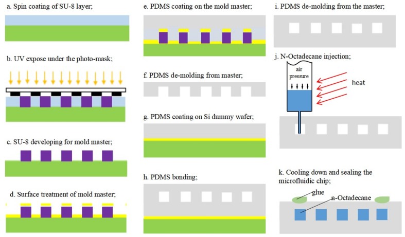
Figure 2 shows the process flow of the microchannel chip with the n-Octadecane phase-change material. The fabrication details are introduced as follow.
Figure 2.
The fabrication process for the microfluidic device, including the master mold fabrication (a–d); PDMS microchannels (e–i); and the injection of phase-change material (j,k).
2.1. Fabrication of the Mold Master
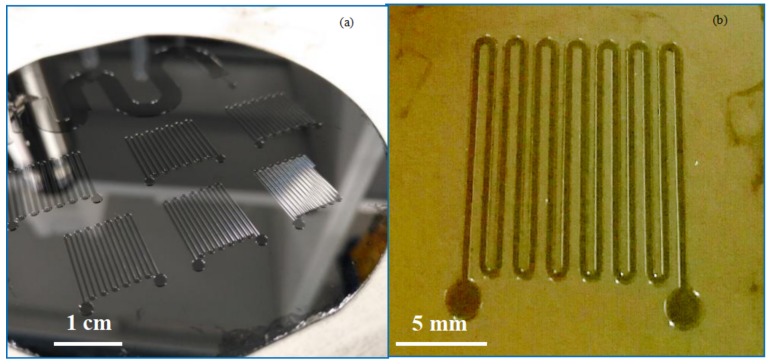
PDMS is a popular material used in the fabrication of microfluidic chips based on injection molding technology. SU-8 is a commonly used epoxy-based negative photoresist, which has been proved as a good mold material for PDMS pattern. The thickness of the SU-8 could be tuned by the spin-rate during coating, and the structure with micro scale dimension could be easily fabricated with optical lithography. Therefore, high aspect ratio up to 20:1 can be achieved for SU-8, which makes it suitable as master mold to fabricate the micro channels [37,38]. A novel modification of conventional microfabrication steps to fabricate large-area, high-aspect-ratio SU-8 molds for PDMS microfluidic devices were shown by Natarajan S. et al. [39]. In 2014, Aaron J Dy et al. introduced two approaches to master mold fabrication using SU-8, which can be applied to many lab-on-a-chip functions [40]. In our study, a thick layer photoresist (SU-8 1075, Gersteltec Sàrl, Pully, Switzerland) was used to obtain a master mold with designed channel geometry of 2-D pattern and a specific depth. On a 4-inch silicon wafer, we first spin-coated the SU-8 1075 resist at 1200 rpm, which gave a layer thickness of 150 µm measured by a step profiler (Dektak-XT-A, Bruker Corporation, Billerica, MA, USA). A standard soft bake was followed at 120 °C for 5 min (Figure 2a). With a photo-mask, the SU-8 layer was exposed to ultraviolet (UV) light (Figure 2b) and developed in propylene glycol monomethyl ether acetate (PGMEA) after a post-bake at 95 °C (Figure 2c). To avoid adhesion problems during the following PDMS de-molding process, the SU-8 master mold was treated with a release agent (release M 4030 from D&D Chemical, Shanghai, China) (Figure 2d). Figure 3 shows the microscopic pictures of the completed mold master with straight line geometry.
Figure 3.
The fabricated SU-8 master mold for the following PDMS casting. (a) a few molds on a 4-inch silicon wafer; (b) close-up view of one mold for channels with straight lines.
2.2. Fabrication of PDMS Microchannels
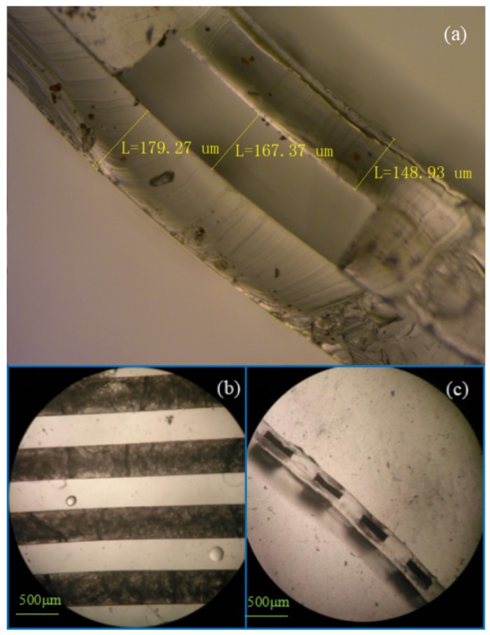
PDMS was prepared by mixing the prepolymer and curing agent at a weight ratio of 10:1 (Dow Corning SYLGARD184, Midland, MI, USA). The mixture was degassed in a vacuum chamber to remove the air bubbles. Then, the PDMS was poured onto the SU-8 master mold and spin-coated at 400 rpm for 30 s, which gave a layer thickness of about 320 µm measured in the microscopic photo of the cross-section as shown in Figure 8 in the following pages (Figure 2e). After a thermal curing process at 70 °C for 2 h, the PDMS film was peeled off the SU-8 mold as shown in Figure 2f. On another silicon dummy wafer, PDMS film was spin-coated at 500 rpm for 30 s after surface treatment with the release agent mentioned above. As shown in Figure 2g, this process gives a flat PDMS film with a thickness of about 180 µm measured from the cross-section in Figure 8. The PDMS film with patterns will be bonded to the flat PDMS film (Figure 2h).
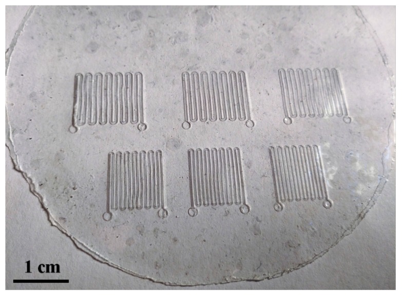
Afterward, a thermal bonding technique was performed using a custom-made setup at 120 °C for 12 h with a contact pressure of 3.4 kPa. It has been reported previously that uncured PDMS adhesive bonding would result in better bonding strength for PDMS-PDMS bonding than treated by O2 plasma or corona discharge [41], although O2 plasma treatment could enhance the bonding strength for PDMS-glass bonding [42,43]. Therefore, no surface treatment was applied in our experiment for the PDMS-PDMS adhesive bonding. The bonded films were peeled off from the silicon dummy wafer after the thermal bonding (Figure 2i). Figure 4 shows the microchannel chips in 4-inch wafer scale.
Figure 4.
Overall, six microfluidic chips are fabricated simultaneously with PDMS-PDMS bonded film.
2.3. Injection with Phase-Change Material
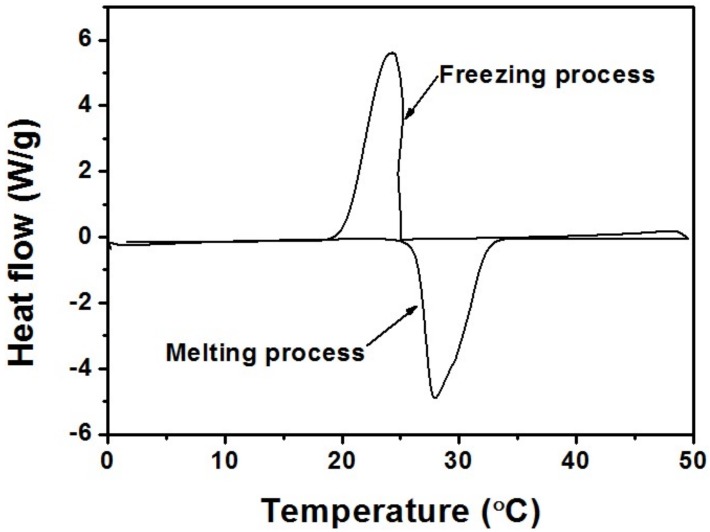
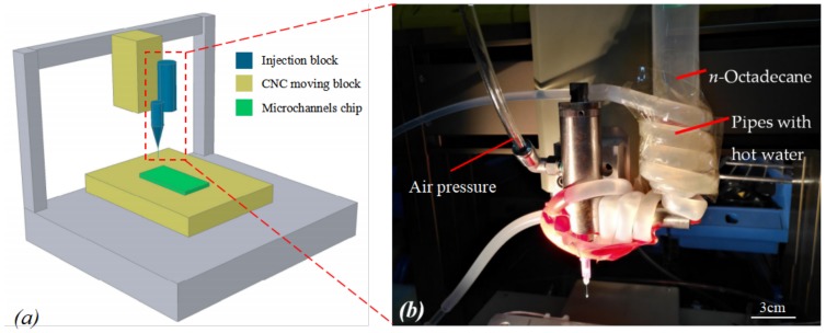
n-Octadecane (CH3(CH2)16CH3, AR, 98%, purchased from Aladdin, Georgetown, TX, USA) with the density of 0.78 g/cm3, thermal conductivity of 0.151 W/m·K and heat capacity of 2.16 J/g·K, is a classification of phase-change material with high melting enthalpy and mild phase-change temperature. When melted, it can be injected into the microchannels. Thermal properties of n-Octadecane were determined using a Q200 differential scanning calorimeter (DSC) (TA Instruments, New Castle, DE, USA) at a temperature range from 0 to 50 °C at the heating/cooling rate of 5 °C/min. From the DSC curve presented in Figure 5, the phase-change temperature ranges of n-Octadecane are approximately 24.0–34.1 °C for the melting process and 18.1–25.1 °C for the solidification process. The peak melting temperature and latent heat are measured to be 27.9 °C and 216.6 J/g for the fusion process and 24.3 °C and 215.8 J/g for the crystallization process, respectively. As shown in Figure 6a, a dispensing machine was used in order to precisely control the injection position for this specific micro-scale channel. To melt the n-Octadecane material, we have twisted a pipe of soft rubber with hot water flowing around the container for n-Octadecane, which would keep the temperature of the container higher than the melting point of n-Octadecane, as shown in Figure 6b. Meanwhile, the pinhead of the injection system was heated by a lamp to avoid any block from the solidification of n-Octadecane. A piezoelectric stage was used to control the position of the needle precisely injecting to the middle of the two PDMS films at the inlet of the microfluidic chip. Then an air pressure was applied to the container to push the liquid-phased n-Octadecane into the microchannels (Figure 2j). A hole was poked at the outlet end of the microfluidic chip so that the air could be released when the liquid was injected into the channel.
Figure 5.
The differential scanning calorimeter (DSC) curve of n-Octadecane.
Figure 6.
(a) The schematic diagram of phase-change material (PCM) injection system using a dispensing machine; (b) Close-up view of the injection needle and the container for PCM.
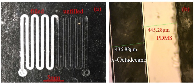
Figure 7a shows a microchannel which has been partly filled with the PCM. A better demonstration can be seen with the videos in the Supplementary Materials, where carbon-ink was manually injected into a microchannel and PCM was injected into another microchannel using the dispensing machine, respectively. When the PDMS microchannel was filled with the liquid n-Octadecane, the injection needle was quickly lifted by the stage controller. Finally, the microfluidic chip filled with n-Octadecane was quickly cooled down on an ice pack so that the n-Octadecane could solidify in the channel. The inlet and outlet openings were then sealed as shown in Figure 2k. Figure 7b shows the microscopic image of the solidified n-Octadecane (dark part) in the transparent PDMS chip.
Figure 7.
(a) The microchannel is partly filled with n-Octadecane which could solidify at room temperature; (b) the n-Octadecane turns to dark under microscopy due to the disorder of crystal grains.
Figure 8 provides more fabrication details of the device. A cross-sectional view of the microfluidic channel is shown in Figure 8a, where the two PDMS layers are well bonded together. Figure 8b shows the top view of the filled chip while the cross-section is shown in Figure 8c. The n-Octadecane material appears dark under the microscope due to the disorder of the crystal grains after solidification.
Figure 8.
The PDMS-PDMS microchannels (a) before PCM filling; (b,c) after PCM filling.
3. Results and Evaluation of the Cooling Performance
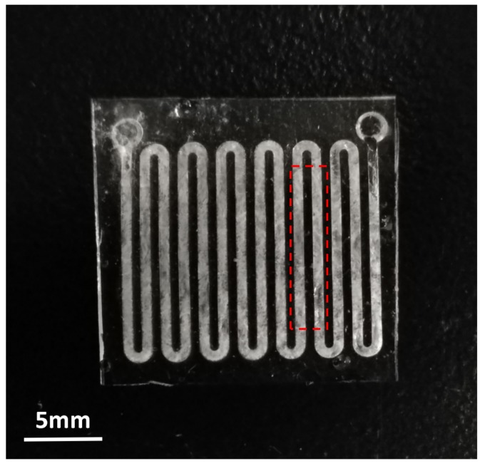
The energy-storage behaviors of n-Octadecane and PDMS microchannels with or without PCM were analyzed using a TA Q200 differential scanning calorimeter (DSC) within the temperature range of 0 to 50 °C at a heating/cooling rate of 5 °C/min under the protection of nitrogen. A sample piece of about 8 mg (the instrument cannot take too much or too little sample for accurate measurement) was cut off from the PDMS microchannels device filled with n-Octadecane, which is applicable for the DSC instrument. The sample with a rectangular shape of 11.1 mm × 2.5 mm, including two parallel micro-channels, was tailored for testing as shown in Figure 9.
Figure 9.
A PDMS-based microchannels device filled with n-Octadecane where the wireframe shows the area being cut off for DSC testing.
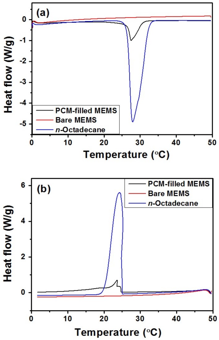
Figure 10 shows the DSC curves of n-Octadecane and the MEMS cooling device with and without PCM, using the same test parameters as mentioned above. The bare MEMS channel has no endo-/exo-thermic peaks, which means that the thermal effects of the composite MEMS are only attributed to the incorporation of the n-Octadecane. During the heating/cooling process, the n-Octadecane encapsulated within PDMS microchannels shows a slight delay in both crystallization and melting were observed, because of the low thermal conductivity of PDMS. The stored or released latent heats of the MEMS filled with PCM reach to 34.74 J/g and 38.11 J/g, indicating good ability for thermal energy storage or temperature regulation.
Figure 10.
DSC curves of n-Octadecane, bare MEMS, and the n-Octadecane-filled MEMS during the (a) melting and (b) freezing process.
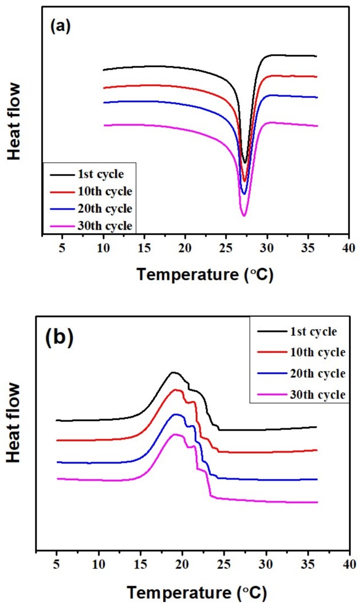
Figure 11 shows the DSC curves of PCM-filled MEMS after 1, 10, 20, and 30 heating/cooling cycles. The PCM-filled MEMS from the first cycle to the 10th, 20th, and 30th cycles shows good coincident melting and freezing peaks, which means the melting and crystallizing temperatures are very close and there is almost no change of the latent heats in the PCM-filled MEMS after experiencing 30 heating/cooling cycles. The PCM-filled MEMS has demonstrated a good thermal cycling reliability.
Figure 11.
DSC thermograms of PCM-filled MEMS after undergoing 1, 10, 20, and 30 heating/cooling cycles during the (a) melting and (b) freezing process.
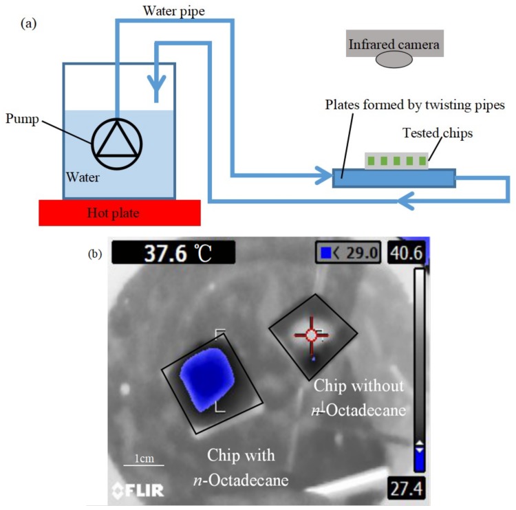
To characterize the chip cooling performance of our device, we have designed a test setup with a hot water circulation system to control the substrate temperature and an infrared (IR) camera (FLUKE Ti110, Everett, WA, USA) to measure the chip temperature distribution, as shown in Figure 12a. For comparison, two pieces of devices in the same size with the same structure were tested, one of which was filled with n-Octadecane while the other one was empty. The two devices were put on a silicon substrate wafer which was gradually heated up by the hot water circulation system.
Figure 12.
(a) A schematic diagram of the test system with a hot water circulation system to control the substrate temperature and an infrared camera (FLUKE Ti110) to measure the chip temperature distribution; (b) The comparison between a device filled with n-Octadecane and an empty device (the blue zone shows temperature of 27.4 °C for the device with n-Octadecane).
When the temperature of the substrate was increased from room temperature (27 °C) to 40 °C, the infrared thermal image of the two devices were taken, as shown in Figure 12b. From the image, we can see that the microchannel of with n-Octadecane has significant cooling effect on the device as the temperature of the device is kept at 27.4 °C; while without n-Octadecane, the temperature of the other device is increased up to 40 °C together with the substrate. This demonstration proves that the PDMS-PDMS microchannel filled with n-Octadecane can be useful for the chip cooling application.
It should be noted that the microfluidic device should have higher thermal absorption capability when the volume ratio of n-Octadecane to the whole device increases. Therefore, decreasing the thickness of the PDMS is an approach for better thermal management performance. A more detailed study of the geometry effect on the cooling efficiency is undertaken and will be shown soon.
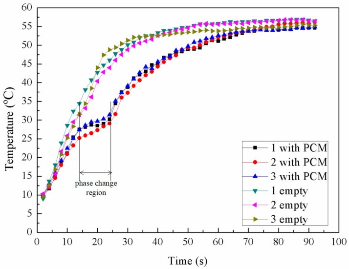
To study the cooling effect quantitatively, a water bath heating system was set up. Three chips filled with PCM and three empty chips were examined by heating process separately. They were attached to rectangular silicon pieces of the same size which were heated up simultaneously. These chips were heated from 10 °C by a heat source of constant 65 °C when the room temperature was 24.5 °C. During the heating process, the chips can continuously absorb heat from the source until a final thermal equilibrium was achieved. Figure 13 shows the curves of the temperature variation over time. Either with or without PCM, the three chips for each type exhibit the same trend for the measured curve, which proves excellent repeatability of the devices during the test. For empty chips, the smooth curves show a continuous increase in the temperature which saturated at approximately 55 °C when reaching the equilibrium. On the other hand, a comparatively flat stage was observed for the chips with PCM, which indicates that PCM in the microchannel undergoes a phase change period and a large amount of heat is absorbed with little temperature increase. The large gap between the temperature curves of the two types of devices has clearly demonstrated the cooling effect of PCM. This phase change period plays an important role in the cooling performance.
Figure 13.
The temperature variation of the three empty chips and three chips with PCM over time.
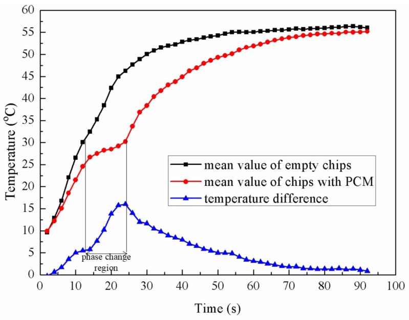
In order to take a deeper investigation on the temperature changing over time especially the phase change period, Figure 14 shows the mean value of three empty chips and three chips filled with n-Octadecane, respectively. From the figure, there is a relatively flat section of the curve around 26–30 °C for the chips with PCM. During this period, the temperature difference between two types of chips increases rapidly, reaching the maximum value of 16 °C at the end of phase change period when the mean temperature of the chips with PCM is 29 °C while the chips without PCM is about 46 °C. If we define a ratio η as the temperature difference between the two chips divided by the mean temperature of the chip without PCM, this ratio of η goes up to 35.1% at this point, which shows an efficient cooling effect. Before and after the phase changing region, the mean temperature of chips with PCM is cooled to 25 °C and 35 °C, with η of 18.3% and 25.1%, respectively, which also demonstrates a good function of this cooling strategy. Both empty chips and chips filled with PCM reached a same equilibrium temperature in the end according to the same constant thermal source.
Figure 14.
Mean value of the temperature of three empty chips, mean value of the temperature of three chips with PCM, and the temperature difference during the heating test.
4. Conclusions
In this paper, we have fabricated PDMS based microfluidic chips filled with phase-change material for chip cooling applications. The SU-8 photoresist is used as the master mold for PDMS patterning, and PDMS-PDMS adhesive bonding is applied to achieve sealed channel structure with various patterns at microscale using standard MEMS technology. The channel is filled with n-Octadecane as a phase change material which can absorb heat efficiently, which prevents or slows down the temperature rising from the heating source. A prototype device shows that the microfluidic chip with n-Octadecane can be kept at room temperature while the other chip without n-Octadecane is heated up to 40 °C during the same period. The curves of the variation of temperature over time show a clear thermal property that the temperature can be kept constantly to some extent. A temperature reduction around 16 °C can be achieved at the end of the phase change period of n-Octadecane. Furthermore, heating and cooling experiments with different PDMS microchannel devices demonstrate the repeatability of the method and the durability of the PCM. Different from other stiff microfluidic cooling devices designed for macro devices, the flexible PDMS sheet and miniaturized microchannels with PCM make it compatible with the plastic substrates of flexible electronics. This chip cooling solution takes the advantages of both microchannels cooling and phase-change material, which shows a promising application in solving the thermal management issue for future flexible electronics.
Acknowledgments
This work is supported by National Natural Science Foundation of China (Project No. 51505209) and Shenzhen Science and Technology Innovation Committee (Projects Nos. JCYJ20170412154426330 and KQTD2015071710313656). Fei Wang is also supported by Guangdong Special Support Program (Project No. 2015TQ01X555) and Guangdong Natural Science Funds (Project Nos. 2015A030313812 and 2016A030306042). Dazhu Chen is supported by Guangdong Natural Science Funds (Project Nos. 2014A030313561).
Supplementary Materials
The following are available online at http://www.mdpi.com/2072-666X/9/4/165/s1, Video S1: Ink.avi; Video S2: pcm.avi; Video S3: heating.avi.
Author Contributions
Fei Wang and Dazhu Chen conceived and designed the experiments; Zong Liu and Xingwei Chen performed the experiments; Zong Liu, Xingwei Chen, and Fei Wang analyzed the data; Siyin Qin, Xingwei Chen, Dazhu Chen, and Fei Wang contributed reagents/materials/analysis tools; all the authors wrote the paper together.
Conflicts of Interest
The authors declare no conflict of interest.
References
- 1.Ollier E., Soupremanien U., Remondière V., Dijon J., Le Poche H., Seiler A., Lefevre F., Lips S., Kinkelin C., Rolland N., et al. Thermal management of electronic devices by composite materials integrated in silicon. Microelectron. Eng. 2014;127:28–33. doi: 10.1016/j.mee.2014.03.016. [DOI] [Google Scholar]
- 2.Tu J., Yuen W., Gong Y. An assessment of direct chip cooling enhancement using pin fins. Heat Transf. Eng. 2012;33:845–852. doi: 10.1080/01457632.2012.654445. [DOI] [Google Scholar]
- 3.Chowdhury I., Prasher R., Lofgreen K., Chrysler G., Narasimhan S., Mahajan R., Koester D., Alley R., Venkatasubramanian R. On-chip cooling by superlattice-based thin-film thermoelectrics. Nat. Nanotechnol. 2009;4:235–238. doi: 10.1038/nnano.2008.417. [DOI] [PubMed] [Google Scholar]
- 4.Kercher D., Jeong-Bong L., Brand O., Allen M., Glezer A. Microjet cooling devices for thermal management of electronics. IEEE Trans. Compon. Packag. Technol. 2003;26:359–366. doi: 10.1109/TCAPT.2003.815116. [DOI] [Google Scholar]
- 5.Kordás K., Tóth G., Moilanen P., Kumpumäki M., Vähäkangas J., Uusimäki A., Vajtai R., Ajayan P. Chip cooling with integrated carbon nanotube microfin architectures. Appl. Phys. Lett. 2007;90:123105. doi: 10.1063/1.2714281. [DOI] [Google Scholar]
- 6.Fu Y., Nabiollahi N., Wang T., Wang S., Hu Z., Carlberg B., Zhang Y., Wang X., Liu J. A complete carbon-nanotube-based on-chip cooling solution with very high heat dissipation capacity. Nanotechnology. 2012;23:045304. doi: 10.1088/0957-4484/23/4/045304. [DOI] [PubMed] [Google Scholar]
- 7.Huang Z., Pan T., Gao M., Lin Y. Chip Cooling with Carbon Nanotube Heat Sink; Proceedings of the International Conference on Electronic Packaging Technology; Chengdu, China. 12–15 August 2014; pp. 183–185. [Google Scholar]
- 8.Kandasamy R., Wang X., Mujumdar A. Transient cooling of electronics using phase change material (PCM)-based heat sinks. Appl. Therm. Eng. 2008;28:1047–1057. doi: 10.1016/j.applthermaleng.2007.06.010. [DOI] [Google Scholar]
- 9.Pielichowska K., Pielichowski K. Phase change materials for thermal energy storage. Prog. Mater. Sci. 2014;65:67–123. doi: 10.1016/j.pmatsci.2014.03.005. [DOI] [Google Scholar]
- 10.Yu S., Wang X., Wu D. Microencapsulation of n-octadecane phase change material with calcium carbonate shell for enhancement of thermal conductivity and serving durability: Synthesis, microstructure, and performance evaluation. Appl. Energy. 2014;114:632–643. doi: 10.1016/j.apenergy.2013.10.029. [DOI] [Google Scholar]
- 11.Fan S., Gao H., Xu Q., Tan L. Nanoencapsulation of n-Octadecane Phase Change Material with Polyaniline Shell for Thermal Energy Storage; Proceedings of the 3rd International Conference on Advances in Energy and Environmental Science 2015; Zhuhai, China. 25–26 July 2015; pp. 1547–1550. [Google Scholar]
- 12.Joo Y., Yeh H., Dieu K., Kim C. Air cooling of a microelectronic chip with diverging metal microchannels monolithically processed using a single mask. J. Micromech. Microeng. 2008;18:115022. doi: 10.1088/0960-1317/18/11/115022. [DOI] [Google Scholar]
- 13.Colgan E., Furman B., Gaynes M., LaBianca N., Magerlein J., Polastre R., Bezama R., Marston K., Schmidt R. High performance and subambient silicon microchannel cooling. J. Heat Transf. 2007;129:1046. doi: 10.1115/1.2724850. [DOI] [Google Scholar]
- 14.Zhang K., Liu Z., Zheng B. A new 3D chip cooling technology using micro-channels thermosyphon with super-moist fluids and nanofluids. Energy Convers. Manag. 2016;128:44–56. doi: 10.1016/j.enconman.2016.09.065. [DOI] [Google Scholar]
- 15.Tullius J., Vajtai R., Bayazitoglu Y. A review of cooling in microchannels. Heat Transf. Eng. 2011;32:527–541. doi: 10.1080/01457632.2010.506390. [DOI] [Google Scholar]
- 16.Yi P., Khoshmanesh K., Chrimes A., Campbell J., Ghorbani K., Nahavandi S., Rosengarten G., Kalantar-zadeh K. Dynamic nanofin heat sinks. Adv. Energy Mater. 2014;4:1300537. doi: 10.1002/aenm.201300537. [DOI] [Google Scholar]
- 17.Paik P., Pamula V., Chakrabarty K. Adaptive cooling of integrated circuits using digital microfluidics. IEEE Trans. Very Large Scale Integr. (VLSI) Syst. 2008;16:432–443. doi: 10.1109/TVLSI.2007.915434. [DOI] [Google Scholar]
- 18.Chakraborty M., Ghosh A., DasGupta S. Enhanced microcooling by electrically induced droplet oscillation. RSC Adv. 2014;4:1074–1082. doi: 10.1039/C3RA46401F. [DOI] [Google Scholar]
- 19.Chakraborty M., Anand R., Rao P., Sen S., DasGupta S. Oscillating nanofluid droplet for micro-cooling. Sens. Actuators B Chem. 2017;239:562–570. doi: 10.1016/j.snb.2016.06.145. [DOI] [Google Scholar]
- 20.Pola T., Häkkinen T., Hännikäinen J., Vanhala J. Thermal performance analysis of 13 heat sink materials suitable for wearable electronics applications. Sci. Technol. 2013;3:67–73. [Google Scholar]
- 21.Oshman C., Li Q., Liew L., Yang R., Bright V., Lee Y. Flat flexible polymer heat pipes. J. Micromech. Microeng. 2012;23:015001. doi: 10.1088/0960-1317/23/1/015001. [DOI] [Google Scholar]
- 22.Waheed S., Cabot J., Macdonald N., Kalsoom U., Farajikhah S., Innis P., Nesterenko P., Lewis T., Breadmore M., Paull B. Enhanced physicochemical properties of polydimethylsiloxane based microfluidic devices and thin films by incorporating synthetic micro-diamond. Sci. Rep. 2017;7:15109. doi: 10.1038/s41598-017-15408-3. [DOI] [PMC free article] [PubMed] [Google Scholar]
- 23.Yi P., Awang R., Rowe W., Kalantar-zadeh K., Khoshmanesh K. PDMS nanocomposites for heat transfer enhancement in microfluidic platforms. Lab Chip. 2014;14:3419–3426. doi: 10.1039/C4LC00615A. [DOI] [PubMed] [Google Scholar]
- 24.Lin Y., Jia Y., Alva G., Fang G. Review on thermal conductivity enhancement, thermal properties and applications of phase change materials in thermal energy storage. Renew. Sustain. Energy Rev. 2018;82:2730–2742. doi: 10.1016/j.rser.2017.10.002. [DOI] [Google Scholar]
- 25.Makuta T., Kadoya K., Izumi H., Miyatake M. Synthesis of cyanoacrylate-covered xylitol microcapsules for thermal storage. Chem. Eng. J. 2015;273:192–196. [Google Scholar]
- 26.Tyagi V., Kaushik S., Tyagi S., Akiyama T. Development of phase change materials based microencapsulated technology for buildings: A review. Renew. Sustain. Energy Rev. 2011;15:1373–1391. doi: 10.1016/j.rser.2010.10.006. [DOI] [Google Scholar]
- 27.Zhang H., Xing F., Cui H., Chen D., Ouyang X., Xu S., Wang J., Huang Y., Zuo J., Tang J. A novel phase-change cement composite for thermal energy storage: Fabrication, thermal and mechanical properties. Appl. Energy. 2016;170:130–139. doi: 10.1016/j.apenergy.2016.02.091. [DOI] [Google Scholar]
- 28.Ma G., Liu S., Xie S., Jing Y., Zhang Q., Sun J., Jia Y. Binary eutectic mixtures of stearic acid-n-Butyramide/n-Octanamide as phase change materials for low temperature solar heat storage. Appl. Therm. Eng. 2017;111:1052–1059. doi: 10.1016/j.applthermaleng.2016.10.004. [DOI] [Google Scholar]
- 29.Mondal S. Phase change materials for smart textiles—An overview. Appl. Therm. Eng. 2008;28:1536–1550. doi: 10.1016/j.applthermaleng.2007.08.009. [DOI] [Google Scholar]
- 30.Al-Hallaj S., Selman J. Thermal modeling of secondary lithium batteries for electric vehicle/hybrid electric vehicle applications. J. Power Sources. 2002;110:341–348. doi: 10.1016/S0378-7753(02)00196-9. [DOI] [Google Scholar]
- 31.Saha S., Dutta P. Thermal management of electronics using PCM-based heat sink subjected to cyclic heat load. IEEE Trans. Compon. Packag. Manuf. Technol. 2012;2:464–473. doi: 10.1109/TCPMT.2011.2180021. [DOI] [Google Scholar]
- 32.Sharma A., Tyagi V., Chen C., Buddhi D. Review on thermal energy storage with phase change materials and applications. Renew. Sustain. Energy Rev. 2009;13:318–345. doi: 10.1016/j.rser.2007.10.005. [DOI] [Google Scholar]
- 33.Zhang H., Wang X., Wu D. Silica encapsulation of n-Octadecane via sol–gel process: A novel microencapsulated phase-change material with enhanced thermal conductivity and performance. J. Colloid Interface Sci. 2010;343:246–255. doi: 10.1016/j.jcis.2009.11.036. [DOI] [PubMed] [Google Scholar]
- 34.Zhang H., Wang X. Synthesis and properties of microencapsulated n-Octadecane with polyurea shells containing different soft segments for heat energy storage and thermal regulation. Sol. Energy Mater. Sol. Cells. 2009;93:1366–1376. doi: 10.1016/j.solmat.2009.02.021. [DOI] [Google Scholar]
- 35.Qiu X., Li W., Song G., Chu X., Tang G. Fabrication and characterization of microencapsulated n-Octadecane with different crosslinked methylmethacrylate-based polymer shells. Sol. Energy Mater. Sol. Cells. 2012;98:283–293. doi: 10.1016/j.solmat.2011.11.018. [DOI] [Google Scholar]
- 36.You M., Wang X., Zhang X., Zhang L., Wang J. Microencapsulated n-Octadecane with styrene-divinybenzene co-polymer shells. J. Polym. Res. 2010;18:49–58. doi: 10.1007/s10965-010-9390-8. [DOI] [Google Scholar]
- 37.Liu J., Cai B., Zhu J., Ding G., Zhao X., Yang C., Chen D. Process research of high aspect ratio microstructure using SU-8 resist. Microsyst. Technol. 2004;10:265–268. doi: 10.1007/s00542-002-0242-2. [DOI] [Google Scholar]
- 38.Maluf N. An introduction to microelectromechanical systems engineering. Meas. Sci. Technol. 2002;13:229. doi: 10.1088/0957-0233/13/2/701. [DOI] [Google Scholar]
- 39.Natarajan S., Chang-Yen D., Gale B. Large-area, high-aspect-ratio SU-8 molds for the fabrication of PDMS microfluidic devices. J. Micromech. Microeng. 2008;18:045021. doi: 10.1088/0960-1317/18/4/045021. [DOI] [Google Scholar]
- 40.Dy A., Cosmanescu A., Sluka J., Glazier J., Stupack D., Amarie D. Fabricating microfluidic valve master molds in SU-8 photoresist. J. Micromech. Microeng. 2014;24:057001. doi: 10.1088/0960-1317/24/5/057001. [DOI] [Google Scholar]
- 41.Eddings M., Johnson M., Gale B. Determining the optimal PDMS–PDMS bonding technique for microfluidic devices. J. Micromech. Microeng. 2008;18:067001. doi: 10.1088/0960-1317/18/6/067001. [DOI] [Google Scholar]
- 42.Bhattacharya S., Datta A., Berg J., Gangopadhyay S. Studies on surface wettability of poly (dimethyl) siloxane (PDMS) and glass under oxygen-plasma treatment and correlation with bond strength. J. Microelectromech. Syst. 2005;14:590–597. doi: 10.1109/JMEMS.2005.844746. [DOI] [Google Scholar]
- 43.Xiong L., Chen P., Zhou Q. Adhesion promotion between PDMS and glass by oxygen plasma pre-treatment. J. Adhes. Sci. Technol. 2014;28:1046–1054. doi: 10.1080/01694243.2014.883774. [DOI] [Google Scholar]
Associated Data
This section collects any data citations, data availability statements, or supplementary materials included in this article.


