Abstract
Transcranial magnetic stimulation (TMS) is one of the most widely used noninvasive brain stimulation method. It has been utilized for both treatment and diagnosis of many neural diseases, such as neuropathic pain and loss of function caused by stroke. Existing TMS tools cannot deliver focused electric field to targeted penetration depth even though many important neurological disorders are originated from there. A breakthrough is needed to achieve noninvasive, focused brain stimulation. We demonstrated using magnetic shield to achieve magnetic focusing without sacrificing significant amount of throughput. The shield is composed of multiple layers of copper ring arrays, which utilize induced current to generate counter magnetic fields. We experimentally set up a two-pole stimulator system to verify device simulation. A transient magnetic field probe was used for field measurements. The focusing effect highly depends on the geometric design of shield. A tight focal spot with a diameter of smaller than 5mm (plotted in Matlab contour map) can be achieved by using copper ring arrays. With properly designed array structures and rings locations, the combined original and induced counter fields can produce a tightly focused field distribution with enhanced field strength at a depth 7.5mm beyond the shield plane, which is sufficient to reach many deep and critical parts of a mouse brain.
Index Terms: Targeted TMS, Magnetic field shield, Eddy current
I. INTRODUCTION
Transcranial magnetic stimulation (TMS) is currently the most accepted noninvasive neural stimulation methods. It has been approved by FDA as treatment for migrant and major depression. Its magnetic field can pass through biological tissue with little scattering and absorption losses and with negligible intact neural tissue damaging. TMS uses transient pulse induced currents to cause neuronal depolarization and hyperpolarization in brain cortices [1][2]. However, due to the fast field divergence, as for depth of penetration, the effective stimulation distance in best focused figure-8 TMS tool is limited to about 1.5 cm with nonspecific stimulated region [3, 4]. In an excellent review of 50 TMS designs, all were found to follow the intensity-diffusivity trade-off: higher intensity of stimulation is associated with a more diffuse stimulation [3]. A greater depth may be reached with the H-coil cases [3], but at the expense of spreading to a much larger area.
The ability to excite or block brain circuits at any desired location with innovative neuromodulation techniques is critically important, not only for understanding how the brain works but also for treating neural diseases. For example, the region of dorsolateral prefrontal cortex (DLPFC) is usually stimulated for depression patients [5]. If the diameter of the focal spot is too large, some other brain tissues close to the desired region would be stimulated. Stimulating areas like, for example, amygdale or nucleus accumbens, will be necessary in many applications. Deep brain tissues will require even tighter restriction on field depth and focusing. Since recent animal studies have broadened our understanding of how TMS affects brain functioning acutely and chronically, we plan to develop focused animal TMS tools and use them for studying mechanisms and developing therapeutic methods that can be translated to human [6].
The general principle of shield effect from eddy current in conductors was studied by Alotto and Guarnieri using 3D boundary integral method [7], which also referred an earlier work on computer simulation done by Feliziani and Maradei earlier in 1997 [8]. In few previous studies, Kim, Zhang and Zhao reported shield effect of conductive plate with similar shape used on figure-8 coil, respectively. However, the shield did not significantly distort field distribution.[9][10][11] In this work, shield arrays are used to achieve magnetic focusing and each shield ring plays the role like a magnetic source. With arrays of copper-ring shields we can re-route magnetic field lines and achieve focusing effect using the principle of field superposition. A tightly focused magnetic field beam can be achieved with enhanced field strength compared with the case without using shields. Details are described in the following.
II. METHODOLOGY
A. Principle of Shield Effect by Copper Rings Array
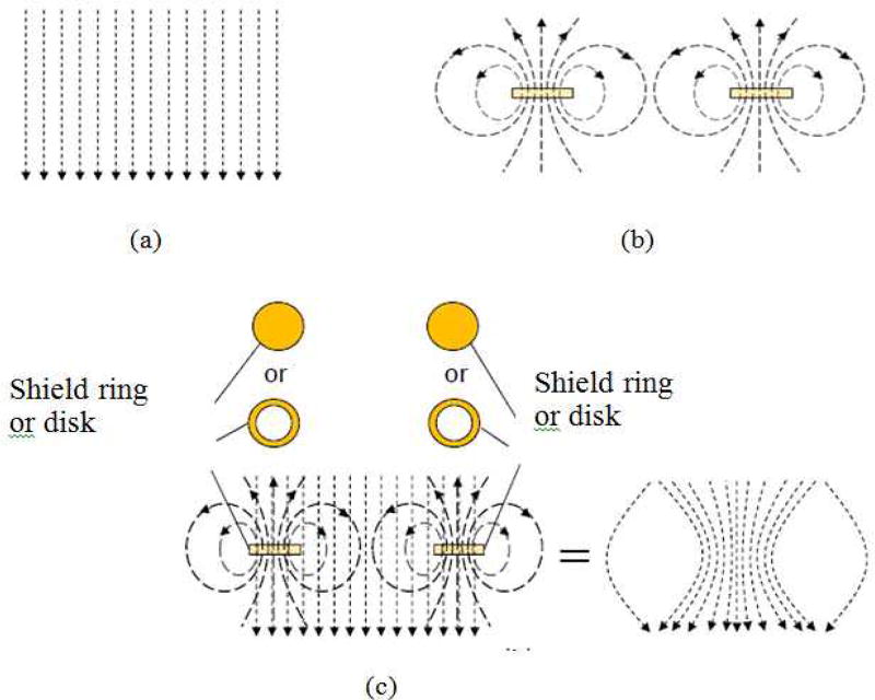
In traditional magnetic field focusing methods, a cone shape magnetic rod with variable diameter is usually used to first attract magnetic field and then focus the field by gradually reducing the diameter the rod. However, the diameter of the rod cannot be reduced to too small before magnetic field starts to leak out of the rod. Furthermore, since the magnetic field tends to quickly diverge right after it gets outside magnetic material into the air, the method cannot maintain a tightly focused field to the depth needed for brain stimulation. An alternative solution we adopted is to use induced eddy current generated second-order magnetic field and focality can be achieved from summation of first and second-order magnetic field distributions. This eddy current loop is induced to generate counter magnetic field that is against the primary field when the primary magnetic field is increasing and enhance the primary magnetic field when it is retreating according to Lenz’s Law. Since the induced current and induced electric fields are proportional to the changing rate of transient magnetic field (dB/dt), the secondary magnetic field plays the functions of both shielding and focusing. Figure 1 illustrates the field summation effect. By adjusting the locations of the shield disks or rings, optimized focusing effect can be accomplished with appropriate combination of the primary magnetic field and the eddy-current generated secondary magnetic field.
Fig. 1.
Principle of magnetic field shielding and focusing: (a). Primary transient magnetic field; (b). Second-order magnetic field generated by eddy current; (c). Superposition of the two fields. This represents the equivalent magnetic field lines after shielding. The middle part of the field distribution is focused.
B. Shield Design with Finite Element Analysis Tool (COMSOL)
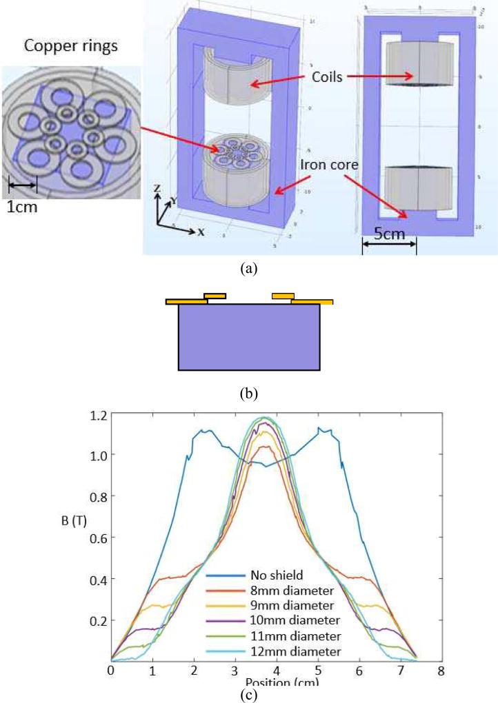
To verify the shield effect of the applied theory, a model that was similar to the experimental setup was built in COMSOL 5.2a, a finite element analysis tool, to simulate how copper ring arrays reshape magnetic field distribution generated by a pair of circular coils. Calculations in COMSOL were based on Maxwell equations and boundary conditions. In the model, as shown in figure 2 (a), the pair of coils are connected by iron cores and frame to reduce magnetic resistance. Each pole is 3.5cm in both length and width. The distance between two poles is 8cm and each coil has 1000 turns. In the simulation the shield formation consists 2 layers of copper ring arrays attached to each pole as shown in figure 2(b). Each layer consists of an array of 6 rings with 0.5mm layer thickness. The individual copper ring outer diameter in the large-ring layer is twice of small ring layer. For both the large and small rings, their inner diameter is one-half of their outer diameter. A very thin gap (0.1mm) between the two shield layers and the shield layer and pole was set to insulate the shield system. The system was analyzed with ‘fine’ mesh to obtain good spatial resolution. The AC current is set at 20 A amplitude and 1MHz frequency to drive each coil in the simulations. The setting of the operating frequency is to fit with the operation of experimental TMS driving pulses, which usually has a pulse rising time in the sub-microsecond level.
Fig. 2.
(a). COMSOL simulation of bi-pole structure coils with and without application of shield arrays (Gray colored objects are copper wire coil and copper rings shield array, and blue parts are the iron core and frame of the coil; however, its conductivity is adjusted to zero since the real experimental setup is using laminated iron sheets to inhibit eddy current in magnetic materials.); (b). The shield formation consists of two layers of ring arrays. Each layer has 6 stacks of rings arranged in a way to gradually reduce the formation opening; (c). Magnetic field distribution along x direction at a cut line 5mm above the pole without shield and field distributions at a cut line 5mm above the shield surface with the diameter of the shield formation opening of 8mm, 9mm, 10mm, 11mm and 12mm.
III. RESULTS
A. Simulation Results
The focality of magnetic field distribution was found to be highly dependent on the opening diameter of the shield array formation. In COMSOL simulation, the opening of the shield formation is adjusted with the outer diameter of rings in the small ring layer from 8mm to 12mm, while for each ring in the larger-ring layer, their outer diameter was also kept increasing to maintain a 2:1 ratio with that of the smaller rings. Magnetic field intensity was calculated along × direction, as shown in figure 2(a), that went through the central axis of the coils and 5mm above the shield top surface, since we are interested in areas around 5mm deep from rodent head surface into cortex. For an accurate comparison, we also calculate field distribution for the case without using a shield, which is 5mm away from the magnetic pole surface. Figure 2(c) shows that the larger the opening diameter of the shield formation, the stronger the peak magnetic field at the focal point. Compared with field distribution without shield, we can observe that not only the field is focused with a small focal spot size but also the field strength is enhanced for cases that the shield opening is larger than 10mm. Furthermore, as the diameter of shield opening increased, the generated magnetic beam profile became smoother and side lobes are further suppressed. The only drawback is that the field beam size tended to expand a little.
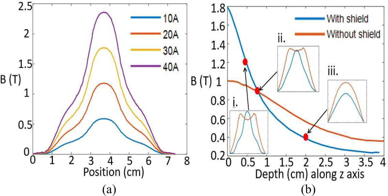
It was also found that the curve shape of magnetic field distribution was independent of overall current in the coil. As shown in figure 3(a), the peak value of magnetic field has a linear relation with the amount of current excitation. The magnetic field decay curves with and without the shield are shown in figure 3(b). It indicates that the shield’s field enhancement has an effective depth of 7.5mm or 8.7mm away from the iron core surface (8.7 = 7.5+2*[0.5+0.1]). It is not surprised that the induced dipole field from the ring array, can help to produce field enhancement in one region, will also reduce field strength in another region. With larger ring size and shield opening arrangement, the depth can be further increased but this may come with the price of larger spot size. Here 7.5mm depth is sufficient to reach many important regions of a mouse brain that we are interested in our stimulation experiments.
Fig. 3.
For the 12mm diameter shield, (a). Magnetic field distribution along the scanned line 5mm above the shield with variable current amplitude (number of turns was 1000 as a constant); (b). Comparison of magnetic field strength as a function of depth into tissue for cases of "with (blue)" and "without the shield (red curve)". Field decay curves are along z axis at x=0, y=0 (along the central axis of the two coils). Notice that for the case of "with the shield", the starting "0" position in the plot is at the shield surface, which is 5mm away from the iron pole surface. The field shall be significantly weaker without attaching shield to the coils. However, with the field summation effect, which also includes the additional induced field generated from the shield, it actually becomes 1.8 times higher than the field at the iron pole surface. The 3 inserted plots are the magnetic field distribution at the depth of i.0.5cm, ii.0.75 cm, and iii.2cm, respectively.
B. Experimental Setup Design and Results
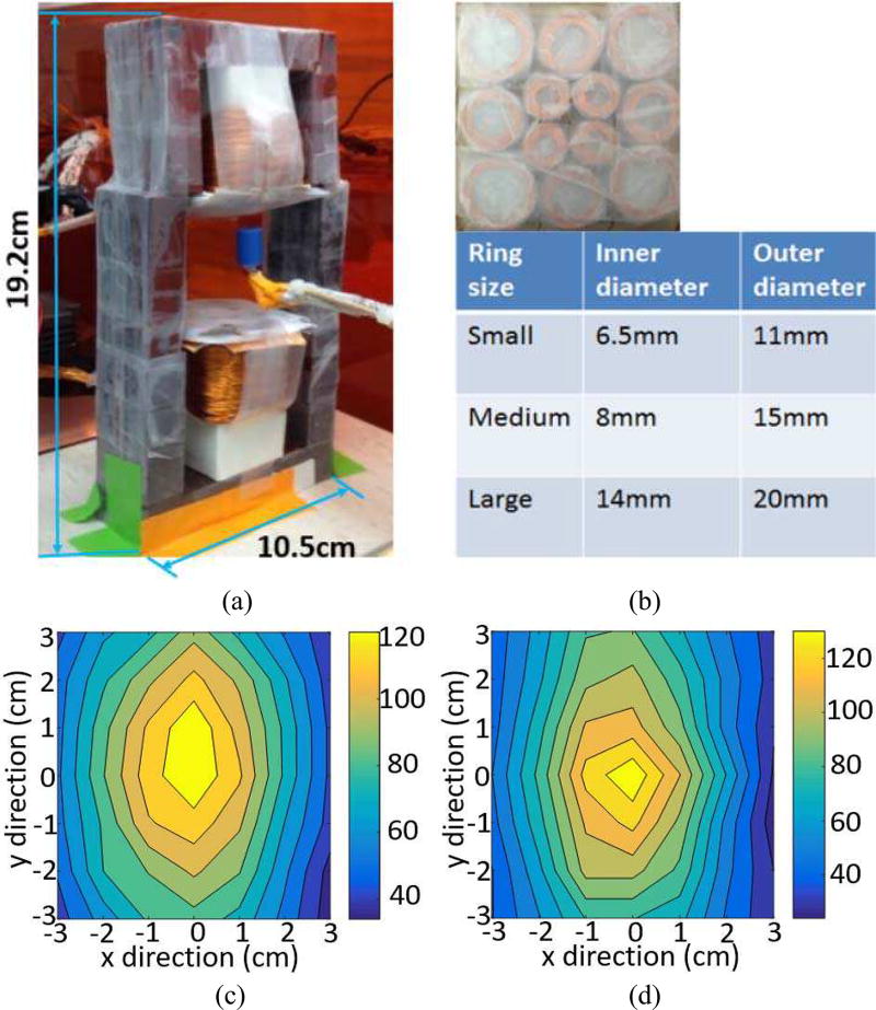
The experimental setup was constructed with laminated iron cores in figure 4(a) obtained from two electrical transformers, which has two poles, aligned in north-and-south arrangement and with an air gap distance of 8.5cm, enough space for even for rat brains. Compared with a one-pole system, a two-pole system has the advantage that its magnetic field will not incessantly diverge to open space. If no other manipulation technique is implemented the field will diverge first and then converge back symmetrically across the middle line of the two poles with a spindle shape distribution.
Fig. 4.
(a). Experimental setup of the rodents TMS coil (1000 turns); (b). Copper rings shield arrays experimentally designed in this study; (c). Magnetic field distribution contour plot of scanning without shield. The unit of color coding is in mV representing outputs from magnetic field probes; (d). Magnetic field distribution contour plot of scanning with the shield. (X axis: the direction from one iron wall to the other and perpendicular to the iron wall surface; Y axis: the direction perpendicular to X axis in the horizontal plane, as illustrated in figure 2(a).)
In this study, each pole was wrapped by equivalently 1000-turn (50 in parallel by 20 turns) coil made of 28-gauge copper wire. The shield is composed of copper ring arrays arranged in the geometric setting as shown in figure 4(b) to optimize the focusing. The total thickness of the shield layer was about 3mm with 3 single copper ring layers stacked together, and each single ring was insulated by varnish paint and very thin scotch tape. In operation, we can symmetrically attach shield to the top and the bottom poles surface. As shown in figure 2(a), the center of the shield was aligned with the center of the coil pole. The shield attachment reduces the stimulator inductance from 21.6 µH to 17.6 µH measured by inductance meter, as a result of the counter field generation. In our experiments, the excitation on coils was single pulses (400V, 100µs). With measurements using transient magnetic field probe (search coil type probe), we experimentally verified that at 400 VDC bias to the high voltage capacitor bank (1000µF) generated the magnetic field is equivalent to the field strength delivered at around 40% power by a typical commercial Magstim 200 systems. Measurements of Bz (perpendicular to the pole surface direction) were taken within the plane that was 5mm to the top shield surface (or 5mm to the pole surface if measured without shield). A 6cm by 6cm region was scanned and data was recorded every 1cm lateral spatial distance. The coil of the probe was in parallel with the two TMS coils. Since the transient magnetic field was under single pulse operation, no air cooling is needed for removing ohmic heating generated by eddy current in the shield.
After data was collected, the contour maps of 2-D field distributions were plotted in Matlab. Figure 4(c) shows the field strength contour map of the "without shield" case. It presents a canoe shape magnetic field distribution. This shape is caused by the two iron bars connecting the top and bottom parts of the stimulator framing structure. Since magnetic field is attracted toward magnetic material, the magnetic field distribution forms a long and narrow contour map around the center of the scanned plane. Figure 4(d) shows the field strength contour map of the "with shield" case. It has a relatively smaller focal spot with higher field strength. The contour lines circulating the highest field region was reshaped into an area of less than 5mm diameter. The magnetic field was enhanced by the shield at the center. So, even it is about 8 mm away from the iron pole surface, the field strength still increases due to the focusing effect as a result of field superposition. Compared with conventional figure-8 coil simulated by Xiong et al.[4], which indicated an equivalent focal spot size of wider than 1cm with various coil inductance.
IV. CONCLUSIONS
In this work we demonstrated magnetic focusing with focal spot size smaller than 5mm in diameter. By superposing the two-pole structure produced initial field and magnetic shield produced secondary field, we can obtain a focused combined field. The result implies that the shield technique can successfully achieve magnetic field focusing. It can be considered as a special case of individually controllable coil array, where each coil has the freedom to provide adjustable field polarity and strength to obtain optimized field focusing. However, it is expensive to implement such an individually controllable coil array considering the current commercial TMS system is typically cost over $50k for a single coil and driver stimulator system. The shield stimulator system we proposed and demonstrated here provides a practical and low cost solution to achieve well focused stimulation and its practicality in the current status of development is geared towards application to studies on rodents and other small animals.
Acknowledgments
The research is supported by the intramural research program of NIDA/NIH and NSF award number ECCS-1631820.
References
- 1.Roth Y, Amir A, Levkovitz Y, et al. Three-dimensional distribution of the electric field induced in the brain by transcranial magnetic stimulation using figure-8 and deep H-coils. J Clin Neurophysiol. 2007 Feb;24(1):31–38. doi: 10.1097/WNP.0b013e31802fa393. [DOI] [PubMed] [Google Scholar]
- 2.Deng Z-D, Lisanby SH, Peterchev AV. Coil design considerations for deep transcranial magnetic stimulation. J ClinNeurophysiol. 2014 Jun;125(6):1202–1212. doi: 10.1016/j.clinph.2013.11.038. [DOI] [PMC free article] [PubMed] [Google Scholar]
- 3.Deng Z-D, Lisanby SH, Peterchev AV. Electric field depth focality tradeoff in transcranial magnetic stimulation: Simulation comparison of 50 coil designs. Brain Stimul. 2013 Jan;6(1):1–13. doi: 10.1016/j.brs.2012.02.005. [DOI] [PMC free article] [PubMed] [Google Scholar]
- 4.Xiong H, Shi J-H, Hu X-W, et al. The focusing optimization of transcranial magnetic stimulation system. Prog Electromagn Res. 2016;48:145–154. [Google Scholar]
- 5.Koenigs M, Grafman J. The functional neuroanatomy of depression: distinct roles for ventromedial and dorsolateral prefrontal cortex. Behav brain res. 2009 Aug;201(2):239–243. doi: 10.1016/j.bbr.2009.03.004. [DOI] [PMC free article] [PubMed] [Google Scholar]
- 6.Lisanby SH, Belmaker RH. Animal models of the mechanisms of action of repetitive transcranial magnetic stimulation (RTMS): comparisons with electroconvulsive shock (ECS) Depress Anxiety. 2000 Nov;12(3):178–187. doi: 10.1002/1520-6394(2000)12:3<178::AID-DA10>3.0.CO;2-N. [DOI] [PubMed] [Google Scholar]
- 7.Alotto P, Guarnieri M, Moro F. A boundary integral formulation on unstructured dual grids for eddy current analysis in thin shields. IEEE T Magn. 2007 Apr;43(4):1173–1176. [Google Scholar]
- 8.Feliziani M, Maradei F. Finite-difference time-domain modeling of thin shields. IEEE T Magn. 2000 Jul;36(4):848–851. [Google Scholar]
- 9.Kim D-H, Georghiou GE, Won C. Improved field localization in transcranial magnetic stimulation of the brain with the utilization of a conductive shield plate in the stimulator. IEEE T BIO-MED ENG. 2006 Apr;53(4):720–725. doi: 10.1109/TBME.2006.870244. [DOI] [PubMed] [Google Scholar]
- 10.Zhang S, Yin T, Liu Z, et al. Experimental study to improve the focalization of a figure-eight coil of rTMS by using a highly conductive and highly permeable medium. IEEE T NEUR SYS REH. 2013 May;21(3):364–369. doi: 10.1109/TNSRE.2012.2194723. [DOI] [PubMed] [Google Scholar]
- 11.Zhao C, Zhang S, Liu Z, et al. Simulation study to improve focalization of a figure eight coil by using a conductive shield plate and a ferromagnetic block. IEEE T NEUR SYS REH. 2015 Jul;23(4):529–537. doi: 10.1109/TNSRE.2015.2389263. [DOI] [PubMed] [Google Scholar]


