Abstract
The orientation and stability of the reconnection x line in asymmetric geometry is studied using three-dimensional (3-D) particle-in-cell simulations. We initiate reconnection at the center of a large simulation domain to minimize the boundary effect. The resulting x line has sufficient freedom to develop along an optimal orientation, and it remains laminar. Companion 2-D simulations indicate that this x line orientation maximizes the reconnection rate. The divergence of the nongyrotropic pressure tensor breaks the frozen-in condition, consistent with its 2-D counterpart. We then design 3-D simulations with one dimension being short to fix the x line orientation but long enough to allow the growth of the fastest growing oblique tearing modes. This numerical experiment suggests that reconnection tends to radiate secondary oblique tearing modes if it is externally (globally) forced to proceed along an orientation not favored by the local physics. The development of oblique structure easily leads to turbulence inside small periodic systems.
1. Introduction
Magnetic reconnection plays the critical role in the plasma transport and magnetic energy release at Earth’s magnetopause, the sharp boundary separating Earth’s magnetosphere and solar wind plasmas. To understand the global convection of plasmas and magnetic flux around Earth, it is imperative to know where reconnection will take place on this boundary layer (Dungey, 1961). With purely southward interplanetary magnetic fields in the solar wind, it is clear that the dayside reconnection will occur along the equatorial plane. The resulting locus that connects these reconnection locations is called the reconnection line (e.g., Trattner et al., 2004). However, the location and orientation of the reconnection line become less clear when the interplanetary magnetic field points in a clock angle different than southward (i.e., the Sun-Earth direction is the rotation axis). Observations suggested a”tilted” reconnection line in this situation (Daly et al., 1984; Dunlop, Zhang, Bogdanova, Lockwood, et al., 2011; Dunlop, Zhang, Bogdanova, Trattner, et al., 2011; Fear et al., 2012; Kawano & Russell, 2005; Phan et al., 2006; Pu et al., 2007; Scurry et al., 1994; Trattner et al., 2007; Wild et al., 2007). A similarly tilted reconnection line was illustrated in global magnetohydrodynamics simulations by tracing the global magnetic separator (Komar et al., 2013). Predictions of the reconnection line location on the magnetopause were previously made by mapping out locations that maximize local quantities, such as the shear angle (Trattner et al., 2007), current density (Alexeev et al., 1998), and Poynting flux divergence (Papadopoulos et al., 1999). Another approach was based on the vacuum superposition of Earth dipolar and solar wind magnetic fields (Cowley, 1973; Dorelli et al., 2007; Siscoe et al., 2001).
In this work, we approach this problem from the local aspect of reconnection by studying the orientation of the reconnection x line in slab geometry. Even with this simplified geometry, understanding this 3-D nature of magnetic reconnection is already challenging and a strict theoretical treatment does not exist. Researchers have used the same principle that determines the local x line orientation to map out the reconnection location on the global magnetopause (Komar et al., 2015). The result of this study suggests that the tangent of a global reconnection line will eventually align with the local x line orientation. The question to solve and the coordinate system employed in this study are further illustrated in Figure 1. Magnetic fields on two sides of the boundary layer (like Earth’s magnetopause) can shear at an arbitrary angle $. Here we consider the boundary normal to the z direction and the Bz component to be negligible. If we take a 2-D cut depicted by the black line in Figure 1a, the in-plane component of magnetic fields on the two sides are antiparallel as illustrated in Figure 1b, and thus reconnection can occur on this plane. However, this 2-D plane is not the only possible choice. We take another 2-D plane in Figure 1c, and there are also in-plane antiparallel magnetic fields for reconnection as illustrated in Figure 1d although the in-plane field strength changes on this plane. Therefore, the question to ask is, given different magnetic field and plasma conditions on two sides of the current sheet, on which plane will reconnection proceed? Since the reconnection x line (marked by the orange dashed line in Figures 1a and 1c) is always perpendicular to the corresponding 2-D reconnection plane, the goal is equivalent to determining the orientation of the x line. We will quantify the x line orientation by the angle 6 respected to the y0 axis (for simplicity, we choose y0 to be the direction where the guide field By0 is uniform). Hypotheses to this well-defined question were proposed. They include minimizing the in-plane current (Gonzalez & Mozer, 1974; Sonnerup, 1974), maximizing the reconnection outflow speed (Swisdak & Drake, 2007), maximizing the reconnection rate (Aunai et al., 2016; Hesse et al., 2013; Liu et al., 2015; Schreier et al., 2010), or maximizing the oblique tearing growth rate (Liu et al., 2015). On the other hand, other than a few studies in literature (Liu et al., 2015; Schreier etal., 2010), there are not many attempts to study this fundamental nature of magnetic reconnection using first-principle 3-D simulations. To resolve the reconnection x line in the electron scale will require a fully kinetic description. Thus, we use both 3-D and 2-D particle-in-cell (PIC) simulations to explore this issue. After knowing the optimal orientation favored by the local physics, we further study the response of the system when the x line is forced to misalign with the optimal orientation. This result reveals the potential format of the interplay between the global and local controls.
Figure 1.
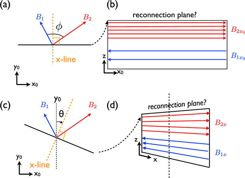
Illustration of the question to solve.
The structure of this paper is outlined in the following. Section 2 describes the simulation setup. Section 3 measures the x line orientation in the large 3-D simulation. Section 4 identifies the nonideal term in Ohm’s law that breaks the frozen-in condition. Section 5 shows the comparison with companion 2-D simulations and theories. Section 6 studies the response of the x line when it is forced to proceed at an orientation not favored by the local physics. Section 7 summarizes and discusses our results.
2. Simulation Setup
In this paper, kinetic simulations were performed using the electromagnetic PIC code VPIC (Bowers et al., 2009). The employed asymmetric current sheet (Aunai, Hesse, Zenitani etal., 2013; Hesse etal., 2013; Liu etal., 2015; Pritchett, 2008) has the magnetic profile, with , which corresponds to a shear angle across the sheet. This profile gives and where the subscripts “1” and “2” correspond to the magnetosheath and magnetosphere sides, respectively. The initial current sheet has a half thickness L = 0.8d, and it is shifted from z = 0 to z = 3di, to accommodate the larger structure expected in the weaker field side; the opening angle of the reconnection exhaust boundary on this side should be larger (Liu et al., 2018). The plasma has a density profile that gives and . The uniform total temperature is that consists of contributions from ions and electrons with ratio . The mass ratio is . The ratio of the electron plasma to gyrofrequency is where and . In the presentation, densities, time, velocities, spatial scales, magnetic fields, and electric fields are normalized to n0, the ion gyrofrequency Ωcl, the Alfvénic speed , the ion inertia length and , respectively.
The x line orientation will be quantified by the angle 6 respect to the y0 axis illustrated in Figure 1. A clockwise rotation gives a negative θ. We can rotate the simulation box along the z axis by θbox so that and . The resulting magnetic field in the new coordinate will be
| (1) |
In a 2-D system, the orientation of the x line is fixed in the out-of-plane direction. This machinery allows us to study reconnection at a given x line orientation θ = θbox.
The primary 3-D case has θbox = 0°,and it has a domain size , and 4,096×4,096× 384 cells. The boundary conditions are periodic both in the x and y directions, while in the z direction they are conducting for fields and reflecting for particles. We use 200 particles per cell. Adopting the methodology in Liu etal.(2015),we localize the perturbation in both thexandy directions to initiate reconnection. Companion 2-D and 3-D simulations with a much shorter y extent at a few representative oblique angles θbox are designed to compare and contrast with the primary 3-D case.
3. X Line Orientation
Magnetic reconnection is initiated at the center of the simulation domain. The reconnection x line forms and spreads. In a slab geometry, a reconnection x line is best defined by the line of vanishing Bz, which is sandwiched between newly generated reconnected field Bz. The peak current density also serves as a good proxy to study the x line orientation when the x line is quasi-2-D (Liu et al., 2015). The total current density |J| at y = 0 and time 184/Ωci is shown in Figure 2a. To study the orientation of this x line, we then take the x-y cut of a few quantities across the location of the intense current at . The current density in Figure 2b captures the distinct x line that is microscopically narrow but macroscopically long on the x-y plane. A movie that shows the evolution of |J| can be found in the supporting information. The x line in this case is surprisingly laminar and quasi-2-D, unlike most 3-D simulations where turbulence impacts the current sheet. The large guide field has suppressed the drift-kink instability (Karimabadi et al., 2003). The mild variability of the x line occurs when the intense current spreads and merges with the current intensified by the background tearing modes at two ends of this primary x line. For reference, the orientations of the asymptotic magnetic fields on both sides are marked by the yellow dashed arrows. The field strength is proportional to the arrow length. A straight line at orientation −13° is also plotted for comparison. This is the x line orientation previously determined by the simulation in a 4 × 4 × 1.5 smaller spatial domain (illustrated by the green dashed box at the upper right corner of Figure 2b) and 3 times shorter evolution time (60/Qci) (Liu et al., 2015). In conjunction with Liu et al. (2015), the comparison demonstrates that this well-defined x line sustains the same orientation for at least (184 – 60)/Ω.cl = 124/Ω.cl, and we do not expect this orientation to change in a larger simulation. While the x line extent in Liu et al. (2015) is , the x line in this larger simulation spread to a spatial length , suggesting that the x line extent in this regime is purely limited by the system size and there is no intrinsic length limitation in the 3-D system. In a slab geometry, the reconnected magnetic field Bz normal to the current sheet most faithfully captures the x line because it marks the change of the field-line connectivity. The Bz reversal in Figure 2 shows a similar orientation. The Alfvenic flow reversals serve as the strong indicative evidence of magnetic reconnection in in situ observations (e.g., Burch et al., 2016). The locus of outflow reversal locations, as captured by Vex and Vix in Figures 2d and 2e, also suggests a similar orientation. Also, note that in Figure 2c the clear stripe structure of Bz arises from the dominant oblique tearing modes that spontaneously grow from the ambient current sheet. The associated plasmoids are observed in Figure 2a for |x| ≳ 75d, outside of the outflow region of the primary reconnection x line. These stripes make a similar orientation at −13°, and this fact has an implication for the x line stability that will be discussed later.
Figure 2.
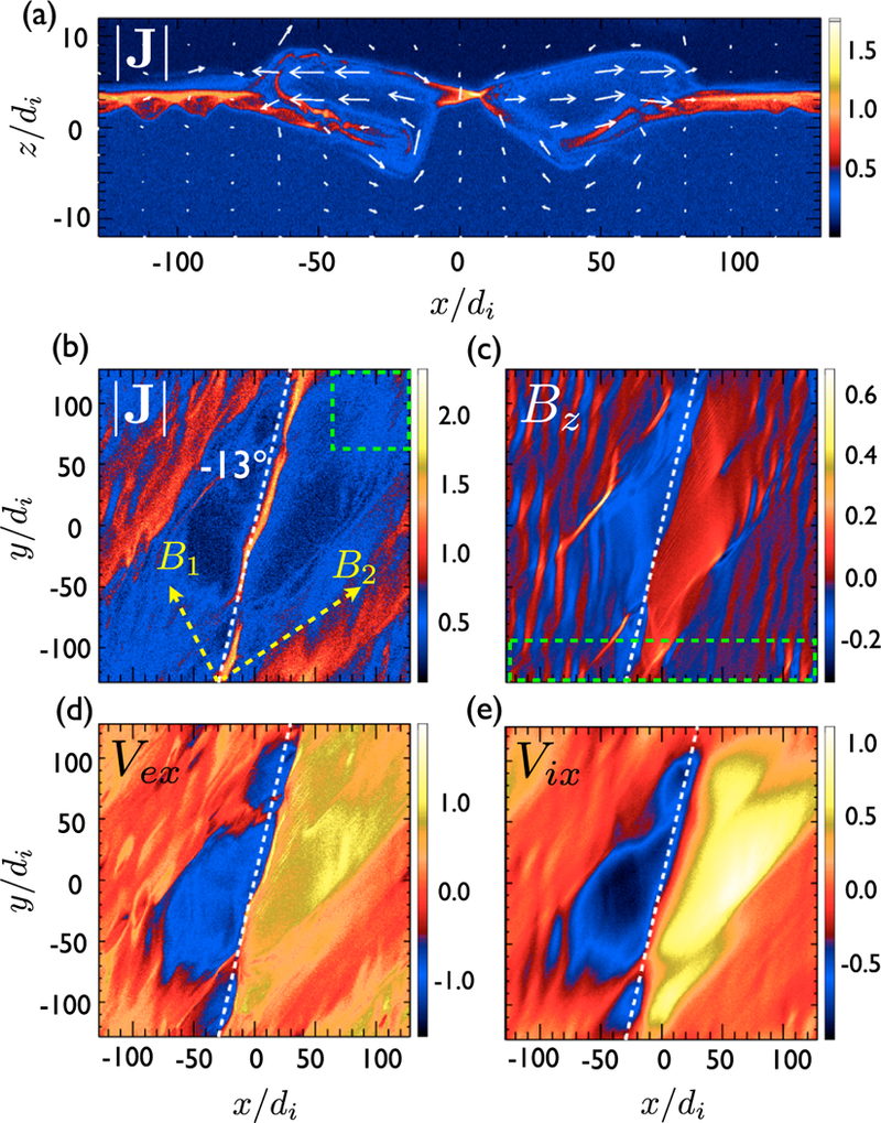
Quantities at time 184/Ωci. In (a) the total current density |J| on a 2-D plane where y = 0. The white arrows show the in-plane electron velocities. In (b) the x-y cut of |J| across the location of the intense current near the x line. Similarly, in (c), the reconnected field Bz; in (d), the electron outflow Vex; and in (e), the ion outflow Vix. On top of the figures, yellow arrowed lines in (b) illustrate the magnetic fields on two sides of the current sheet, and white dashed lines in (b)-(e) have 9 = −13°.
4. Break of the Frozen-in Condition
The sharp spatial gradient adjacent to the electron-scale diffusion region makes the ambient plasmas nongyrotropic. Figure 3a shows the nongyrotropy calculation (Aunai, Hesse & Kuznetsova 2013) where the nongyrotropy tensor measures the difference between the full pressure tensor and its gyrotropic approximation. Here with being the electron pressure parallel to the local magnetic field and being the pressure perpendicular to the local magnetic field. The intense Dng traces the diffusion region and the sharp outflow exhaust boundaries. To assess the break of the electron frozen-in condition, we analyze the composition of the nonideal electric field (along the vertical white dashed line) using the electron momentum equation (i.e., Ohm’s law)
| (2) |
Figure 3.
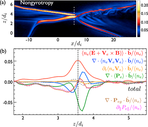
In (a) the measure of the nongyrotropy (Dng) of the pressure tensor. In (b) the decomposition of the nonideal electric field. The charge e and electron mass me are normalized to unity in our presentation.
In order to beat the PIC noise in this calculation, it is customary to ensemble average quantities. Since the meaning of “anomalous dissipations” arising from an ensemble average (either in a given space extent; Che et al., 2011; Le et al., 2017; Price et al., 2016 or time duration; Le et al., 2017) remains unclear (Le et al., 2018), here we average the entire equation without further splitting the nonlinear terms into a product of averaged quantities. The ensemble-averaged quantities are marked by the angle bracket in Figure 3b. indicates that the entire quantity Q is time averaged using 1,000 frames within duration 1.7/Ω.ci, then it is dotted with the averaged unit magnetic vector . This shows the (time-averaged) quantity in the (time-averaged) parallel direction.
The peak nonideal electric field in the parallel direction is primarily supported by the pressure tensor (green), and it closely resembles that in the corresponding 2-D simulation (Hesse et al., 2016; Lu et al., 2013). To further identify the key contribution in the full pressure tensors, it is useful to evaluate the divergence of its gyrotropic approximation. A similar decomposition is also analyzed in the observations of Magnetospheric Multiscale (MMS) mission (Genestreti et al., 2018; Rager et al., 2018). Outside of the diffusion region, (brown) is a good approximation of . The contribution from the gyrotropic approximation vanishes near the location of the peak nonideal electric field, indicating that the primary contribution to the pressure gradient comes from the nongyrotropy. This is consistent with the idea made by the Dng measurement in Figure 3a. We can further decompose the gyrotropic pressure gradient into In where . The simulation result suggests that the gyrotropic contribution can be approximated by . That is, the parallel gradient of the parallel component of the pressure tensor (magenta diamonds). The validity of this approximation is also observed in previous 3-D simulations (Liu et al., 2013).
5. Companion 2-D Simulations and Theories
Unlike the 3-D system where the x line has sufficient freedom to choose an optimal orientation, in 2-D systems the orientation of the x line is always fixed to the out-of-plane direction because of the translational invariance along this direction. Taking advantage of this artifact, we can study the property of reconnection in a specified orientation. On different oblique planes, the strength of the in-plane magnetic field varies according to equation (1). The in-plane component of magnetic field reverses sign for θbox ϵ [−56.3°, 26.6°], and reconnection could operate on any of these oblique planes. In Figure 4a, we show the evolution of reconnection rates on few oblique planes ranging from θbox = −25° to 10°. These rates are measured by calculating the change of the in-plane magnetic flux in between the X and O points. The measurement suggests that the reconnection rate is maximized at the orientation around −13° (red curve in Figure 4a), consistent with the orientation manifested in the 3-D simulation. This comparison between 3-D and 2-D systems demonstrates that reconnection proceeds near the maximal reconnection rate. (As an aside, this tendency of maximizing the rate revealed in 3-D simulations echoes the hypothesis used to derive the normalized asymmetric reconnection rate 0.1 in recent work Liu et al., 2018.)
Figure 4.
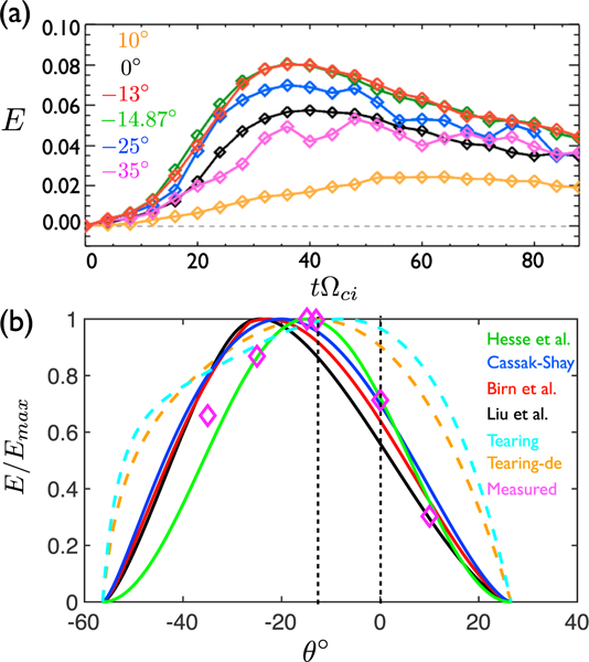
In (a) the evolution of the reconnection rate (E) measured on a sample of oblique planes at different θbox. In (b), “Hesse et al.,” “Cassak-Shay,” “Birn et al.,” and “Liu et al.” are the predicted reconnection rates from different models. “Tearing” shows the tearing growth rate derived in Appendix A and “Tearing-de” is the modified growth rate in a de scale sheet. The measured rates from (a) are plotted as magenta diamonds. Each curve is normalized to its maximum value.
Prompted by this agreement, we now compare our results to the prediction from different rate models. Cassak and Shay (2007) derived an expression of reconnection rate based on conservation laws, . Later, Birn et al. (2010) included the effect of compression and enthalpy in the calculation. Hesse etal. (2013) proposed that the reconnection rate is proportional to the available magnetic energy based on the reconnecting component , which always leads to a maximal rate at the bisection angle. Recently, Liu etal. (2018) modeled the reconnection rate as a function of the opening angle made by the upstream magnetic field. A prediction is attained by maximizing the model rate under the geometrical constraint imposed at the magnetohydrodynamics scale. Finally, since the stripe made by the dominant oblique tearing modes (presumably the fastest growing tearing modes) appears to be parallel to the x line orientation (Figure 2c), we also derive the growth rate of collisionless oblique tearing modes in Appendix A. It is not too surprising to see the dominant tearing mode sharing an orientation similar to that of the x line at its nonlinear state, because a tearing mode is the linear stage of spontaneous reconnection. As demonstrated in the next section, the fastest growing oblique tearing becomes active when the x line is forced to be oriented at an angle different from the optimal orientation.
These predicted reconnection rates are plotted in Figure 4b as a function of the x line orientation θ. To facilitate the identification of the optimal angle, each curve is normalized to its maximum. For reference, θ = −13° (the x line orientation) and 0° (the y0 axis) are marked by the vertical dashed lines. We also plot the peak reconnection rates measured in Figure 4a as magenta diamonds. The linear growth rates of oblique tearing modes are plotted as a cyan dashed curve. The growth rate based on a thick current sheet maximizes at . However, secondary tearing modes often grow from the nonlinear current sheet of de scale thickness and the tearing-mode simulation in a de scale sheet (Liu etal., 2015) showed the dominant mode with an orientation close to . After accounting fora narrow sheet at de scale, a modified theory (also derived in Appendix A) is plotted as the orange dashed curve. Two of the closest predictions of the x line orientation for this case are provided by Hesse etal. (2013) at the bisection angle and the maximum of the modified tearing growth rate at . To distinguish which model works better in general will require a thorough parametric study. Nevertheless, these predictions range from 0 ~ −8° to −25° and are clearly off they0 axis at 0 = 0°. The observed x line orientation falls within this predicted range.
6. Orientation Versus Stability—A Numerical Experiment
At Earth’s magnetopause, the initial reconnection line could be preconditioned by the global geometry and external forcing when a relatively planar solar wind touches the bell-shaped magnetosphere at the dayside. The local tangent of such a reconnection line may not necessarily align with the optimal orientation favored by the local physics. It is thus interesting to explore the stability of reconnection in a 3-D system when the x line does not point to the optimal orientation. As mentioned earlier, when the Ly boundary is extremely short, the quasi-2-D system fixes the x line to the y direction and completely suppresses any mode that has a finite ky. In the following numerical experiments, we make Ly short to fix the x line in the y direction but long enough to allow the development of oblique tearing modes, which can spontaneously lead to competing reconnecting modes at different orientations.
In order to fit one oblique tearing mode of wavelength A at orientation inside the simulation domain, it requires (see Appendix B), and this wavelength needs to satisfy for the unstable condition of tearing modes (i.e., calculated in the Appendix A). For an oblique tearing mode to grow at the optimal orientation in the initial current sheet of , it requires . The fastest growing mode typically has a wave number around , and this will require . Thus, we choose , that should provide sufficient room for the oblique tearing mode to grow at this optimal orientation if its growth is desired. This y extent is 8 times shorter than the primary 3-D case, as illustrated by the green dashed box marked in Figure 2c. In addition, we apply a perturbation that is uniform in the y direction to initiate the x line.
In the first case, we keep . The evolution of reconnection is shown in Figure 5. The color shows the electron velocity Vey. The most pronounced feature is the turbulence in Figures 5c and 5d, which is absent in the large 3-D case (Figure 2). Here we explain what gives rise to this turbulence. First of all, note that the primary x line points more or less in the y direction as initiated by the perturbation and soon enforced by the periodic boundary condition in the y direction. However, secondary tearing modes emerge on top of the primary x line in Figures 5a and 5b. These tearing modes are oblique to the primary x line in the y direction, as illustrated by the Bz structure on the x-y plane in Figures 8a and 8b. Not too surprisingly, this structure is parallel to the optimal orientation at as marked by the white dashed line. The system radiates secondary tearing modes to adjust the orientation, but this attempt is destined to fail because of the large-scale orientation enforced by the periodic y boundary. The fast-streaming electrons resonated by tearing modes form intense electric current, which needs to close itself since in the nonrel-ativistic limit. The intense current structure leaves one y boundary at an oblique angle will come back from the other side farther downstream, forming a tearing chain along the entire separatrix and constantly feeding complexity back to the periodic system. In contrast, the x line and separatrix are quiet in the primary 3-D case (Figure 2).
Figure 5.
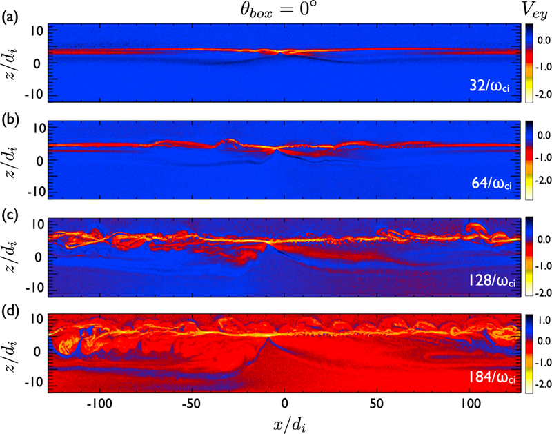
The evolution of reconnection in a companion 3-D simulation using Ly = 32di, and θbox = 0°. The color shows the electron flow speed in the y direction (Vey).
Figure 8.
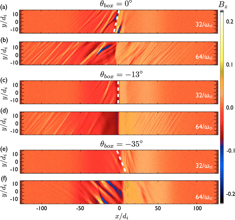
The Bz structure in the x-y plane that contain the x line in companion 3-D simulation using Ly = 32di.In (a) and (b) θbox = 0°, in (c) and (d) θbox = −13°, and in (e) and (f) θbox = −35°. The white dashed lines mark the orientation (θ = −13°) favored by the local physics.
In the second case, we rotate the simulation box to so that the y axis is along the optimal x line orientation. The evolution is shown in Figure 6. A secondary tearing mode appears in Figure 6a and soon disappears in the outflow. This secondary tearing mode forms structure parallel to the y direction, as expected, and it is easier to be advected out coherently and be merged in the outflow. The reconnection x line is thus considerably less turbulent. Oblique modes of smaller spatial scale later develop along the separatrix further downstream (Figure 6c). These modes could be lower hybrid drift modes or weaker oblique tearing modes. They eventually spread out and reach the x line (Figure 6d), perhaps, due to the combination of the x and y periodic boundaries. In the third case shown in Figure 7, we rotate the simulation box to . Secondary tearing modes emerge and linger around the x line. This case further confirms that the secondary tearing modes do emerge along the optimal x line orientation, as shown in Figures 8e and 8f. Note that since the primary outflow speed driven by the preselected x line only varies as a function of the x location, segments on an oblique structure at different x locations are thus advected in different speeds (before the entire structure enters the region of a uniform Alfvenic outflow). Thus, the tilt angle of the oblique structure can become larger further downstream.
Figure 6.
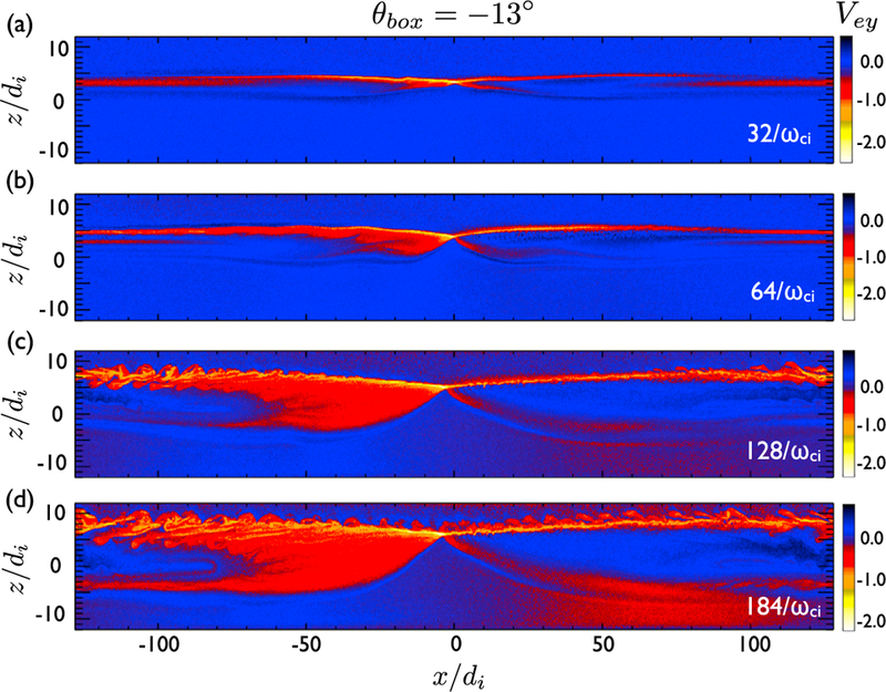
The evolution of reconnection in a companion 3-Di simulation using Ly = 32d, and θbox = −13°. The color shows the electron flow speed in the y direction (Vey).
Figure 7.
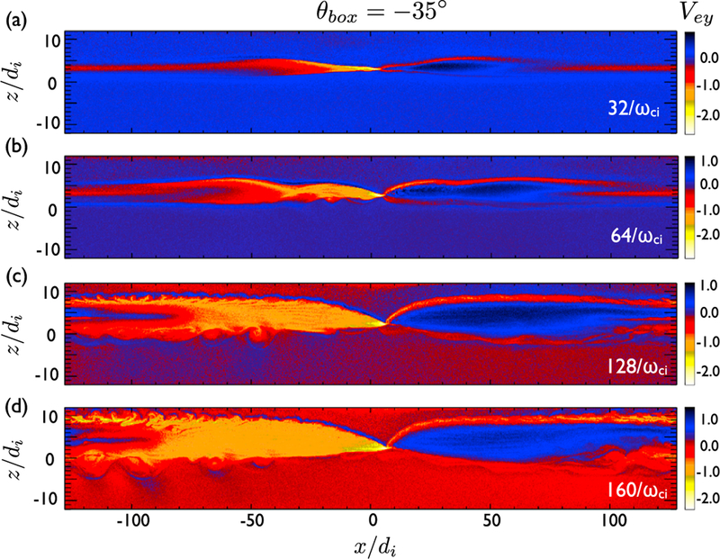
The evolution of reconnection in a companion 3-D simulation using Ly = 32di, and θbox = −35°. The color shows the electron flow speed in the y direction (Vey).
In short, these numerical experiments suggest that when the primary x line is forced to point at an orientation not favored by the local physics, the system radiates oblique tearing modes to adjust itself. The resulting oblique structure makes reconnection difficult to regain a coherent quasi-2-D structure inside a small periodic box.
7. Summary and Discussion
We studied the x line orientation and its stability using PIC simulations, showing that the x line in a large 3-D system (i.e., a proxy of an open system) proceeds along the orientation that maximizes the reconnection rate. The resulting diffusion region is laminar and the nongyrotropic feature of the pressure tensor breaks the frozen-in condition. In contrast, when the x line is externally forced to misalign with this optimal orientation, secondary oblique tearing modes develop to adjust the orientation. Inside a small periodic system, the oblique structure can hardly be expelled and merged. The fast-streaming electrons resonated by tearing modes quickly spread over the entire system, constantly feeding complex structure back to the periodic system and leading to turbulence. Based on these numerical experiments, we conclude that the reconnection x line needs not be as turbulent as observed in small periodic simulations.
At Earth’s magnetopause, a global reconnection line that misaligns with the optimal orientation favored by the local physics is expected to radiate secondary oblique tearing modes. However, the relatively large system may provide a sufficient room for the x line to adjust its orientation and to resume its natural, quieter state. To accurately model this reaction would require more realistic initial conditions, boundary conditions, and global external drives that are not yet feasible in a full PIC simulation. One possibility is that a misaligned reconnection line will breakup into smaller segments, which each are ideally aligned. This could explain localized bursts of reconnection in connection with flux transfer events. Note that the turbulence driven by the lower hybrid drift instability (LHDI) was discussed in MMS observation (Ergun et al., 2016; Graham et al., 2017) and the associated event studies using 3-D PIC simulations (Le et al., 2017; Price et al., 2016). For the parameters studied in this case, the LHDI appears to be relatively weak at the x line as shown in Figure 2a or 3a. The effect of LHDI on the x line is not the focus in this work, but the potential boundary effect inside a small periodic system also deserves future investigation. Note that this work does not imply that the generation of secondary flux ropes is entirely excluded when the x line develops along the optimal orientation. For instance, flux ropes were observed in the vicinity of the x line during tail reconnection (Wang et al., 2015,2010). Instead, this work suggests that an x line is inclined to generate secondary tearing modes when it misaligns with the optimal orientation.
We emphasize that an important nature of magnetic reconnection is revealed in this 3-D simulation; the comparison between the observed orientation and companion 2-D simulations in Figure 4a shows that reconnection tends to proceed at or, at least, near the maximal reconnection rate. This fact can be crucial for the explanation of the fast rate value of order 0.1; a recent model (Liu et al., 2017,2018) suggests that the reconnection rate profile as a function of the opening angle made by the upstream magnetic field is relatively flat near this optimal state, and it has a value of order 0.1.
In summary, this study advances our understanding of the 3-D orientation and stability of the asymmetric reconnection x line. This result could help interpret the local geometry of reconnection events observed by MMS and, perhaps, help determine an appropriate LMN coordinate (Denton et al., 2018). The question we are exploring is also relevant to the upcoming European Space Agency-Chinese Academy of Sciences joint mission, Solar wind Magnetosphere Ionosphere Link Explorer, which will study the development of reconnection lines at Earth’s magnetopause using X-ray and ultraviolet imagers.
Supplementary Material
Key Points:
The orientation of asymmetric reconnection x line is studied using large 3-D particle-in-cell simulations
Companion 2-D simulations indicate that the 3-D system selects a state of, or at least near, the maximal reconnection rate
The system tends to radiates secondary oblique tearing modes when the primary x line is forced to misalign with this optimal orientation
Acknowledgments
Y.-H. Liu is supported by NASA grant NNX16AG75G. M. Hesse acknowledges support by the Research Council of Norway/CoE under contract 223252/F50 and by NASA’s MMS mission. Simulations is supported by NSF-Petascale Computing Resource Allocation project no. ACI1640768 on Blue Waters, NASA Advanced Supercomputing, and NERSC Advanced Supercomputing. The large date generated by petascale PIC simulations can hardly be made publicly available. Interested researchers are welcome to contact the leading author for subset of the data archived in computational centers. A movie that shows the evolution of the x line can be found in the supporting information.
Appendix A:
Collisionless Tearing Growth Rate
In addition to obtaining an optimal orientation by maximizing the reconnection rate, it is also interesting to consider the competition of linear tearing modes that lead to spontaneous reconnection.
We consider the collisionless tearing stability of this configuration for an arbitrary wavevector corresponding to oblique angle and resonance surface , at • B = 0. In the outer region, the magnetohydrodynamic model is used to obtain an eigenmode equation (Furth et al., 1963) of the form , where is the perturbed flux function at the oblique plane and . By combining the approximate solutions for and in the same manner as in Baalrud et al. (2012), we get the drive for tearing perturbations (Furth et al., 1963) where . Plugging in our configuration, it gives
| (A1) |
The upper bound of the unstable wave number is . Using the standard matching approach (Daughton et al., 2011; Drake & Lee, 1977) to the kinetic resonance layer gives
| (A2) |
where is the electron thermal speed and de = c/wpe is the local electron inertial length at the resonant surface. ls is the scale length of the magnetic shear defined in . It is derived to be
The dominant mode typically has a wavelength , and it is roughly 0.5. Based on this wave number (kc/2), the growth rate at the different oblique angle is shown by the dashed cyan curve in Figure 4b, which has a maximum at .
The width of the resonant surface A is determined by the resonant condition (Drake & Lee, 1977) and it should be limited by the thickness of the current sheet L. Thus, by comparing with equation (A2) we can derive . For , we have . On the other hand, equation (A1) with suggests in the same limit. It is thus clear that the theory breaks down for a narrow sheet L/de < 1. As a quick remedy, we argue , and thus, . This modified rate fora de scale sheet is plotted as the orange dashed curve in Figure 4b, which has a maximum at , comparable to the oblique angle of the dominant mode observed in a de scale sheet (Liu et al., 2015).
Appendix B:
The Minimum Box Size Required for an Oblique Mode
To perfectly fit an oblique mode of angle 0 and wavelength X inside a box of periodic y boundary, as shown in Figure B1, it requires where N is a positive integer. For , the mode can at least partially manifest its orientation. For Ly < λ/sinθ, such a mode is impossible to grow due to the effect of the periodic boundary.
Figure B1.
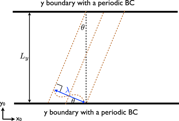
The system size Ly that perfectly fit an oblique mode of angle θ and wavelength λ.
References
- Alexeev II, Sibeck DG, & Bobrovnikov SY (1998). Concerning the location of magnetopause merging as a function of the magnetopause current sheet. Journal ofGeophysical Research, 103(A4), 6675–6684. [Google Scholar]
- Aunai N, Hesse M, & Kuznetsova M (2013). Electron nongyrotropy in the context of collisionless magnetic reconnection. Physics of P/asmas, 20,92903. [Google Scholar]
- Aunai N, Hesse M, Lavraud B, Dargent J, & Smets R (2016). Orientation of thex-line in asymmetric magnetic reconnection. Journal of Plasma Physics, 82,535820401. [Google Scholar]
- Aunai N, Hesse M, Zenitani S, Kuznetsova M, Black C, Evans R, & Smets R (2013). Comparison between hybrid and fully kinetic models of asymmetric magnetic reconnection: Coplanar and guide field configuration. Physics of Plasmas, 20, 22902. [Google Scholar]
- Baalrud SD, Bhattacharjee A, & Huang YM (2012). Reduced magnetohydrodynamic theory of oblique plasmoid instabilities. Physics of P/asmas, 19,22101. [Google Scholar]
- Birn J, Borovsky JE, Hesse M, & Schindler K (2010). Scaling of asymmetric reconnection in compressible plasmas. Physics of Plasmas, 17, 52108. [Google Scholar]
- Bowers K, Albright B, Yin L, Daughton W, Roytershteyn V, Bergen B, & Kwan T (2009). Advances in petascale kinetic simulation with VPIC and Roadrunner. Journal ofPhysics: Conference Series, 180,12055. [Google Scholar]
- Burch JL, Tobert RB, Phan T, Chen LJ, Moore TE, Ergun RE, et al. (2016). Electron-scale measurements of magnetic reconnection in space. Science, 352, aaf2939. [DOI] [PubMed] [Google Scholar]
- Cassak PA, & Shay MA (2007). Scaling of asymmetric magnetic reconnection: General theory and collisional simulations. Physics of P/asmas, 14,102114. [Google Scholar]
- Che H, Drake JF, &Swisdak M (2011). A current filamentation mechanism for breaking magnetic field lines during reconnection. Nature, 474(7350), 184–187. 10.1038/nature10091 [DOI] [PubMed] [Google Scholar]
- Cowley SWH (1973). A quanlitative study of the reconnection between the earth’s magnetic field and an interplanetary field of arbitrary orientation. Radio Science, 8(11), 903–913. [Google Scholar]
- Daly PW, Saunders MA, Rijnbeek RP, Sckopke N, & Russell CT (1984). The distribution of reconnection geometry in flux transfer events using energetic ion, plasma and magnetic data. Journal of GeophysicalResearch, 89(A6), 3843–3854. [Google Scholar]
- Daughton W, Roytershteyn V, Karimabadi H, Yin L, Albright BJ, Bergen B, & Bowers KJ (2011). Role of electron physics in the development of turbulent magnetic reconnection in collisionless plasmas. Nature Physics, 7, 539–542. 10.1038/nphys1965 [DOI] [Google Scholar]
- Denton RE, Sonnerup BUO, Russell CT, Hasegawa H, Phan T-D, Strangeway RJ, et al. (2018). Determining L-M-N current sheet coordinate at the magnetopause from Magnetospheric Multiscale data. Journal ofGeophysical Research: Space Physics, 123, 2274–2295. 10.1002/2017JA024619 [DOI] [Google Scholar]
- Dorelli JC, Bhattacharjee A, & Raeder J (2007). Separator reconnection at Earth’s dayside magnetopause under generic northward interplanetary magnetic field conditions. Journal ofGeophysical Research, 112, A02202 10.1029/2006JA011877 [DOI] [Google Scholar]
- Drake JF, & Lee YC (1977). Nonlinear evolution of collisionless and semicollisional tearing modes. Physics of Fluids, 20(8), 1341–1353. [Google Scholar]
- Dungey J (1961). Interplanetary magnetic field and the auroral zones. Physical ReviewLetters, 6(2), 47–48. [Google Scholar]
- Dunlop MW, Zhang QH, Bogdanova YV, Lockwood M, Pu Z, Hasegawa H, et al. (2011). Extented magnetic reconnection across the dayside magnetopause. Physical Review Letters, 107,025004. [DOI] [PubMed] [Google Scholar]
- Dunlop MW, Zhang QH, Bogdanova YV, Trattner KJ, Pu Z, Hasegawa H, et al. (2011). Magnetopause reconnection across wide local time. Annales de Geophysique, 29,1683–1697. [Google Scholar]
- Ergun RE, Goodrich KA, Wilder FD, Holmes JC, Stawarz JE, Eriksson S, et al. (2016). Magnetospheric multiscale satellites observations of parallel electric fields associated with magnetic reconnection. Physical ReviewLetters, 116,235102. [DOI] [PubMed] [Google Scholar]
- Fear RC, Palmroth M, & Milan SE (2012). Seasonal and clock angle control of the location of flux transfer event signatures at the magnetopause. Journal ofGeophysical Research, 117, A04202 10.1029/2011JA017235 [DOI] [Google Scholar]
- Furth H, Killeen J, & Rosenbluth MN (1963). Finite-resistivity instability of sheet pinch. Physics ofFluids, 6,459–484. [Google Scholar]
- Genestreti KJ, Varsani A, Burch JL, Cassak PA, Torbert RB, Nakamura R, et al. (2018). MMS observation of asymmetric reconnection supportedby3-Delectronpressuredivergence.GeophysicalResearchLetters,123,1806–1821. 10.1002/2017JA025019 [DOI] [Google Scholar]
- Gonzalez WD, & Mozer FS (1974). A quantitative model for the potential resulting from reconnection with an arbitrary interplanetary magnetic field. Journal ofGeophysical Research, 79(28), 4186–4194. [Google Scholar]
- Graham DB, Khotyaintsev YV, Norgren C, Vaivads A, André M, Toledo-Rendondo S, et al. (2017). Lower hybrid waves in the ion diffusion and magnetospheric inflow regions. Journal of Geophysical Research: Space Physics, 122, 517–533. 10.1002/2016JA023572 [DOI] [Google Scholar]
- Hesse M, Aunai N, Zenitani S, Kuznetsova M, & Birn J (2013). Aspects of collisionless magnetic reconnection in asymmetric systems. Physics of Plasmas, 20,61210. [Google Scholar]
- Hesse M, Liu Y, Chen L-J, Bessho N, Kuznetsova M, Birn J, & Burch JL (2016). On the electron diffusion region in asymmetric reconnection with a guide magnetic field. Geophysical Research Letters, 43,2359–2364. 10.1002/2016GL068373 [DOI] [Google Scholar]
- Karimabadi H, Daughton W, Pritchett PL, & Krauss-Varban D (2003). Ion-ion kink instability in the magnetotail: 1. Linear theory. Journal ofGeophysicalResearch, 108(A11), 1400 10.1029/2003JA010026 [DOI] [Google Scholar]
- Kawano H, & Russell CT (2005). Dual-satellite observations of the motions of flux transfer events: Statistical analysis with ISEE 1 and ISEE 2. Journal ofGeophysical Research, 110, A07217 10.1029/2004JA010821 [DOI] [Google Scholar]
- Komar CM, Cassak PA, Dorelli JC, Glocer A, & Kuznetsova MM (2013). Tracing magnetic separators and their dependence on IMF clock angle in global magnetospheric simulations. Journal of Geophysical Research: Space Physics, 118, 4998–5007. 10.1002/jgra.50479 [DOI] [Google Scholar]
- Komar CM, Fermo RL, & Cassak PA (2015). Comparative analysis of dayside magnetic reconnection models in global magnetosphere simulations. Journal ofGeophysical Research: Space Physics, 120, 276–294. 10.1002/2014JA020587 [DOI] [Google Scholar]
- Le A, Daughton W, Chen L-J, & Egedal J (2017). Enhanced electron mixing and heating in 3-D asymmetric reconnection at the Earth’s magnetopause. Geophysical Research Letters, 44,2096–2104. 10.1002/2017GL072522 [DOI] [Google Scholar]
- Le A, Daughton W, Ohia O, Chen LJ, & Liu Y-H (2018). Drift turbulence, particle transport, and anomalous dissipation at the reconnection magnetopause. arXiv:xxxx. [Google Scholar]
- Liu Y-H, Daughton W, Karimabadi H, Li H, & Roytershteyn V (2013). Bifurcated structure of the electron diffusion region in three-dimensional magnetic reconnection. PhysicalReviewLetters, 110(265004). [DOI] [PubMed] [Google Scholar]
- Liu Y-H, Hesse M, Cassak PA, Shay MA, Wang S, &Chen L-J (2018). On the collisionless asymmetric magnetic reconnection rate. Geophysical Research Letters, 45,3311–3318. 10.1002/2017GL076460 [DOI] [PMC free article] [PubMed] [Google Scholar]
- Liu Y-H, Hesse M, Guo F, Daughton W, Li H, Cassak PA, & Shay MA (2017). Why does steady-state magnetic reconnection have a maximum local rate of order 0.1? Physical Review Letters, 118,85101. [DOI] [PubMed] [Google Scholar]
- Liu Y-H, Hesse M, & Kuznetsova M (2015). Orientation of x lines in asymmetric magnetic reconnection — Mass ratio dependency. Journal ofGeophysical Research: Space Physics, 120, 7331–7341. 10.1002/2015JA021324 [DOI] [PMC free article] [PubMed] [Google Scholar]
- Lu Q, Lu S, Huang C, Wu M, & Wang S (2013). Self-reinforcing process of the reconnection electric field in the electron diffusion region and onset of collisionless magnetic reconnection. PlasmaPhysics and Controlled Fusion, 55, 85019. [Google Scholar]
- Papadopoulos K, Goodrich C, Wiltberger M, Lopez R, & Lyon J (1999). The physics of substorms as revealed by the ISTP. Physics and Chemistry of the Earth, Part C, 24,189–202. [Google Scholar]
- Phan TD, Gosling JT, Davis MS, Skoug RM, Øieroset M, Lin RP, et al. (2006). A magnetic reconnection X-line extending more than 390 Earth radii in the solar wind. Nature, 439,175–178. 10.1038/nature04393 [DOI] [PubMed] [Google Scholar]
- Price L, Swisdak M, Drake JF, Cassak PA, Dahlin JT, & Ergun RE (2016). The effects of turbulence on three-dimensional magnetic reconnection at the magnetopause. Geophysical Research Letters, 43,6020–6027. 10.1002/2016GL069578 [DOI] [Google Scholar]
- Pritchett PL (2008). Collisionless magnetic reconnection in an asymmetric current sheet. JournalofGeophysical Research, 113, A06210. 10.1029/2007JA012930 [DOI] [Google Scholar]
- Pu ZY, Zhang XG, Wang XG, Wang J, Zhou XZ, Dunlop MW, et al. (2007). Global view of dayside magnetic reconnection with the dusk-dawn IMF orientation: A statistical study for Double Star and Cluster data. Geophysical Research Letters, 34, L20101 10.1029/2007GL030336 [DOI] [Google Scholar]
- Rager AC, Dorelli JC, Gershman DJ, Uritsky V, Avanov LA, Torbert RB, et al. (2018). Electron crescent distributions as a manifestation of diamagnetic drift in an electron-scale current sheet: Magnetospheric multiscale observations using new 7.5 ms fast plasma investigation moments. Geophysical Research Letters, 45,578–584. 10.1002/2017GL076260 [DOI] [PMC free article] [PubMed] [Google Scholar]
- Schreier R, Swisdak M, Drake JF, & Cassak PA (2010). Three-dimensional simulations of the orientation and structure of reconnection x-lines. Physics ofPlasmas, 17(110704). [Google Scholar]
- Scurry L, Russell CT, & Gosling JT (1994). A statistical study of accelerated flow events at the dayside magnetopause. Journal of Geophysical Research, 99(A8), 14,815–14,829. [Google Scholar]
- Siscoe GL, Erickson GM, Sonnerup BUÖ, Maynard NC, Siebert KD, Weimer DR, & White WW (2001). Global role of ey in magnetopausereconnection:Anexplicitdemonstration.JournalofGeophysicalResearch,106,13,015–13,022. [Google Scholar]
- Sonnerup BUÖ (1974). Magnetopause reconnection rate. JournalofGeophysicalResearch, 79(10), 1546–1549. [Google Scholar]
- Swisdak M, & Drake JF (2007). Orientation of the reconnection x-line. Geophysical Research Letters, 34, L11106 10.1029/2007GL029815 [DOI] [Google Scholar]
- Trattner KJ, Fuselier SA, & Petrinec SM (2004). Location of the reconnection line for northward interplanetary magnetic field. Journal ofGeophysical Research, 109, A03219 10.1029/2003JA009975 [DOI] [Google Scholar]
- Trattner KJ, Mulcock JS, Petrinec SM, & Fuselier SA (2007). Probing the boundary between antiparallel and component reconnection during southward interplanetary magneitc field conditions. Journal of Geophysical Research, 112, A01201 10.1029/2007JA012270 [DOI] [Google Scholar]
- Wang R, Lu Q, Du A, & Wang S (2010). In situ observations of a secondary magnetic island in an ion diffusion region and associated energetic electrons. Physical Review Letters, 104(175003). [DOI] [PubMed] [Google Scholar]
- Wang R, Lu Q, Nakamura R, Huang C, Du A, Guo F, et al. (2015). Coalescence of magnetic flux ropes in the ion diffusion region of magneticreconnection.NaturePhysics,12,263–267. [Google Scholar]
- Wild JA, Milan SE, Davies JA, Dunlop MW, Wright DM, Carr CM, et al. (2007). On the location of dayside magnetic reconnection during an interval of duskward oriented IMF. Annales de Geophysique, 25, 219–238. [Google Scholar]
Associated Data
This section collects any data citations, data availability statements, or supplementary materials included in this article.


