

Abstract
Conventional in vitro cultures are useful to represent simplistic neuronal behavior; however, the lack of organization results in random neurite spreading. To overcome this problem, control over the directionality of SH-SY5Y cells was attained, utilizing photolithography to pattern the cell-repulsive anionic brush poly(potassium 3-sulfopropyl methacrylate) (PKSPMA) into tracks of 20, 40, 80, and 100 μm width. These data validate the use of PKSPMA brush coatings for a long-term culture of the SH-SY5Y cells, as well as providing a methodology by which the precise deposition of PKSPMA can be utilized to achieve a targeted control over the SH-SY5Y cells. Specifically, the PKSPMA brush patterns prevented cell attachment, allowing the SH-SY5Y cells to grow only on noncoated glass (gaps of 20, 50, 75, and 100 μm width) at different cell densities (5000, 10 000, and 15 000 cells/cm2). This research demonstrates the importance of achieving cell directionality in vitro, while these simplistic models could provide new platforms to study complex neuron–neuron interactions.
1. Introduction
Highly organized architectures with defined pathways are known to be present in the nervous system, for example, chick and mouse dorsal retina comprise defined canals, which are packed with axons.1,2 Similarly, in frogs, the dorsal column provides tracks that guide the dorsal root ganglion axons after their entry into the spinal cord.3 Indeed, neuronal directionality is present not only during development, but it is also essential in neural regeneration. In mice, when nerve damage occurs to the peripheral nervous system, axons regenerate along their preinjury path, reaching the original branch points, innervating the same skeletal muscle fibers before injury,4 thus highlighting the importance of neuronal directionality in regeneration.5
Although neural directionality seems crucial for neural development, functionality, and regeneration, their presence in in vitro systems appears limited. Conventional neuronal cultures are mainly presented in very simplistic homogeneous surfaces, leading to a disorganized environment that lacks neuronal organization. However, studies have demonstrated that neurons are highly influenced by their surroundings, indicating a strong interaction at the interface between the cell and the material surface6−8 and thus a high sensitivity to the changes in their external environment. As a result, changes in the chemical surface parameters, combined with the current advances in microfabrication, have allowed the specific manipulation of surface cues in cell culture, where the cells can be patterned in predefined locations, at specific distances, depths, or widths.9,10 A plethora of nano-, micro-, and macrofabrication techniques have been utilized for this application, including photolithography, microcontact printing, ion-beam lithography, three-dimensional printing, soft lithography, micromolding in capillaries, electrospinning, and microtransfer molding.11−14 Of these techniques, soft lithography is perhaps the most cost-effective and user-friendly for patterning cells and proteins.9,15 Alternatively, photolithography is a method by which highly defined structures have been created for cell patterning applications.16−18 Mahoney et al. cultured PC-12 neuronal cells on microgrooves of 20–60 μm wide and 11 μm deep produced by photolithography. An optimal neuronal orientation was achieved in channels with a width of 20–30 μm, whereas neurites extended along the channel axis in the wider grooves.19 Rajnicek et al. used primary Xenopus spinal cord and rat hippocampal neurons to investigate the variations in neuronal guidance through parallel grooves of various widths (1, 2, and 4 μm) and depths (14–1100 nm) produced by electron beam lithography.1
Biological scaffolds are also routinely used to drive neuronal directionality. Natural matrixes such as collagen or laminin are routinely preferred because of the bioactivity and the presence of cell recognition sites. However, synthetic materials are more adaptable for these systems because of the controllable physical and biochemical properties and the wide range of materials that can be used for specific applications. Various fibers have been utilized for neuronal alignment because of their topographical effects, which include variable fiber size and porosity.20 For example, electrospun nano- and micropoly(l-lactic acid) fibers have been used for the culture of neuronal stem cells. Albeit nanofibers obtained higher differentiation rates than microfibers, they were shown to promote both elongation and neurite outgrowth along the fiber direction, independently of the fiber diameter.21
For chemical pattern formation, the use of chemical gradients, surface coatings, or extracellular matrix proteins can be combined with engineering patterning methods to attain a spatial control over cell growth.22,23 Previous research has highlighted the application of patterning neuronal cells,24 and, more specifically, the patterning of SH-SY5Y utilizing a diverse range of techniques.25,26 Typically, the most common methods for patterning chemical functionalities include the use of soft lithography techniques9,15 and conventional photolithography.9,17,18
A standardized methodology for chemical patterning is based on the use of self-assembled monolayers (SAMs); these thin, well-ordered molecular layers are known by their simple structure, making them a good candidate for chemical patterning for neuronal growth.27−30 However, SAMs are limited when it comes to using more complex and diverse chemical functionalities, and thus the ability to self-assemble long polymer chains necessary for robustly patterning cells is limited.30,31 Therefore, polymer brushes are emerging as a greater alternative because of their packed structure and the broad range of chemical and mechanical properties that they provide.32 These covalently attached polymer chains, or brushes, can be synthesized utilizing either a “grafting to” or “grafting from” approach. The “grafting to” approach involves a chemical reaction between preformed polymer chains and a prefunctionalized surface.33 This approach is often favored because of the increased simplicity of the synthetic steps and the higher accuracy of polymer characterization. The main drawbacks of the approach are often cited as being a reduced grafting density, as well as the stability of preformed polymer blocks.34 This research utilizes the “grafting from” method, whereby an in situ polymerization occurs between an initiator functionalized substrate and the reaction monomer. This approach is often favored when there is a requirement for a high polymer brush density. Limitations typically associated with this approach include a more complex multistep synthesis, inefficient initiator surface coverage, low initiator efficiency, and control over the rate of diffusion of the monomer to the active polymerization sites.35 This may lead to a much broader distribution of molecular mass across the substrate.36 Both these approaches can be used for patterning cells at a higher complexity by using a more diverse chemistry such as the attachment of biomolecules or a platform to prevent cell attachment.37−39
The combination of engineering techniques, surface chemistry, and cell biology provides a tool for neuronal organization. The use of neurons patterned in predetermined locations not only would facilitate neurite directionality but would also provide a tool to produce a more representative model of cellular interaction when compared to conventional culture techniques, allowing for the generation of more accurate in vitro neuronal models. This could provide new platforms and approaches for cellular studies, while generating simpler and refined models to study complex neuronal interactions. We have previously established that surfaces coated with the polymer brush poly(potassium 3-sulfopropyl methacrylate) (PKSPMA) are nontoxic to the SH-SY5Y neuroblastoma cells, but prevent cell adherence, thus providing a candidate material for patterning neurons into the predetermined locations. This polymer brush coating has previously been utilized for a number of applications including the support of lipid bilayers, polyelectrolyte brushes, and hybrid monolithic columns for chromatographic separation.40−42 This material is of particular interest for cell culture applications because of the surface charge carried by the polymer brush. These charged surfaces have previously been shown to inhibit cell adhesion by negatively interacting with the charges in the cell membrane.43,44
Full characterization of these PKSPMA polymer brush-coated glass surfaces has previously been reported, including functional group identification via Fourier-transform infrared spectroscopy, atomic composition and empirical formulae determination via X-ray photoelectron spectroscopy, characterization of polymer brush thickness via ellipsometry, and surface wettability via static water contact angle measurements.45,46 This paper also detailed the interaction between the SH-SY5Y neuroblastoma cell line and PKSPMA-coated glass surfaces, including cell viability and cellular proliferation measurements, via alamarBlue and Quanti-iT PicoGreen assays, measurement of neuronal morphology via immunostaining, and MAPT gene expression via real-time-quantitative polymerase chain reaction.
The research outlined in this manuscript presents an approach to control the directionality of the SH-SY5Y neuronal cells by the chemical patterning of anionic PKSPMA as a cell-repulsive coating to provide spatial control over cell growth. The chemical stability of the brush architecture makes it attractive as a long-term coating for biological applications. Additionally, the patterned polymer brush functionalization (such as PKSPMA-coated surfaces) can be achieved on a diverse range of materials, providing future scope for exploring new applications in medical implantation, tissue engineering, or regenerative medicine. Furthermore, the neuronal tracks created during this study will provide a step toward the fabrication of materials that have the potential to re-establish neural connections, allowing greater understanding of the underlying mechanisms of neurodegenerative diseases and also neural regeneration.12,23
2. Results
2.1. PKSPMA Micropatterns
The presence of the micropatterns on the surface was demonstrated by atomic force microscopy (AFM). The height profiles successfully illustrated the difference in the pattern height across the samples, containing the preformed brush pillars and the noncoated glass gaps for the different channel widths (for the noncoated glass gaps: 20, 50, 75, and 100; Figure 1A–D). Furthermore, a change of color on the coated silicon wafers when compared to the noncoated silicon wafers resulted in the optical observation of the channels, where a gray/blue pattern could be observed when the photolithography process was carried out (Figure S3). The presence of PKSPMA brushes was further confirmed when neurons were cultured on these surfaces (Figures S3 and S4), demonstrating a reproducible pattern protocol and also the excellent properties of this brush as a cell-repulsive coating.
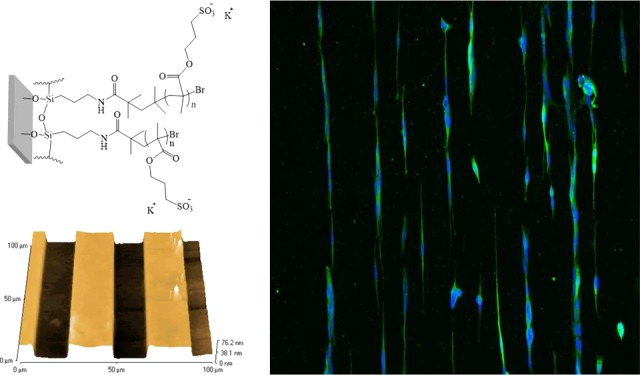
Figure 1.

AFM height profiles showing the patterned PKSPMA polymer brushes on glass containing gaps of (A) 20, (B) 50, (C) 75, and (D) 100 μm channel widths, containing the noncoated glass for cell growth. The PKSPMA brushes are present in the pillars with widths of approximately 20, 40, 80, and 100 μm, respectively.
2.2. Effect of Pattern Size and Cell Density on SH-SY5Y
To examine the response of the SH-SY5Y cells toward the patterned surfaces generated, various channel sizes (20, 50, 75, and 100 μm width) at various cell densities were examined (5000, 10 000, and 15 000 cells/cm2; Figures 2 and 3).
Figure 2.
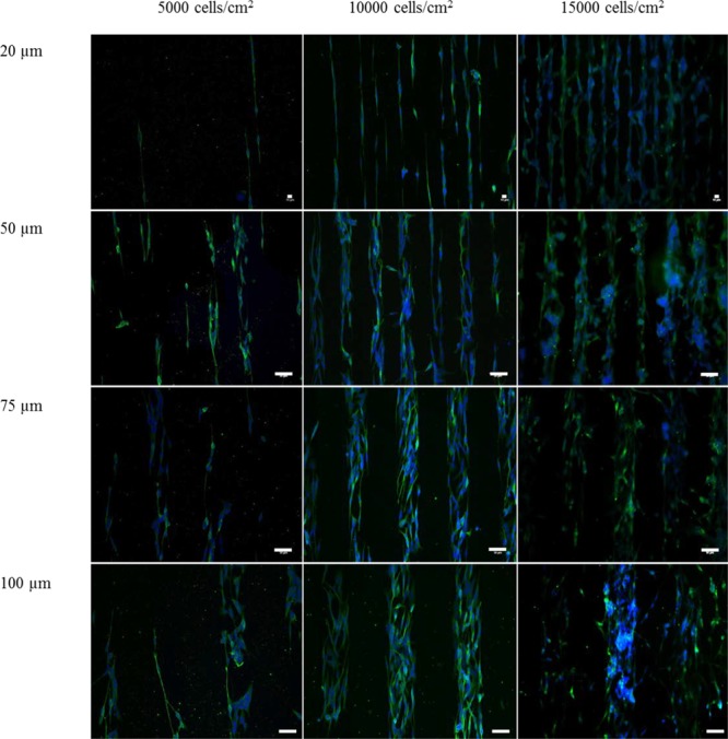
Effect of cell density and channel width on neuronal arrangement for the SH-SY5Y cells. Patterned SH-SY5Y cells seeded at 5000, 10 000, and 15 000 cells/cm2 in 20 μm (top row), 50 μm (upper-medium row), 75 μm (lower-medium row), and 100 μm (bottom row) wide channels. The SH-SY5Y cells were seeded evenly and cultured in growth media (GM) for 3 days. To promote neurite extension, the cells were consequently cultured for 3 days in GM. Green = β tubulin III (microtubules, neuronal cell body), blue = 4′,6-diamidino-2-phenylindole (DAPI; nuclei). Scale bars have been indicated in the image (for 20 μm, scale bar = 10 μm; for 50, 75, and 100 μm wide channels, scale bar = 50 μm).
Figure 3.
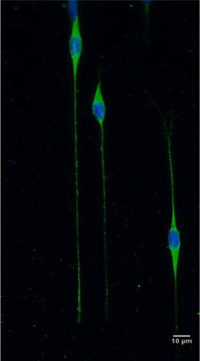
SH-SY5Y cells seeded on the glass/PKSPMA patterns at 10 000 cells/cm2 in 20 μm wide channels. When appropriate channel width and cell density were attained, neurite directionality and long extension were achieved. Green = β tubulin III (microtubules, neuronal cell body), blue = DAPI (nuclei). Scale bar = 10 μm.
The variations in channel width, especially from the widest to the narrowest channels, showed an effect on neurite length, neurite number, and nuclei alignment (see Figure 4A–C). However, the channel width did not affect the cell confinement within the pattern (Figure 4D). Neurite extension was found to be the greatest when the channel size was 20 μm, at which the cells were seen to rearrange their cytoskeleton to fit in the channel, exhibiting an elongated shape and extending neurites.
Figure 4.

Morphological analysis of the SH-SY5Y cell patterns at different cell densities (5000, 10 000, and 15 000 cells/cm2) and channel widths (20, 50, 75, and 100 μm). (A) Average neurite length across the different channel widths and cell densities. (B) Percentage of cells extending the neurites within the channels at different cell densities. (C) Analysis of nuclei alignment within the channel, where perfect alignment was considered at 0°. The nuclei alignment data were normalized to the angle of each channel and analyzed by IQ ranges. (D) Efficiency of PKSPMA patterns in constraining the cells depending on the channel width and the cell density. The number of cells within the channels divided by the total number of cells presented in the image was defined as the percentage of cell confinement. Error bars represent standard deviation (SD) of the mean. Statistical analyses were assessed by two-way analysis of variance (ANOVA) followed by Bonferroni’s post hoc method. Stars indicate the statistical differences between the different channel sizes and cell densities (p < 0.05, n = 4).
A reduction in the neurite length was observed as the channel size increased, perhaps because of an increase in the cells per channel which led to cell–cell communication rather than neurite extension (Figure 4A, p < 0.05 between 20 vs 100 μm for 5000 and 10 000 cells/cm2 and 20 vs 75 μm channel width for 5000 and 15 000 cells/cm2). This was also reflected in the amount of cells generating neurites, where 50, 75, and 100 μm wide channels had fewer cells containing neurites, although this trend was nonsignificant (Figure 4B, p > 0.05). The nuclei were considered perfectly aligned within the pattern when the interquartile (IQ) range value approached 0. The cells were more aligned when the channel size was 20 μm (Figure 4C), where the individual cells extended themselves across the line pattern, showing a certain degree of neurite directionality. Thus, there was a clear trend toward smaller channel sizes, obtaining more aligned cells, when compared to the bigger channel sizes (Figure 4C, p < 0.05 for 20 vs 100 μm channel width for 5000, 10 000, and 15 000 cells/cm2 and 20 vs 75 μm channel width for 5000 cells/cm2). Cell confinement, which was referred to as the efficiency of the pattern to contain the cells within the channels, showed no trends with regard to the different channel sizes. This was a further indication that PKSPMA brushes were effective as a cell-repulsive coating, independent of the shape of the pattern (Figure 4D).
Further analysis was also focused on whether the position of the cell within the pattern would be defined by the amount of cells used, and hence various cell densities were tested for the several channel widths (Figure 4). The cell densities used showed a little difference toward the parameters measured (neurite length, the percentage of cells generating neurites, nuclei alignment, and cell confinement) across the different channel widths. However, some nonsignificant tendencies could be observed when comparing the different cell densities used. There was a greater spreading of neurons and their neurites through the channel width at the lowest cell densities (5000 cells/cm2) and less aligned and spread neurons because of the overcrowding of the channels at the highest cell density (15 000 cells/cm2). Alternatively, the medium cell density (10 000 cells/cm2) seemed more consistent among the different parameters used, resulting in both cell–cell contact and the possibility of neurite spreading. Overall, these results indicated that cell density did not affect significantly the different channel sizes and that the 20 μm channel width showed the constraint of elongated cells and was suitable for obtaining neurite directionality.
3. Discussion
The uncontrolled neuronal growth, as well as the random neurite sprouting in conventional in vitro culture conditions, prevents the design of accurate biomimetic neuronal models.47 Because of the need for obtaining spatial neural organization, micropatterning has been raised as a potential tool for mimicking microenvironments.48−50 With such methodologies, a surface material can be designed to adapt neurons onto various shapes and sizes, resulting in potential advantages for neuronal tissue engineering applications.8,13,14
Many examples of micropatterns published in the literature are based on the use of extracellular matrix proteins, SAMs, or polymer brushes.3,23,48,51,52 This work represents the use of a PKSPMA polymer brush as a synthetic polymer coating which has been shown previously to resist cellular attachment.45,49 By utilizing photolithography, it may be possible in future studies to pattern PKSPMA into more complex geometries, potentially leading to the control of cellular growth in a more developed architecture. Because of the flexibility of the design available when using this approach, various channel widths were utilized in this study to analyze the effect of cell confinement, as geometrical constraints have been known to influence neuronal morphology.23,53 The neurons confined themselves across the channel widths, and neurite extension appeared to be slightly higher when measured in 20 μm channels, whereas lower percentages of neurons were aligned on 75 and 100 μm width channels, respectively. Furthermore, neurites also appeared to be aligned in 20 μm channels. Like chemical coatings, geometrical constraints are also known to influence neuronal morphology.8 In a study performed by Nam et al., the SH-SY5Y cells were seeded on polydimethylsiloxane substrates containing various channel sizes (20, 40, 60, and 100 μm). The study showed that in 20 μm width patterns, only two neurites were observed and that these were confined along the pattern direction. The neurites appeared highly aligned when measured in 20 μm channels, whereas low percentages of neurites were aligned on 100 μm width channels. In addition, the mean neurite length was small in channels 100 μm wide, but as the channel width reduced, the neurite length increased.54 Smaller channel widths were utilized in a study performed by Klein et al. This group showed the patterning of the SH-SY5Y cells by microcontact printing in 5, 8, 10, and 20 μm wide channels. Elongated single cells could be observed in this study for 5, 8, and 10 μm wide channels, whereas double lines of neurons were observed in the 20 μm wide channel.55 This contradicted the study presented by Yang et al., where 20 μm wide lines were shown to give single lines of the SH-SY5Y cells.23 As observed in this current work, the amount of cells seeded could lead either to the free outward spreading of a single line of cells toward the 20 μm channels or to the presence of various cells overlapping across the width of the channel. Yang et al. also used two different cell densities, showing that cell spreading was reduced when the cell density increased. In a work reported by Klein et al., the cell density used was even greater than the cell densities used in this current study (20 000 cells/cm2). The disparity between the studies could be that at high cell densities, multiple cells can position themselves across the channel at the beginning of the culture, meaning that the space to migrate across the channel becomes very limited. Other factors such as the method of seeding, the surface area occupied by the cells, and so forth could influence the results. These results suggest that the constraints in cell shape are greatly affected by geometrical constraints, but other factors such as cell density could influence the neuronal arrangement. Such a control on neuronal guidance could be used to underpin the neurological processes behind the neurodegenerative diseases by the specific study of single neuronal connections down the track, predicated by the ability of the patterned neurons to produce functioning electrical connections.
4. Conclusions
The progress in microfabrication over the years has allowed for a multidisciplinary area where biology, biotechnology, and engineering can work together to assess the challenges in material design and cell biology. Its use in this study allowed for the flexibility in the design, achieving the rearrangement of neuronal cells on different channel sizes and various cell densities, obtaining neurite directionality and elongation. The use of PKSPMA brushes was used as a potential cell-repulsive coating, and its combination with the micropatterning techniques resulted in a system with instructive cues for neuronal guidance, moving away from the homogeneous and simplistic surface presented in conventional models. The use of such patterns could be essential to closely study the neuronal behavior; the micropatterns could be controlled in order such that cell–cell communication, single cell differentiation, or polarization could be monitored. Furthermore, a more complex design can be utilized, obtaining more complex neuronal networks for neurophysiological processes and for neuronal co-cultures to study heterotypical communication.
5. Methods
5.1. Materials
The chemicals (3-aminopropyl)triethoxysilane (APTES, >98%), triethylamine (TEA, >99.5%), 2-bromoisobutyryl bromide (BIBB, >98%), copper(I) bromide (CuBr, 99.9%), copper(II) bromide (CuBr2, 98%), 2,2′-bipyridyl (99%), and 3-sulfopropyl methacrylate potassium salt (KSPMA, 98%) were purchased from Sigma-Aldrich (Welwyn Garden City, Hertfordshire, UK) and used as received. Glass slides (1.0–1.2 mm thick in dimensions of 25.4 × 76.2 mm) were purchased from Scientific Glass Laboratories Ltd. (Canal lane, Tunstall, Stoke-on Trent, UK), and silicon wafers (⟨100⟩ orientation, boron-doped, 0–100 Ω cm, ∼500 μm thickness) were purchased from Compart Technology (Peterborough, Cambridgeshire, UK).
For cell culture experiments, Dulbecco’s modified Eagle medium (DMEM) GlutaMAX, heat-inactivated fetal bovine serum (FBS), and penicillin/streptomycin (Pen–Strep: 10 000 units penicillin and 10 mg streptomycin/mL, P/S) were purchased from Gibco (Invitrogen). Primary antibody monoclonal anti-β tubulin III produced in mouse (∼2.0 mg/mL) and all-trans retinoic acid (ATRA) were acquired from Sigma-Aldrich. DAPI nuclei counterstain and Alexa Fluor 488 goat antimouse IgG were obtained from Life Technologies (Thermo Scientific).
5.2. Methods
5.2.1. Formation of PKSPMA Brushes by Surface-Initiated Atom Transfer Radical Polymerization
The cleaning, aminosylation, initiator deposition, and brush attachment have been described elsewhere.45,46 Briefly, the wafers and glass slides were cleaned with a UV/O3 photoreactor (PR-100, UVP). The cleaned samples were then placed into a vacuum oven (Thermo Scientific, Heraeus) with approximately 10 drops of APTES in an aluminum foil tray alongside, and the oven was sealed for 30 min at 25 °C and <50 mbar. The samples were sequentially annealed in an oven for 30 min at 110 °C. For the attachment of the BIBB initiator, the APTES-functionalized samples were placed in tubes under N2 atmosphere, and dry tetrahydrofuran (THF, 10 mL), dry TEA (0.3 mL, 2.1 mmol), and BIBB (0.26 mL, 2.10 mmol) were added and maintained in a static environment for an hour. The samples were taken out and rinsed with THF, methanol, and distilled water to remove any solid triethylammonium bromide which had formed on the substrates. For the brush attachment, the KSPMA monomer (17.29 g, 70.2 mmol), methanol (20 mL), and distilled water (10 mL) were stirred and degassed by bubbling through N2 for 20 min in a sealed 100 mL three-neck round-bottom flask. After the complete dissolution of the monomer, 2,2′-bipyridyne (0.651 g, 4.17 mmol) along with copper(II) bromide (0.0179 g, 0.08 mmol) was added. The mixture was stirred and degassed for an hour, and then copper(I) bromide (0.230 g, 1.6 mmol) was added. The monomer solution was then transferred into tubes containing the initiator-coated samples at N2 atmosphere for 24 h. After the polymerization was complete, the samples were washed sequentially with methanol and distilled water and dried under N2 (Figure 5).
Figure 5.

Structural formula of the PKSPMA polymer brush bound to a functionalized glass surface.
5.2.2. Photolithography Process
The glass/PKSPMA samples were patterned using photolithography, as described in Figure 6. An S1813 photoresist (MicroChem, Chestech Ltd., Warwickshire) was spin-coated (Laurell WS-650-23B) onto solvent-washed glass slides at 3000 rpm for 1 min (Figure 6a). Lithography was carried out on a Cannon PLA500 mask aligner with a chrome/glass mask. The spin-coated samples were soft-baked at 115 °C on a hot plate (Figure 6b) and UV exposed under an i-line (365 nm) with a power at ∼120 mJ/cm2 (Figure 6c), before developing the samples using a Microposit developer (1:1 v/v with distilled water). The developed samples were then hard-baked at 180–200 °C for ∼15 min and left to slowly cool down until room temperature (Figure 6d). The areas where the photoresist was no longer present were used to grow PKSPMA brushes by attaching the APTES–BIBB initiator (Figure 6e,f) followed by the attachment of the PKSPMA brushes (Figure 6g). Once the PKSPMA brushes were attached, the remnant photoresist was removed by incubating the sample in dimethyl sulfoxide (DMSO) (Figure 6h). The resultant patterns consisted of parallel PKSPMA lines with different channel widths (20, 40, 80, and 100 μm) and gaps (20, 50, 75, and 100 μm width) containing the noncoated areas. The pattern was confirmed under a Bruker Explorer AFM using the SPMLab software in a tapping mode with a high resonance frequency silicon probe.
Figure 6.

Schematic of the photolithographic process used to obtain PKSPMA/glass patterns. Plain glass slides were (a) spin-coated with the photoresist S1813, (b) soft-baked, and (c) exposed under UV light through a mask containing the channel geometries. Thereafter, the samples were developed and hard-baked (d) obtaining the exposed areas of the noncoated glass for the attachment of APTES, BIBB, and PKSPMA (e–g). The remaining photoresist covering the nonexposed areas with the noncoated glass was washed off with DMSO (h), obtaining stripes of PKSPMA and noncoated glass.
5.2.3. SH-SY5Y Neuronal Cell Culture
The SH-SY5Y neuroblastoma cell line (European collection of cell cultures) was cultured under GM conditions consisting of DMEM GlutaMAX supplemented with 10% v/v heat-inactivated FBS and 1% v/v P/S. The cells were incubated in a humid environment of 5% CO2 atmosphere at 37 °C until a 80% confluency was reached. The cells were treated with the trypsin enzyme for detachment, counted, and plated evenly onto the patterned samples at various cell densities (5000, 10 000, and 15 000 cells/cm2). These samples were cultured in GM for a period of 3 days, and thereafter neuronal differentiation was induced by incubating the cells in differentiation media, consisting of DMEM GlutaMAX, 10% heat-inactivated FBS, 1% P/S, and 10 μM of ATRA-differentiating agent, for another 3 days. The patterned samples were then fixed and used for immunocytochemistry. Prior to experimentation, the patterned samples were sterilized by incubation in 70% ethanol for at least an hour and then left to dry under sterile conditions in a biological safety cabinet.
5.2.4. Immunocytochemistry
The cells were fixed with 3.7% paraformaldehyde (Sigma-Aldrich) in phosphate-buffered saline and subsequently blocked and permeabilized with 5% goat serum (GS) and 0.2% Triton-X100 in 1× tris-buffered saline (1× TBS) for 30 min at room temperature. Thereafter, a solution with monoclonal mouse anti-β-tubulin III antibody (1:200 v/v) and 2% GS in TBS was added and incubated for 2 h. This solution was removed, and Alexa Fluor 488-conjugated goat antimouse IgG (1:200 v/v) was added along with nuclear counterstain DAPI (1:1000 v/v), containing 2% GS and 0.2% Triton-X100 in TBS. The solution was incubated in the dark for an hour, and thereafter the samples were rinsed with 1× TBS and mounted onto cover slides using the Fluoromount Aqueous Mounting Medium.
5.2.5. Image and Statistical Analysis
The fluorescence microscope images were taken using a LEICA DM2500 microscope with a 20× magnification objective. Five random images were taken at the end of the experiment for every sample at every channel size. The nuclei alignment, percentage of cells generating neurites, neurite length, and cell confinement were analyzed for the various channel sizes.
The nuclei alignment was obtained from DAPI images using a customized Fiji macro (Java 1.6.0_24) image analysis software (Figure S1). The angle of the nuclei was obtained by using the channels as the reference point. Consequently, the vertical lines parallel to the channels were considered as the points where the cells were perfectly aligned (0°). The nuclei alignment data were normalized to the angle of each channel and analyzed by IQ ranges. An IQ range is defined as the difference in alignment between the 25th and 75th percentile of measured values. The measures were considered when at least three cells were in the image.
To calculate the percentage of cells generating neurites and cell confinement, a cell counter plugin in the Fiji software was used. The number of cells generating neurites divided by the total number of cells counted was defined as the percentage of cells generating neurites. Likewise, the number of cells within the channels divided by the total number of cells presented in the image was defined as the percentage of cell confinement. The neurite extension was traced with “freehand” segmented lines and measured with the Fiji image analysis software (Figure S2). The neuron protrusions were considered neurites when these were the same or greater than 10 μm. All the data are presented as mean (±SD). A two-way ANOVA was used to analyze the channel data followed by Bonferroni’s post hoc method to determine the interrelation of the channels sizes over the different cell densities. The differences were considered statistically significant for p ≤ 0.05.
Acknowledgments
We thank Loughborough University for financially supporting this project, the miniCDT prosthetic group, and also EPSRC EP/L02067X/1.
Supporting Information Available
The Supporting Information is available free of charge on the ACS Publications website at DOI: 10.1021/acsomega.8b01698.
Illustration of the analysis of nuclei alignment with Fiji macro plugin and neurite length, macroscopic observation of the color changes on Si wafer before and after PKSPMA deposition, and the further effect of PKSPMA on different geometries (PDF)
The authors declare no competing financial interest.
Supplementary Material
References
- Rajnicek A.; Britland S.; McCaig C. Contact Guidance of CNS Neurites on Grooved Quartz: Influence of Groove Dimensions, Neuronal Age and Cell Type. J. Cell Sci. 1997, 110, 2905–2913. [DOI] [PubMed] [Google Scholar]
- Silver J.; Sidman R. L. A Mechanism for the Guidance and Topographic Patterning of Retinal Ganglion Cell Axons. J. Comp. Neurol. 1980, 189, 101–111. 10.1002/cne.901890106. [DOI] [PubMed] [Google Scholar]
- Clark P.; Britland S.; Connolly P. Growth Cone Guidance and Neuron Morphology on Micropatterned Laminin Surfaces. J. Cell Sci. 1993, 105, 203–212. [DOI] [PubMed] [Google Scholar]
- Nguyen Q. T.; Sanes J. R.; Lichtman J. W. Pre-Existing Pathways Promote Precise Projection Patterns. Nat. Neurosci. 2002, 5, 861–867. 10.1038/nn905. [DOI] [PubMed] [Google Scholar]
- Shah S.; Solanki A.; Lee K.-B. Nanotechnology-Based Approaches for Guiding Neural Regeneration. Acc. Chem. Res. 2016, 49, 17–26. 10.1021/acs.accounts.5b00345. [DOI] [PMC free article] [PubMed] [Google Scholar]
- Dowell-Mesfin N. M.; Abdul-Karim M.-A.; Turner A. M. P.; Schanz S.; Craighead H. G.; Roysam B.; Turner J. N.; Shain W. Topographically Modified Surfaces Affect Orientation and Growth of Hippocampal Neurons. J. Neural. Eng. 2004, 1, 78–90. 10.1088/1741-2560/1/2/003. [DOI] [PubMed] [Google Scholar]
- Ruardij T. G.; Goedbloed M. H.; Rutten W. L. C. Adhesion and Patterning of Cortical Neurons on Polyethylenimine- and Fluorocarbon-Coated Surfaces. IEEE Trans. Biomed. Eng. 2000, 47, 1593–1599. 10.1109/10.887940. [DOI] [PubMed] [Google Scholar]
- Khan S.; Newaz G. A Comprehensive Review of Surface Modification for Neural Cell Adhesion and Patterning. J. Biomed. Mater. Res., Part A 2010, 93A, 1209–1224. 10.1002/jbm.a.32698. [DOI] [PubMed] [Google Scholar]
- Falconnet D.; Csucs G.; Michelle Grandin H.; Textor M. Surface Engineering Approaches to Micropattern Surfaces for Cell-Based Assays. Biomaterials 2006, 27, 3044–3063. 10.1016/j.biomaterials.2005.12.024. [DOI] [PubMed] [Google Scholar]
- Moroni L.; Klein Gunnewiek M.; Benetti E. M. Polymer Brush Coatings Regulating Cell Behavior: Passive Interfaces Turn into Active. Acta Biomater. 2014, 10, 2367–2378. 10.1016/j.actbio.2014.02.048. [DOI] [PubMed] [Google Scholar]
- Rühe J.; Yano R.; Lee J.-S.; Köberle P.; Knoll W.; Offenhäusser A. Tailoring of Surfaces with Ultrathin Polymer Films for Survival and Growth of Neurons in Culture. J. Biomater. Sci., Polym. Ed. 1999, 10, 859–874. 10.1163/156856299x00928. [DOI] [PubMed] [Google Scholar]
- Gomez N.; Chen S.; Schmidt C. E. Polarization of Hippocampal Neurons with Competitive Surface Stimuli: Contact Guidance Cues Are Preferred over Chemical Ligands. J. R. Soc. Interface 2007, 4, 223–233. 10.1098/rsif.2006.0171. [DOI] [PMC free article] [PubMed] [Google Scholar]
- Lee J. W.; Lee K. S.; Cho N.; Ju B. K.; Lee K. B.; Lee S. H. Topographical Guidance of Mouse Neuronal Cell on SiO2 Microtracks. Sens. Actuators, B 2007, 128, 252–257. 10.1016/j.snb.2007.06.017. [DOI] [Google Scholar]
- Poudel I.; Lee J. S.; Tan L.; Lim J. Y. Micropatterning-Retinoic Acid Co-Control of Neuronal Cell Morphology and Neurite Outgrowth. Acta Biomater. 2013, 9, 4592–4598. 10.1016/j.actbio.2012.08.039. [DOI] [PubMed] [Google Scholar]
- Kane R.; Takayama S.; Ostuni E.; Ingber D. E.; Whitesides G. M. Patterning Proteins and Cells Using Soft Lithography. Biomaterials 1999, 20, 2363–2376. 10.1016/s0142-9612(99)00165-9. [DOI] [PubMed] [Google Scholar]
- Takahashi H.; Nakayama M.; Itoga K.; Yamato M.; Okano T. Micropatterned Thermoresponsive Polymer Brush Surfaces for Fabricating Cell Sheets with Well-Controlled Orientational Structures. Biomacromolecules 2011, 12, 1414–1418. 10.1021/bm2000956. [DOI] [PubMed] [Google Scholar]
- Molnar P.; Wang W.; Natarajan A.; Rumsey J. W.; Hickman J. J. Photolithographic Patterning of C2C12 Myotubes Using Vitronectin as Growth Substrate in Serum-Free Medium. Biotechnol. Prog. 2007, 23, 265–268. 10.1021/bp060302q. [DOI] [PMC free article] [PubMed] [Google Scholar]
- Zhou Z.; Yu P.; Geller H. M.; Ober C. K. Biomimetic Polymer Brushes Containing Tethered Acetylcholine Analogs for Protein and Hippocampal Neuronal Cell Patterning. Biomacromolecules 2013, 14, 529–537. 10.1021/bm301785b. [DOI] [PMC free article] [PubMed] [Google Scholar]
- Mahoney M. J.; Chen R. R.; Tan J.; Mark Saltzman W. The Influence of Microchannels on Neurite Growth and Architecture. Biomaterials 2005, 26, 771–778. 10.1016/j.biomaterials.2004.03.015. [DOI] [PubMed] [Google Scholar]
- Metavarayuth K.; Sitasuwan P.; Zhao X.; Lin Y.; Wang Q. Influence of Surface Topographical Cues on the Differentiation of Mesenchymal Stem Cells in Vitro. ACS Biomater. Sci. Eng. 2016, 2, 142–151. 10.1021/acsbiomaterials.5b00377. [DOI] [PubMed] [Google Scholar]
- Yang F.; Murugan R.; Wang S.; Ramakrishna S. Electrospinning of Nano/micro Scale Poly(l-Lactic Acid) Aligned Fibers and Their Potential in Neural Tissue Engineering. Biomaterials 2005, 26, 2603–2610. 10.1016/j.biomaterials.2004.06.051. [DOI] [PubMed] [Google Scholar]
- Roach P.; Parker T.; Gadegaard N.; Alexander M. R. Surface Strategies for Control of Neuronal Cell Adhesion: A Review. Surf. Sci. Rep. 2010, 65, 145–173. 10.1016/j.surfrep.2010.07.001. [DOI] [Google Scholar]
- Yang I. H.; Co C. C.; Ho C.-C. Alteration of Human Neuroblastoma Cell Morphology and Neurite Extension with Micropatterns. Biomaterials 2005, 26, 6599–6609. 10.1016/j.biomaterials.2005.04.024. [DOI] [PubMed] [Google Scholar]
- Corey J. M.; Gertz C. C.; Sutton T. J.; Chen Q.; Mycek K. B.; Wang B.-S.; Martin A.; Johnson S. L.; Feldman E. L. Patterning N-Type and S-Type Neuroblastoma Cells with Pluronic F108 and ECM Proteins. J. Biomed. Mater. Res., Part A 2010, 93, 673–686. 10.1002/jbm.a.32485. [DOI] [PMC free article] [PubMed] [Google Scholar]
- Cheng J.; Zhu G.; Wu L.; Du X.; Zhang H.; Wolfrum B.; Jin Q.; Zhao J.; Offenhäusser A.; Xu Y. Photopatterning of Self-Assembled Poly (Ethylene) Glycol Monolayer for Neuronal Network Fabrication. J. Neurosci. Methods 2013, 213, 196–203. 10.1016/j.jneumeth.2012.12.020. [DOI] [PubMed] [Google Scholar]
- Santoro F.; Panaitov G.; Offenhäusser A. Defined Patterns of Neuronal Networks on 3d Thiol-Functionalized Microstructures. Nano Lett. 2014, 14, 6906–6909. 10.1021/nl502922b. [DOI] [PubMed] [Google Scholar]
- Palyvoda O.; Bordenyuk A. N.; Yatawara A. K.; McCullen E.; Chen C.-C.; Benderskii A. V.; Auner G. W. Molecular Organization in SAMs Used for Neuronal Cell Growth. Langmuir 2008, 24, 4097–4106. 10.1021/la7032675. [DOI] [PubMed] [Google Scholar]
- Olivier A.; Meyer F.; Raquez J.-M.; Damman P.; Dubois P. Surface-Initiated Controlled Polymerization as a Convenient Method for Designing Functional Polymer Brushes: From Self-Assembled Monolayers to Patterned Surfaces. Prog. Polym. Sci. 2012, 37, 157–181. 10.1016/j.progpolymsci.2011.06.002. [DOI] [Google Scholar]
- Jans K.; Van Meerbergen B.; Reekmans G.; Bonroy K.; Annaert W.; Maes G.; Engelborghs Y.; Borghs G.; Bartic C. Chemical and Biological Characterization of Thiol SAMs for Neuronal Cell Attachment. Langmuir 2009, 25, 4564–4570. 10.1021/la802217r. [DOI] [PubMed] [Google Scholar]
- Senaratne W.; Andruzzi L.; Ober C. K. Self-Assembled Monolayers and Polymer Brushes in Biotechnology: Current Applications and Future Perspectives. Biomacromolecules 2005, 6, 2427–2448. 10.1021/bm050180a. [DOI] [PubMed] [Google Scholar]
- Raynor J. E.; Capadona J. R.; Collard D. M.; Petrie T. A.; García A. J. Polymer Brushes and Self-Assembled Monolayers: Versatile Platforms to Control Cell Adhesion to Biomaterials (Review). Biointerphases 2009, 4, FA3–FA16. 10.1116/1.3089252. [DOI] [PubMed] [Google Scholar]
- Pernites R. B.; Foster E. L.; Felipe M. J. L.; Robinson M.; Advincula R. C. Patterned Surfaces Combining Polymer Brushes and Conducting Polymer via Colloidal Template Electropolymerization. Adv. Mater. 2011, 23, 1287–1292. 10.1002/adma.201004003. [DOI] [PubMed] [Google Scholar]
- Edmondson S.; Osborne V. L.; Huck W. T. S. Polymer Brushes via Surface-Initiated Polymerizations. Chem. Soc. Rev. 2004, 33, 14–22. 10.1039/b210143m. [DOI] [PubMed] [Google Scholar]
- Rubio N.; Au H.; Leese H. S.; Hu S.; Clancy A. J.; Shaffer M. S. P. Grafting from versus Grafting to Approaches for the Functionalization of Graphene Nanoplatelets with Poly(methyl Methacrylate). Macromolecules 2017, 50, 7070–7079. 10.1021/acs.macromol.7b01047. [DOI] [Google Scholar]
- Minko S.; Patil S.; Datsyuk V.; Simon F.; Eichhorn K.-J.; Motornov M.; Usov D.; Tokarev I.; Stamm M. Synthesis of Adaptive Polymer Brushes via “Grafting To” Approach from Melt. Langmuir 2002, 18, 289–296. 10.1021/la015637q. [DOI] [Google Scholar]
- Brittain W. J.; Minko S. A Structural Definition of Polymer Brushes. J. Polym. Sci., Part A: Polym. Chem. 2007, 45, 3505–3512. 10.1002/pola.22180. [DOI] [Google Scholar]
- Wischerhoff E.; Uhlig K.; Lankenau A.; Börner H. G.; Laschewsky A.; Duschl C.; Lutz J.-F. Controlled Cell Adhesion on PEG-Based Switchable Surfaces. Angew. Chem., Int. Ed. 2008, 47, 5666–5668. 10.1002/anie.200801202. [DOI] [PubMed] [Google Scholar]
- Zhu B.; Eurell T.; Gunawan R.; Leckband D. Chain-Length Dependence of the Protein and Cell Resistance of Oligo(ethylene Glycol)-Terminated Self-Assembled Monolayers on Gold. J. Biomed. Mater. Res. 2001, 56, 406–416. . [DOI] [PubMed] [Google Scholar]
- Dong R.; Molloy R. P.; Lindau M.; Ober C. K. Direct Synthesis of Quaternized Polymer Brushes and Their Application for Guiding Neuronal Growth. Biomacromolecules 2010, 11, 2027–2032. 10.1021/bm1003702. [DOI] [PubMed] [Google Scholar]
- Blakeston A. C.; Alswieleh A. M.; Heath G. R.; Roth J. S.; Bao P.; Cheng N.; Armes S. P.; Leggett G. J.; Bushby R. J.; Evans S. D. New Poly(amino Acid Methacrylate) Brush Supports the Formation of Well-Defined Lipid Membranes. Langmuir 2015, 31, 3668–3677. 10.1021/la504163s. [DOI] [PMC free article] [PubMed] [Google Scholar]
- Yang H.; Chen Y.; Liu Y.; Nie L.; Yao S. One-Pot Synthesis of (3-Sulfopropyl Methacrylate Potassium)-Silica Hybrid Monolith via Thiol-Ene Click Chemistry for CEC. Electrophoresis 2013, 34, 510–517. 10.1002/elps.201200354. [DOI] [PubMed] [Google Scholar]
- Xu Y.; Walther A.; Müller A. H. E. Direct Synthesis of Poly(potassium 3-sulfopropyl methacrylate) Cylindrical Polymer Brushes via ATRP Using a Supramolecular Complex With Crown Ether. Macromol. Rapid Commun. 2010, 31, 1462–1466. 10.1002/marc.201000157. [DOI] [PubMed] [Google Scholar]
- Wan F.; Pei X.; Yu B.; Ye Q.; Zhou F.; Xue Q. Grafting Polymer Brushes on Biomimetic Structural Surfaces for Anti-Algae Fouling and Foul Release. ACS Appl. Mater. Interfaces 2012, 4, 4557–4565. 10.1021/am300912w. [DOI] [PubMed] [Google Scholar]
- Zhou Z.; Yu P.; Geller H. M.; Ober C. K. The Role of Hydrogels with Tethered Acetylcholine Functionality on the Adhesion and Viability of Hippocampal Neurons and Glial Cells. Biomaterials 2012, 33, 2473–2481. 10.1016/j.biomaterials.2011.12.005. [DOI] [PMC free article] [PubMed] [Google Scholar]
- Pardo-Figuerez M.; Martin N. R. W.; Player D. J.; Capel A. J.; Christie S. D. R.; Lewis M. P. Neural and Aneural Regions Generated by the Use of Chemical Surface Coatings. ACS Biomater. Sci. Eng. 2018, 4, 98–106. 10.1021/acsbiomaterials.7b00663. [DOI] [PubMed] [Google Scholar]
- Ramstedt M.; Cheng N.; Azzaroni O.; Mossialos D.; Mathieu H. J.; Huck W. T. S. Synthesis and Characterization of poly(3-Sulfopropylmethacrylate) Brushes for Potential Antibacterial Applications. Langmuir 2007, 23, 3314–3321. 10.1021/la062670+. [DOI] [PubMed] [Google Scholar]
- Yamamoto H.; Demura T.; Morita M.; Banker G. A.; Tanii T.; Nakamura S. Differential Neurite Outgrowth Is Required for Axon Specification by Cultured Hippocampal Neurons. J. Neurochem. 2012, 123, 904–910. 10.1111/jnc.12001. [DOI] [PMC free article] [PubMed] [Google Scholar]
- Gautrot J. E.; Trappmann B.; Oceguera-Yanez F.; Connelly J.; He X.; Watt F. M.; Huck W. T. S. Exploiting the Superior Protein Resistance of Polymer Brushes to Control Single Cell Adhesion and Polarisation at the Micron Scale. Biomaterials 2010, 31, 5030–5041. 10.1016/j.biomaterials.2010.02.066. [DOI] [PMC free article] [PubMed] [Google Scholar]
- Tan K. Y.; Lin H.; Ramstedt M.; Watt F. M.; Huck W. T. S.; Gautrot J. E. Decoupling Geometrical and Chemical Cues Directing Epidermal Stem Cell Fate on Polymer Brush-Based Cell Micro-Patterns. Integr. Biol. 2013, 5, 899–910. 10.1039/c3ib40026c. [DOI] [PubMed] [Google Scholar]
- Hong D.; Bae K. E.; Yoo S.; Kang K.; Jang B.; Kim J.; Kim S.; Jeon S.; Nam Y.; Kim Y.-G.; et al. Generation of Cellular Micropatterns on a Single-Layered Graphene Film. Macromol. Biosci. 2014, 14, 314–319. 10.1002/mabi.201300346. [DOI] [PubMed] [Google Scholar]
- Chelli B.; Barbalinardo M.; Valle F.; Greco P.; Bystrenova E.; Bianchi M.; Biscarini F. Neural Cell Alignment by Patterning Gradients of the Extracellular Matrix Protein Laminin. Interface Focus 2014, 4, 20130041. 10.1098/rsfs.2013.0041. [DOI] [PMC free article] [PubMed] [Google Scholar]
- Koh H. S.; Yong T.; Chan C. K.; Ramakrishna S. Enhancement of Neurite Outgrowth Using Nano-Structured Scaffolds Coupled with Laminin. Biomaterials 2008, 29, 3574–3582. 10.1016/j.biomaterials.2008.05.014. [DOI] [PubMed] [Google Scholar]
- Junkin M.; Wong P. K. Probing Cell Migration in Confined Environments by Plasma Lithography. Biomaterials 2011, 32, 1848–1855. 10.1016/j.biomaterials.2010.11.009. [DOI] [PMC free article] [PubMed] [Google Scholar]
- Nam K. H.; Jamilpour N.; Mfoumou E.; Wang F. Y.; Zhang D. D.; Wong P. K. Probing Mechanoregulation of Neuronal Differentiation by Plasma Lithography Patterned Elastomeric Substrates. Sci. Rep. 2014, 4, 6965. 10.1038/srep06965. [DOI] [PMC free article] [PubMed] [Google Scholar]
- Klein C. L.; Scholl M.; Maelicke A. Neuronal Networks in Vitro: Formation and Organization on Biofunctionalized Surfaces. J. Mater. Sci. Mater. Med. 1999, 10, 721–727. 10.1023/a:1008975105243. [DOI] [PubMed] [Google Scholar]
Associated Data
This section collects any data citations, data availability statements, or supplementary materials included in this article.