Abstract
For safety reasons, commercial neural implants use charge-balanced biphasic pulses to interact with target neurons using metal electrodes. Short biphasic pulses are used to avoid irreversible electrochemical reactions at the electrode-tissue interfaces. Biphasic pulses are effective at exciting neurons, but quite limited in inhibiting their activity. In contrast, direct current can both excite and inhibit neurons, however delivered to metal electrodes, it causes toxic electrochemical reactions. We recently introduced Safe Direct Current Stimulator (SDCS) technology, which can excite or inhibit neurons without violating the safety criteria. Instead of direct current, SDCS generates an ionic direct current (iDC) from a biphasic input signal using a network of fluidic channels and mechanical valves. A key enabler towards transforming SDCS concept from a benchtop design to an implantable neural prosthesis is the design of a miniature valve. In this work, we present poly-dimethylsiloxane (PDMS) based elastomeric valves, squeeze valve (SV) and plunger valve (PV) capable of being actuated using a shape memory alloy wire.
Keywords: neural inhibition, ionic direct current, shape memory alloy, microfluidic valve, PDMS
I. Introduction
Excitation of neurons using implantable neural prostheses is of great interest to the medical community for effective treatment of several neurological disorders[1][2]. For long-term safety these implants use charged balanced biphasic waveforms delivered to metal electrodes implanted near the neural tissue. Charge balanced biphasic current pulses rather than direct current are used to eliminate irreversible electrochemical reactions by limiting the metal electrodes operation to function within their safe charge injection limits. This technique is effective at exciting neurons but inhibition of neural tissue is difficult to achieve. Inhibition of neural activity is also desired for some therapies and a prosthesis capable of performing excitation as well as inhibition can significantly broaden the clinical impact of these devices. High frequency nerve block can be effective, but it is associated with a number of challenges including a strong onset response and lack of selectivity [4]. Direct current delivered to the neural tissue can excite or inhibit neurons depending on the amplitude and the direction of current flow. However, passing DC at the metal electrode violates the safe charge injection threshold[3] and thus prolonged effects of passing DC through any metallic electrodes are damaging to the surrounding tissue owing to electrolysis and surface corrosion.
We recently introduced a technology, Safe Direct Current Stimulator (SDCS) that has a potential to augment the functionalities of commercially available neural prostheses by enabling long-term neural inhibition or excitation using ionic direct current (iDC)[5]. Conceptually, the SDCS system uses charged balanced square AC waveform as the input signal to the metal electrodes embedded within the device and converts it to a constant iDC via a rectifying mechanism embedded in a fluid channel network. In contrast to applying DC stimulus to metal electrodes directly, this method can comply with the safe charge injection criterion enabling the possibility of chronic neural inhibition or excitation with iDC.
Current rectification of a charged balanced AC signal from an implanted metallic electrode to an iDC represents a substantial technological challenge. To address this challenge, we recently established a proof-of-concept SDCS benchtop prototype consisting of a tubing network that conducts ionic current, with the impedance of the current paths controlled with mechanical valves[6]. Each valve acted as an ionic gate switch, prohibiting the flow of ions when closed and allowing the ion migration when open. These valves when actuated in phase with the input AC pulse stimulus at the metal electrodes within the structure resulted in a reliable iDC delivered to the target tissue. Going forward, successful realization of our SDCS technology as a neural prosthesis is strongly contingent upon the power consumption and the footprint of the desired implant. With the goal of transforming the current benchtop SDCS prototype to implantable device, a substantial innovation in valve design is needed.
Out of several possibilities of valve actuation mechanisms, we selected shape memory alloys as ideal candidates considering their current based reversible actuations. Specifically, nitinol muscle wire exhibits a remarkable shape memory property by contracting its length by approximately 4% under the application of electrical current, while returning to its original shape after withdrawal of the driving current. If the current passed through the wire is under a threshold value provided by the manufacturer, the wire can withstand millions of repeated stress cycles. At optimal actuation conditions of driving current, 50μm diameter nitinol wire generates a maximum pull force of 36 grams. Although the pull forces can be increased by passing more current, the wire suffers from irreversible shape changes due to excessive thermally induced stresses, limiting its long-term use.
The impedance requirements for the microfluidic valve imposed by the SDCS system design stem from the necessity to maintain a maximum safe 30V compliance voltage within the device but still can deliver up to 200uA of output current. This results in a maximum impedance of 150 kΩ that must be distributed among two valves and the tissue interface positioned in a series in the SDCS design. Assuming the impedance of 80kΩ as the upper limit for the device output-tissue interface, we imposed an upper limit of 35kΩ for the open valve state and a minimum 10× increase in impedance from the open to closed state to ensure efficient device operation [5].
In this work, we compare the designs of four miniature fluidic valves made from an elastomeric material, poly-dimethylsiloxane (PDMS), capable of a being actuated with a nitinol muscle wire. To satisfy the pull force criterion, geometry and material of the valve plays an important role in determining the force needed for a complete an effective valve closure. Our motivation for this work comes from a previously published valve design [7], abbreviated as squeeze valve (SV) in this paper. We examine two implementations of this valve, one with a 0.5mm diameter (SV0.5) and the other with a 1.5mm diameter (SV1.5) lumen. We further modified this design into a multilayer plunger valve (PV0.75 and PV0.85). Here we test the feasibility of using these four valve types for SDCS technology.
II. VALVE DESIGN
Two valve designs, named squeeze valve (SV) and plunger valve (PV) presented in this paper, fall in the general category of membrane valves. Each valve has a thin layer of flexible membrane that is deformed under the action of the pull force generated from nitinol muscle wire. When the membrane is sufficiently deflected, it physically blocks the adjacent fluidic channel, thereby increasing the overall ionic impedance. There are key structural differences between SV and PV valves. Firstly, the SV valve has a single layer of fluidic channel underneath its thin elastic membrane, whereas, the PV valve has two fluidic channels stacked on top of each other, connected via a vertical through hole. Secondly, the plunger valve is designed to include an additional structural element, called plunger, which is a small block of PDMS attached to the thin elastic membrane. The mechanism by which that pull force is translated in the valve closure is slightly different for both designs. In case of a closed SV valve, entire fluidic channel is squeezed by the deformed membrane thereby blocking the ionic flow. On the other hand, the vertical through hole is blocked by the downward motion of the plunger in closed PV valve. Fig 1 shows schematic representations of cross-section of each type of valve. Other critical structural details such as fluidic channels, the plunger, the placement of nitinol wire etc. are also highlighted and labeled in the same figure. Fig 1 left column shows the conformational changes in the cross-sections when these valves are switched to a closed state. For effective operation of the PV valves, the nitinol wire is looped over a resin button bonded to the thin membrane.
Fig. 1.
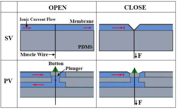
(top) Schematic of the open and closed states of a squeeze valve (SV). (bottom) Schematic of the open and closed states of a plunger valve (PV).
For an SV valve the change of the cross-sectional area is governed by the overall bending characteristics of the thin membrane and in turn a strong function of the channel depth. Hence, a valve with shallower channel will need a small trigger force for its complete closure than a valve constructed with a deeper channel. To test this hypothesis, we designed and tested two squeeze valves, each with a different channel depth, while keeping the membrane layer thickness constant at 0.1 mm. The valves are denoted as SV0.5 and SV1.5 where subscript denotes channel depth of 0.5 mm and 1.5 mm respectively. The fluidic channels were half rounded for effective valve closure compared to a rectangular cross-section.
Unlike the SV valve, the bending of the membrane is translated to the downward motion of the attached plunger in case of PV valves. Even if membrane does not block the entire fluidic channel, the plunger effectively blocked the vertical through hole, thereby decreasing making this design very sensitive to the applied external force. We hypothesize that, this modified valve structure will require lesser closure force than the SV valves and is strongly dependent on the height of the plunger. We constructed and tested two PV valves, PV0.75 and PV0.85 where the subscript denotes plunger height of 0.75 mm and 0.85 mm respectively. The membrane layer thickness and fluidic channel layer depth were held constant at 0.1 mm and 1 mm respectively. The connecting vertical cylindrical through hole was 1.6 mm in diameter and 0.75 mm in height. The fluidic channel dimensions were chosen empirically to satisfy the criterion of open channel impedance of <35kΩ.
For a perfectly closed valve, the impedance measured across the valve should be infinite in theory. For this study, we choose an increase of 10-fold from the open valve impedance value as the criterion representing a closed valve state. The feasibility test for SDCS was conducted by measuring the closure force required to close the valve and valve impedances for all four valve designs as the valve is being closed.
III. Valve Fabrication
The valves were fabricated by inverse replica molding of poly-dimethylsiloxane (PDMS). The squeeze valve was constructed by bonding two separately molded layers of PDMS, namely fluidic channel layer and the thin membrane. On the other hand, the plunger valve consisted of a total of four layers: 2 fluidic channel layers, an intermediate layer for the vertical through hole connecting the two channels and a membrane layer with a plunger. The molds for each layer were created using a 3D printer (B9Creations, South Dakota) which used a photo curable polymer resin (B9R-2 Black Resin, B9Creations, South Dakota). The printed molds were rinsed with distilled water to removed uncured polymer traces. The masters then were post cured using a UV lamp for 12 hours. For an easy peeling-off of cured PDMS blocks, the molds were first treated with a corona treater (BD-20AC, Electro-Technic Products) followed by silanization using vapors of trimethylchlorosilane (Sigma-Aldrich). A 10:1 wt/wt mixture of pre-polymer mix of PDMS and curing agent (Sylgard 184 Elastomer Kit, Dow Corning) was poured over this mold and cured on a hot plate at 80°C for 12 hours. For the membrane layer, PDMS mixture was spin coated at 1000 rpm for 10s using a spin coater. The cured PDMS layers were then plasma treated again and carefully stacked on top of each other maintaining the alignment. As the final step, a button was mounted on the uppermost membrane layer and a nitinol wire was looped around this button.
IV. Test and Measurement
A schematic of the experimental setup along with the test circuit to measure valve impedances is shown in Fig 3. Before each test, the fluidic channel was filled with a 0.9 M NaCl saline solution which served as a medium for ion conduction. The nitinol muscle wire was looped around the button and it’s both ends were securely attached to a micromanupulator. A 5V, 1kHz AC waveform was chosen as in input signal across the fluid channel to avoid electrolysis during the impedance measurements and a digital force gauge was used to displace the wire tip in a controlled manner. The resulting pull force on the button was recorded at every step along with the voltage measured across the sense resistor. Testing experiments were repeated three times with a newly fabricated valve for each test to encompass the experimental uncertainty in valve manufacturing.
Fig. 3.
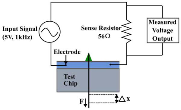
Experimental setup where a sinusoidal input signal is applied to the test chip. The displacement of the muscle wire is varied and the corresponding force is obtained from the force gauge. The change in amplitude of the output voltage signal is used to calculate the magnitude of the impedance.
V. Results and Discussion
For determining the pull force required for a complete valve closure, we tested all the four valve designs, i.e. squeeze valves, SV0.5, SV1.5 and plunger valves PV0.75 and PV0.85 using impedance measurements as described in the earlier section. Fig 4 (top) shows the impedance vs force characteristics of squeeze valves. The general upwards trend of force-impedance curves, can be explained simply by replacing the impedances by ionic resistances. The SV1.5 valve impedance was measured to be 9.5kΩ, satisfying our set design criterion for maximum open valve impedance for SDCS. However, even for a force as large as 120 grams, the valve could not be closed completely, as indicated by a 3-fold increase in final valve impedance. In contrast, closure force for SV0.5 was found to be 52 grams, very close to the 36 grams design valve criterion. However, its open valve impedance was measured to be around 95 kΩ, substantially higher than the allowed maximum open valve impedance. These results conclude that both squeeze valve designs fail the feasibility test for SDCS and considerable design improvements are needed.
Fig. 4.
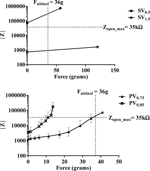
(top) Impedance vs applied force characteristics with for the two squeeze valves, SV0.5 and SV1.5. Zopen_max refers to the maximum impedance for an ideal SDCS open valve. (bottom) Impedance vs applied force characteristics for the two plunger valves, PV0.75 and PV0.85 with a plunger height of 0.75mm and 0.85mm respectively. Each point in the plot represents a mean value ± S.D. of the measured quantities. n=3
The force-impedance analysis of PV valves with the plunger height of 0.75 mm and 0.85 mm can be seen in Fig 4 (bottom). For the PV0.75 valve, the initial open valve impedance was measured to be 1 kΩ while for the PV0.85 valve it was 5 kΩ, both passing the initial test for the low open channel impedance.
Figure 5 (top) shows the plot of applied force vs normalized impedance for both PV valves. In the same plot, we highlighted the 10-fold valve increase to visually depict the closure criterion. Both PV valve designs were found to be much more sensitive than the SV valves, with PV0.85 requiring lower force and travel distance to close as compared to PV0.75. The PV0.75 valve with a plunger height of 0.75 mm required a force of 32 grams for 10-fold impedance increase. The PV0.85 valve with a longer plunger of 0.85 mm, required only a force of 14 grams for its closure. This change in the valve sensitivity can be attributed to the structural design and improved bending characteristics by incorporation of the plunger on the membrane.
Fig. 5.
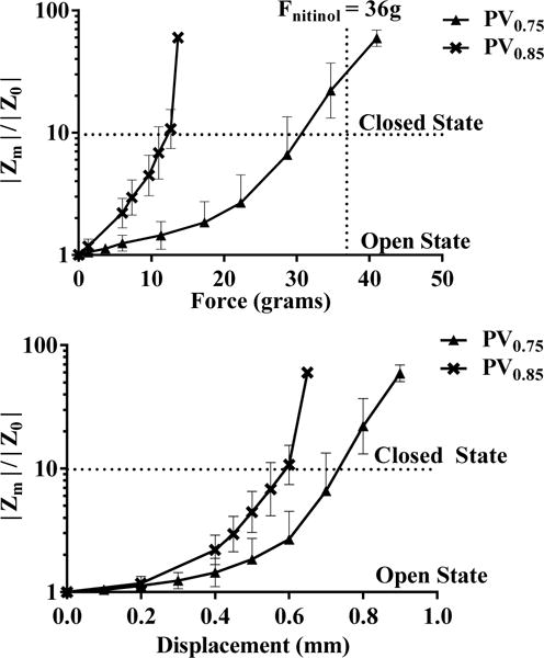
(top) Normalized impedance characteristics for the plunger valves PV0.75 and PV0.85 with varying actuation force. (bottom) Normalized impedance characteristics for the plunger valves with respect to wire displacement. Each point in the plot represents a mean value ± S.D. of the measured quantities. n=3
Whether or not a valve can be considered “closed” depends on the impedance chosen to represent the “closed” state. While driving the plunger to the level of the channel (e.g. 0.15mm for PV0.85) makes a theoretical contact, the microleaks between the plunger and the channel will maintain some level of ionic conduction. Therefore a higher force may be required to attain valve “closure”.
For understanding the membrane deformation of the SV and PV valves, we plotted the normalized channel impedance values as a function of the nitinol muscle wire displacement in Fig 5 (bottom). While it’s difficult to measure the displacement of the plunger, the plot gives an insight to the amount of displacement needed for the required closure. The PV0.75 and PV0.85 valve required a displacement of 0.6 mm and 0.75 mm respectively to achieve valve closure. These results confirm our hypothesis that by increasing the height of the plunger, the valve sensitivity is enhanced. However, there is an optimal plunger height beyond which further increase will violate the initial open valve impedance criterion for SDCS.
VI. Conclusion
In this paper, we examine two valve designs, squeeze valve and plunger valve for their feasibility in SDCS technology. Two feasibility criterions were used other than the valve footprint: 1) maximum allowed initial open valve impedance of 35 kΩ as dictated by safety and power requirements of the SDCS system design and 2) maximum complete valve closure force of 36 grams as set by the nitinol wire manufacturers for reversible long-term actuation. We found that both the squeeze valve designs could not satisfy the feasibility test, whereas both the PV valves designs passed the feasibility criterions. From the results obtained, it can be safely concluded that the channel depth and plunger height are two most crucial parameters that dictate the PV valve performance. By increasing the height of the plunger, the required pull forces can be decreased but at the same time the initial open valve impedances increases. An optimization screen is thus needed as a next step to minimize the power requirement of operating PV valve.
Fig. 2.
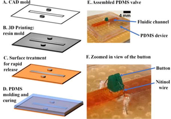
(A)–(D) General steps involved in the fabrication process of the chip. (E) Photograph of an assembled PDMS valve. The fluidic channel was visualized using an orange color food dye. (F) Zoomed-in view showing the resin button around which the nitinol wire is looped.
Footnotes
We believe the present work shows proof-of-concept for the muscle-wire actuated valves. Further testing and optimization may be required to guarantee longevity of operation.
Contributor Information
Chaojun Cheng, Mechanical Engineering, Johns Hopkins University, Baltimore, USA.
Raviraj Thakur, Otolaryngology HNS, Johns Hopkins University, Baltimore, USA.
Ankitha Rajagopalan Nair, Biomedical Engineering, Johns Hopkins University, Baltimore, USA.
Scott Sterrett, Biomedical Engineering, Johns Hopkins University, Baltimore, USA.
Gene Fridman, Otolarynology HNS, Johns Hopkins University, Baltimore, USA.
References
- 1.Guenther T, Lovell NH, Suaning GJ. Bionic vision: system architectures – a review. Expert Rev Med Devices. 2012 Jan;9(1):33–48. doi: 10.1586/erd.11.58. [DOI] [PubMed] [Google Scholar]
- 2.Wilson BS, Dorman MF. Cochlear implants: A remarkable past and a brilliant future. Hear Res. 2008;242(1):3–21. doi: 10.1016/j.heares.2008.06.005. [DOI] [PMC free article] [PubMed] [Google Scholar]
- 3.Rose TL, Robblee LS. Electrical stimulation with Pt electrodes. VIII. Electrochemically safe charge injection limits with 0.2 ms pulses (neuronal application) IEEE Trans Biomed Eng. 1990;37(11):1118–1120. doi: 10.1109/10.61038. [DOI] [PubMed] [Google Scholar]
- 4.Gerges M, Foldes EL, Ackermann DM, Bhadra N, Bhadra N, Kilgore KL. Frequency- and amplitude-transitioned waveforms mitigate the onset response in high-frequency nerve block. J Neural Eng. 2010 Dec;7(6):66003. doi: 10.1088/1741-2560/7/6/066003. [DOI] [PMC free article] [PubMed] [Google Scholar]
- 5.Fridman GY, Della Santina CC. Safe Direct Current Stimulation to Expand Capabilities of Neural Prostheses. IEEE Trans Neural Syst Rehabil Eng. 2013 Mar;21(2):319–328. doi: 10.1109/TNSRE.2013.2245423. [DOI] [PMC free article] [PubMed] [Google Scholar]
- 6.Fridman GY, Della Santina CC. Safe direct current stimulator 2: Concept and design,” in. 2013 35th Annual International Conference of the IEEE Engineering in Medicine and Biology Society (EMBC) 2013:3126–3129. doi: 10.1109/EMBC.2013.6610203. [DOI] [PMC free article] [PubMed] [Google Scholar]
- 7.Vyawahare S, et al. Electronic control of elastomeric microfluidic circuits with shape memory actuators. Lab Chip. 2008 Aug;8(9):1530. doi: 10.1039/b804515a. [DOI] [PubMed] [Google Scholar]


