Abstract
Commercially available neuroprostheses, while successful and effective, are limited in their functionality by their reliance on pulsatile stimulation. Direct current (DC) has been shown to have great potential for the purposes of neuromodulation; however, direct current cannot be applied directly to neurons due to the charge injection thresholds of electrodes. We are developing a Safe Direct Current Stimulator (SDCS) that applies ionic direct current (iDC) without inducing toxic electrochemical reactions. The current design of the SDCS uses a series of eight valves in conjunction with four electrodes to rectify ionic current in microfluidic channels. This paper outlines the design, implementation, and testing of the electronics of the SDCS. These electronics will ultimately be interfaced with a separate microfluidic circuit in the device prototype. Testing the outputs of the electronics confirmed adherence to its design requirements. The completion of the SDCS electronics enables the further development of iDC as a mechanism for neuromodulation.
Index Terms: implants, neural engineering, electrical stimulation, direct current, prosthetics
I. Introduction
Commercial implantable neuroprostheses employ biphasic pulsatile stimulation, in which stimulation waveforms have both a cathodic phase and an anodic phase to pass charge in both directions. While these prostheses are effective for a variety of applications, the stimulation paradigm they employ possesses drawbacks that limit the range of potential applications. Inhibition is difficult to achieve with these devices, as biphasic pulsatile stimulation necessitates both anodic and cathodic phases. At lower frequencies, the switching between these phases generates action potentials, making direct inhibition impossible at the site of stimulation. As a result, prostheses such as deep brain stimulators and spinal cord stimulators function by exciting neurons that have inhibitory projections to the neuron of interest rather than directly inhibiting the target neuron itself [1], [2]. This methodology also results in phase locking to the stimulation frequency, which can be an issue if the natural firing pattern of the neuron needs to be preserved. At higher frequencies of approximately 1-30 kHz, biphasic pulsatile stimulation can block the propagation of action potentials, but only after an initial excitatory phase ranging from 50 milliseconds to as long as 30 seconds [3], which is undesirable for applications such as pain suppression. While biphasic pulsatile stimulation has proven to be effective, alternative neuromodulation technologies may be necessary in applications in which biphasic stimulation is not suitable.
Using direct current (DC) as a means of neuromodulation possesses several advantages over biphasic pulsatile stimulation. At low charge densities, anodic DC reduces neural sensitivity and spontaneous firing rate, while cathodic DC increases sensitivity and firing rate [4], [5]. At higher charge densities, DC is capable of producing a complete neural block [6]. Thus, DC offers more versatility than pulsatile stimulation, as excitation, inhibition, and neural block are possible within the same stimulation paradigm. Additionally, by modulating the chance of an action potential firing as opposed to directly inducing an action potential, DC produces an arguably more natural firing pattern that is not phase locked to a stimulation frequency. Given these advantages, DC has the potential to expand the capabilities of neuroprostheses.
The primary drawback of applying DC to neurons is safety. Neurons cannot survive in the presence of the oxidation and reduction reactions caused by sustained current across an electrode-electrolyte interface. The amount of charge that can be passed in one direction through an electrode-electrolyte interface without causing these faradaic reactions is known as the charge injection limit. The application of DC through conventional metal electrodes inherently violates this charge injection limit because charge always flows in one direction. Thus neuromodulation has primarily revolved around the use of biphasic charge balanced stimulation in which the direction of current constantly changes [7]. If the safety concerns were addressed, DC could potentially be used either by itself or in conjunction with biphasic pulsatile stimulation to allow implantable neuroprostheses to be used in a wider range of applications.
II. Safe Direct Current Stimulator Concept
Previous work in neurophysiology suggests that the application of ionic direct current (iDC) should in theory be both safe and effective for the purposes of neural stimulation [8]. We are currently developing the technology for an implantable safe direct current stimulator (SDCS) that can safely apply iDC to neural tissue. We accomplish this through passing alternating current through an isolated fluid network and rectifying the resulting ionic current through a series of valve actuations. We established an initial proof of concept design, named SDCS1, utilizing saline filled tubing as the isolated fluid network [8]. Fig 1A illustrates the conceptual design and operation of SDCS1. Pairs of valves open and close in phase with a switching current source, altering the path of current such that the direction of the output current remains constant. Rectification was accomplished through manually cycling the valves between the two states depicted in Fig 1A.
Fig 1.
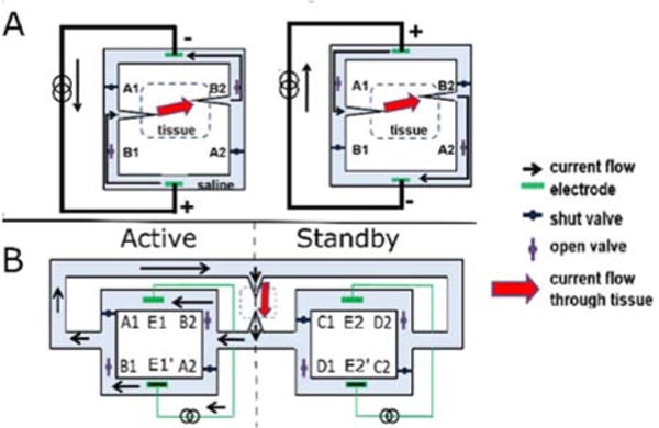
A) SDCS1 Conceptual Design. The two valve and current source configurations required for rectification are shown. The path of current is altered such that the direction of current applied to the tissue remains constant. The design resulted in interruptions in current during valve transitions. B) SDCS2 Conceptual Design. While the active system provides current, the standby system changes its valve configuration, preventing interruptions in current. The two systems alternate between active and standby. One of the twelve valve/electrode states is depicted. Adapted from [8], [9].
SDCS1, while successful in rectifying ionic current, produced interruptions in current at every transition between the two states due to non-ideal valve actuation times. Interruptions in current can potentially induce unwanted action potential firing, making the initial design unsuitable for neural control, particularly in cases where inhibition is desired. To eliminate these interruptions, we introduced SDCS2, an updated design of the SDCS that interleaves the operation of two SDCS1 systems. While one of these SDCS1 systems, designated active, supplies the current to the tissue, the other system, designated standby, switches its valve configuration. Each system alternates between the active and standby modes, ensuring that each system switches valve configurations only when its electrodes are not actively passing current. The overall system cycles through 12 configurations, or states, to produce iDC. This dual SDCS design was successful in eliminating the current interruptions observed with the previous design. Fig 1B illustrates the conceptual design for SDCS2. The complete state machine implementation and data for the SDCS2 design are described in [9].
These previous designs were implemented on a large scale, utilizing large valves and tubing to form the isolated fluid network in which ionic current is rectified. The goal for our project is to develop the SDCS into an implantable neural prosthesis. As a result, we are developing the next iteration of the SDCS design with an emphasis on miniaturization and automation. To reduce the scale, we intend to implement the isolated fluid network as a network of microfluidic channels with nitinol wire valves, which close or open depending on the current passing through the wire [10]. These microfluidics will interface with electronics that control the overall operation of the device. This paper will focus on the design, implementation, and testing of the electronics of the updated SDCS design.
III. Circuit Design
A. Block Diagram
A block diagram of the electronics and its intended interface with the microfluidics is shown in Fig. 2. A power regulation block scales the input voltage for use with other components. We implement a finite state machine using the microcontroller to cycle through each of the 12 states, controlling the operation and timing of the valve controllers and switching current driver. Each valve controller opens or closes a single valve depending on the signal received from the microcontroller. The switching current driver determines which electrodes are passing current and in what direction (which system is designated active or standby). The current feedback circuit takes in a measurement of the applied ionic current being generated through the F+ and F− inputs and adjusts the electrode voltages if the valve impedances are mismatched. VCTRL represents the control signal that specifies the desired output iDC from the device.
Fig. 2.
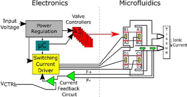
A block diagram of the electronics and its interface to the microfluidic component of the device.
B. Power Regulation
The power regulation block takes in the input voltage from a power source external to the printed circuit board (PCB). The input voltage is first passed through a step-up converter, which can scale a wide variety of input voltages up to 5V, allowing the device to be powered by a 3.7 V rechargeable lithium ion battery. The 5V line powers components such as the microcontroller and comparator of the feedback circuit. The 5V signal is also scaled up with a step-up converter to 25 V to provide the compliance voltage for the switching current driver.
The nitinol wires used in our valve design possess strict stress and strain requirements that must be met to ensure longevity. Adhering to these requirements necessitates fine control of the current applied to these wires. As a result, we have implemented a variable step-down converter to scale the voltage (therefore the current because the wires possess a constant, known resistance) that is applied to the wires from 5 V to 0.85 V.
C. Valve Controllers
The current through each of the individual nitinol wires is controlled by the microcontroller using a transistor placed in series with a nitinol wire. Current can only pass through the wire if a digital high is sent from the corresponding microcontroller output to the gate of the transistor.
D. Switching Current Driver
The switching current driver determines which electrodes pass current to the metal electrodes shown in Fig 1B. The design of the switching current driver relies primarily on two multiplexors (implemented with a MAX14753 chip) controlled by the same signal S, which is composed of two digital outputs from the microcontroller. The S signal determines which electrode is connected to the 25 V and which electrode is connected to the path to ground. The remaining electrodes are disconnected. A diagram of the switching current driver implementation is shown in Fig. 3.
Fig. 3.
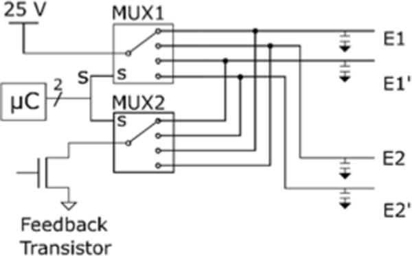
Schematic of the switching current driver. The microcontroller sends a digital signal to two multiplexors to determine which electrodes are connected to the high and low lines. Note that every electrode is attached to an output capacitor connected to ground to prevent switching artifacts during state transitions.
E. Current Feedback Mechanism
Variations in valve impedance, if not compensated for, may result in variations in the applied current amplitude. Ultimately, the variance in valve impedance may be insignificant in the final design of the microfluidics. However, in the interest of robustness we designed the SDCS to utilize feedback control, which necessitates an accurate measurement of current. For the SDCS, this measurement must be of ionic current because we are interested in applying iDC. We placed a fixed length of tube filled with saline agar in series with the tissue path. The tube has a fixed impedance which allows it to function as an ionic sense resistor that we refer to as a current sensing element (CSE) [8].
Fig. 4 depicts the current feedback circuit we implemented. The voltage signal across the CSE is connected to the F+ and F− signals and amplified by an AD8421 instrumentation amplifier. The output of this stage is limited to 5 V by a Zener diode. This amplified signal is connected to a MCP6002 comparator that compares this signal to a control voltage VCTRL (Fig. 2, 4). The output of the comparator is passed through a low pass filter. The output of the filter connects to the gate of a transistor in series with the overall current.
Fig. 4.
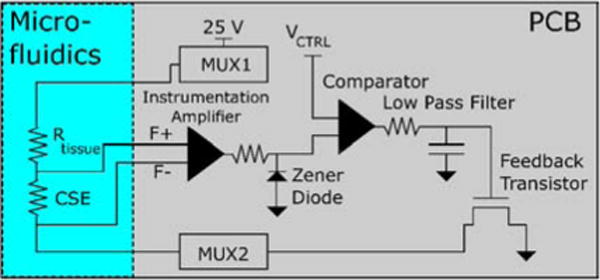
Diagram of the current feedback mechanism. VCTRL is an input signal used to control the current applied to the tissue. The feedback transistor and multiplexors are the same components referenced in Fig. 3.
VCTRL is an adjustable voltage that is used to control the amplitude of the current. The feedback circuit constantly adjusts the current level until the output of the instrumentation amp matches VCTRL. If the current is too high, the output of the comparator lowers, causing the transistor to allow less current to pass. If the current is too low, the opposite occurs. The low pass filter (100 msec time constant) prevents the system from overcompensating and causing instability. Assuming reasonable changes in impedance (<10 Hz in frequency, amplitude range dependent on CSE impedance) the applied current is kept at a constant level proportional to VCTRL.
IV. Methods
This section will cover testing the electronics for proper functionality. We tested the capability of the electronics to provide the necessary outputs that when interfaced with the microfluidics (in development) will be able to produce iDC. The testing was divided into two modules: the state machine implementation testing and the current output testing.
A. State Machine Implementation Testing
Proper functionality of the finite state machine was confirmed by monitoring the outputs of the device and constructing a timing diagram based on the resulting output waveforms. For the valve controller testing, the nitinol wires were simulated with 10 ohm resistors. The differential voltage across each individual valve resistor was measured and converted to current. For the switching current driver, sense resistors were placed in series with each electrode output. Every electrode was then immersed in a 0.9% saline to simulate the interconnections between the electrodes in the microfluidics. For every electrode, the voltage across its sense resistor was measured and converted to a discretized measurement. The output measurements were taken over a period of 25 seconds, with transitions programmed to occur every second as specified in the SDCS2 design [9].
B. Current Output Testing
We designed an experiment to test the ability of the feedback circuit to compensate for a changing ionic impedance path, which may occur if valve impedances are mismatched. The microfluidic path was simulated using a tube filled with 1M saline agar. The CSE was implemented as a small length of the agar filled tube with electrodes placed a fixed distance apart such that there was a constant resistance between the two electrode sites. The resistance of the path (outside of the CSE region) was changed at the same time scale as valve actuation time using a tubing clamp. The voltages were measured across the CSE and across the region of tubing with the tubing clamp. The voltage across the tubing clamp region serves as an estimate of the changing impedance. The voltage across the CSE is proportional to the current because the CSE has a constant impedance. Fig. 5 shows a diagram of the experimental setup.
Fig. 5.
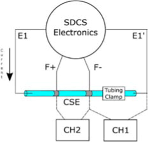
Experimental setup for testing the changing resistance current.
V. Results
A. Form Factor/Miniaturization
The current design is assembled on a circular PCB approximately 23 mm in diameter. An image of the assembled electronics board can be found in Fig. 6.
Fig. 6.
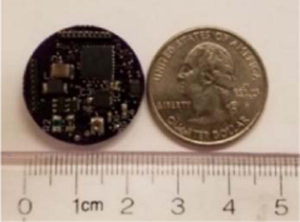
Image of the assembled SDCS PCB compared to a U.S. quarter.
B. Timing Diagram
Fig. 7 shows the timing diagram of the outputs of the valve controllers and the switching current driver. The results are consistent with the valve and current source configurations necessary to produce iDC, described in [9].
Fig. 7.
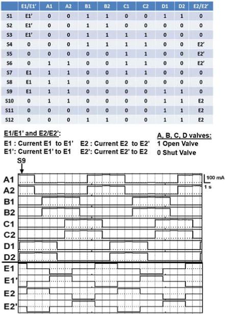
(Top) Table of required states of valves and electrodes described in [9]. (Bottom)Timing Diagram of the outputs of the valve controllers and the switching current driver. Vertical lines indicate state transitions. For the valves, high current corresponds to an open valve, while low current corresponds to a closed valve. Note that the electrode measurements are discretized, with a 0 indicating that the electrode is disconnected, a 1 indicating that the electrode is connected to the 25 V high line, and a −1 indicating that the electrode is connected to the path to ground.
C. Current Output Measurements
Fig. 8 shows the response of the circuit to changes in impedance introduced at approximately the same time scale as valve transitions. While the voltage across the tissue path fluctuated by a maximum of 17%, the current experienced a 3% maximum fluctuation. These results indicate a stable output for the SDCS, which should be robust when switching between valves with mismatched impedances.
Fig. 8.
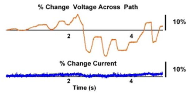
Current response to changing impedance. The orange line (top) corresponds to the percent change in voltage across the entire current path (estimate of impedance % change). The blue line (bottom) shows the % change in applied current. Without feedback, the current output would vary with the changes in the path impedance according to Ohm’s Law.
VI. Conclusion
We have presented the design, implementation, and testing of the electronics for a miniaturized SDCS. We have demonstrated the capability of the electronics to cycle through the valve and electrode configurations required to produce iDC. The current feedback mechanism stabilized the output current of the SDCS, suggesting our design is capable of compensating for variations in valve impedances. The footprint of the electronics has been reduced to a 23-mm diameter circle.
The development of the electronics is a significant step towards realizing a working SDCS prototype. Ultimately, the SDCS is a complex device that requires multiple pieces to function properly to produce iDC. The completion of the electronics will allow us to focus our efforts in other areas such as the microfluidics or the electrode design. Further development will pave the way for chronic animal experiments, allowing a full exploration of long-term iDC safety and effectiveness in-vivo in the near future.
Contributor Information
Patrick Ou, Department of Biomedical Engineering, Johns Hopkins University, Baltimore, MD, USA.
Gene Fridman, Department of Biomedical Engineering, Johns Hopkins University, Baltimore, MD, USA.
References
- 1.Deniau J-M, Degos B, Bosch C, Maurice N. Deep brain stimulation mechanisms: beyond the concept of local functional inhibition. Eur J Neurosci. 2010 Oct;32(7):1080–1091. doi: 10.1111/j.1460-9568.2010.07413.x. [DOI] [PubMed] [Google Scholar]
- 2.Meyerson BA, Linderoth B. Mode of Action of Spinal Cord Stimulation in Neuropathic Pain. J Pain Symptom Manage. 2006;31(4):S6–S12. doi: 10.1016/j.jpainsymman.2005.12.009. [DOI] [PubMed] [Google Scholar]
- 3.Ackermann DM, Bhadra N, Foldes EL, Kilgore KL. Conduction block of whole nerve without onset firing using combined high frequency and direct current. Med Biol Eng Comput. 2011 Feb;49(2):241–251. doi: 10.1007/s11517-010-0679-x. [DOI] [PMC free article] [PubMed] [Google Scholar]
- 4.Hopp FA, Zuperku EJ, Coon RL, Kampine JP. Effect of anodal blockade of myelinated fibers on vagal C-fiber afferents. Am J Physiol. 1980 Nov;239(5):R454–62. doi: 10.1152/ajpregu.1980.239.5.R454. [DOI] [PubMed] [Google Scholar]
- 5.Goldberg JM, Smith CE, Fernández C. Relation between discharge regularity and responses to externally applied galvanic currents in vestibular nerve afferents of the squirrel monkey. J Neurophysiol. 1984 Jun;51(6):1236–56. doi: 10.1152/jn.1984.51.6.1236. [DOI] [PubMed] [Google Scholar]
- 6.Bhadra N, Kilgore KL. Direct Current Electrical Conduction Block of Peripheral Nerve. IEEE Trans Neural Syst Rehabil Eng. 2004 Sep;12(3):313–324. doi: 10.1109/TNSRE.2004.834205. [DOI] [PubMed] [Google Scholar]
- 7.Merrill DR, Bikson M, Jefferys JGR. Electrical stimulation of excitable tissue: design of efficacious and safe protocols. J Neurosci Methods. 2005 Feb;141(2):171–198. doi: 10.1016/j.jneumeth.2004.10.020. [DOI] [PubMed] [Google Scholar]
- 8.Fridman GY, Della Santina CC. Safe Direct Current Stimulation to Expand Capabilities of Neural Prostheses. IEEE Trans Neural Syst Rehabil Eng. 2013 Mar;21(2):319–328. doi: 10.1109/TNSRE.2013.2245423. [DOI] [PMC free article] [PubMed] [Google Scholar]
- 9.Fridman GY, Della Santina CC. Safe direct current stimulator 2: Concept and design. 2013 35th Annual International Conference of the IEEE Engineering in Medicine and Biology Society (EMBC) 2013;2013:3126–3129. doi: 10.1109/EMBC.2013.6610203. [DOI] [PMC free article] [PubMed] [Google Scholar]
- 10.Vyawahare S, et al. Electronic control of elastomeric microfluidic circuits with shape memory actuators. Lab Chip. 2008;8(9):1530. doi: 10.1039/b804515a. [DOI] [PubMed] [Google Scholar]


