Abstract
Bioimaging is currently undergoing an exciting revolution. This includes all aspects of imaging from probe development, specimen preparation, and instrumentation to image analysis and quantitation. Perhaps the most exciting developments are new platforms for imaging that radically advance the capabilities for collecting high spatial and temporal resolution data. In many cases, the standard microscope has been replaced with new purpose-built platforms that are much more flexible, and enable the implementation of new imaging modalities. such as particular single molecule and superresolution imaging methods.
I. Introduction
For live cell imaging, there are a number of competing critical requirements. Any live cell imaging system must be physically stable, so that vibrations and temperature shifts do not move the sample or the optical path. This requirement is undermined by the need to change focus and collect images as rapidly as possible. Fast live cell imaging thus requires a very stable, rapidly and accurately moving imaging system, with little vibration or temperature changes. Photobleaching and photodamage lead to the photon budget, the number of photons transmitted through the microscope, becoming limiting. When working at photon-limited levels, any additional sources of background and noise, such as from stray light or camera electronics, must be avoided. A recent study has highlighted the presence of additional non-Poisson noise in all tested commercial imaging platforms (Murray et al., 2007). Thus, photon-limited imaging is extremely challenging on traditional microscope platforms.
In this chapter, we discuss the design principles and applications of the OMX microscope, a new microscope platform designed and built by John Sedat (UCSF). OMX has been designed to provide unprecedented mechanical and thermal stability coupled with a photon budget that is dramatically improved over traditional microscope platforms. These characteristics make an outstanding platform for fast live cell imaging and superresolution imaging. Moreover, its open, flexible architecture make it particularly amenable to adding other modes of microscopy to the platform.
II. History and Design of OMX
OMX was designed and developed by John Sedat in collaboration with Dave Agard (both at UCSF) and a number of coworkers, such as Mats Gustafsson (now at Janelia Farm Research Center), Lukman Winoto and Pete Carlton. The microscope's name is derived from the original name given by Agard and Sedat to their first widefield deconvolution microscope Optical Microscope 0 (OM0). OM0 was based on a Zeiss Axiomat, with LN2-cooled CCD camera from Texas Instruments, run from a VAX8650 mainframe computer. OM0 was used to acquire the first three-dimensional fluorescence images of cellular structures (Agard and Sedat, 1983). There followed OM1, a turnkey, Silicon Graphics workstation-controlled microscope that included fiber-optic illumination and stage-based focusing on an inverted microscope that provided some of the first three-dimensional fluorescence images of living cells passing through the cell cycle (Minden et al., 1989) and was later commercialized as the DeltaVision microscope (Applied Precision, Inc.), which continued its own path of development. OMX stands for "eXperimental", as the microscope is a continuously evolving platform that allows further development and improvement.
Traditional microscope stands have to take into account optical performance, cost and ease of use. The optical path is designed to accommodate both a range of additional components and the microscopist sitting at the microscope using the eyepieces and controls. Consequently, the efficiency of light transmission and suppression of stray light are compromised. Additionally, it is difficult to rapidly and efficiently capture two channels simultaneously in wide-field microscopes, and capturing three or four simultaneously is nearly impossible. Although laser scanning confocals can often capture multiple channels simultaneously, they are relatively slow, taking seconds to minutes per image stack, and have much lower photo efficiency (Murray et al., 2007). OMX was designed and built to provide a flexible platform that would be a foundation for many different modes of microscopy and reduce the limitations found in conventional microscope platforms.
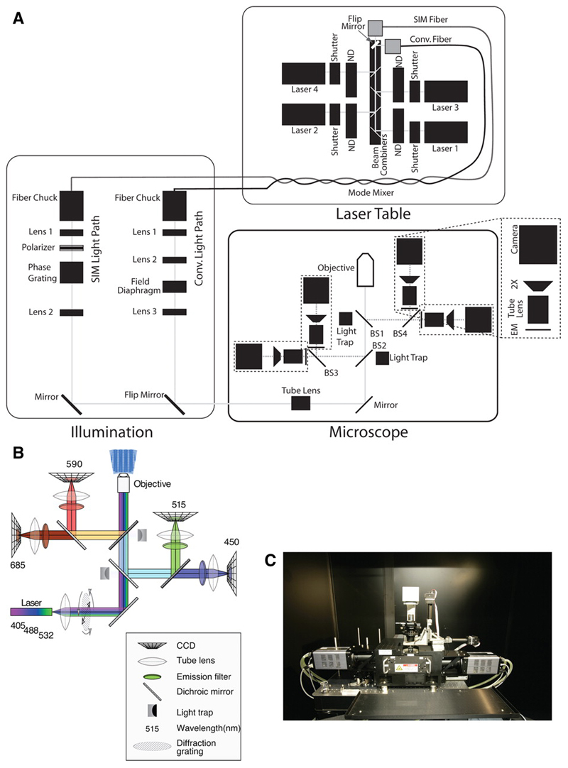
OMX includes separate modules for illumination, imaging, microscope control, and locating the sample. The layout and individual components are shown in Figure 1. For illumination, OMX uses solid-state continuous wave lasers to provide monochromatic, bright illumination. At least 5 separate lasers can be installed in the laser bed. Shuttering is achieved using individual solenoids that can operate reliably down to 1 msec opening time, and 6-position wheels carrying neutral density filters provide attenuation to control the excitation light intensity very precisely. At any time, all active lasers are focused into one of two fibers that provide alternative light paths into the microscope body. In the current implementation of OMX, one path is used for fast live cell imaging using conventional optics and the other for 3D Structured Illumination Microscopy (3DSIM). As described below, the flexible, open design of OMX allows many alternative configurations.
Figure 1. OMX Components and Layout.
(a) Schematic of the optical setup of OMX, courtesy of Paul Goodwin, API. Used by Permission (b) The light path for the “live-cell” drawer configuration to enable the use of CFP/YFP and GFP/mCherry (c) photograph of the OMX microscope body.
The microscope is based on a solid metal block platform, drilled to allow fitting of components. The block holds a kinematically mounted “drawer” that contains the elements of the fluorescence light path. This base is mounted on an anti-vibration table, and the whole assembly is housed in an acoustically isolated, thermally controlled room. For fluorescence, the light path has been optimized to collect emission light, somewhat at the expense of excitation light. This block-and-drawer configuration replaces the standard microscope stand. The stage and lens mounting is made of Invar, a nickel-steel alloy with a very low coefficient of thermal expansion. Instead of using a rotating turret with a focus knob to raise, lower, and quickly change objectives, OMX objectives are fixed into kinematically mounted Invar plates, adding stability and reproducibility. Focus change for optical sectioning is achieved by a piezoelectric device that changes the position of the stage and sample, while leaving the lens fixed in place. Two Nanomover motors (Melles Griot) are used for translation in the image plane. There are no binoculars, and the microscope is kept isolated from the user in a temperature regulated, filtered environment. Up to four separate cameras can be mounted on OMX, enabling fast and simultaneous multi-channel data acquisition.
The fluorescence drawer used in OMX contains four beamsplitters (BS1~4) that direct emitted light to the cameras (Figure 1). The central beamsplitters (BS1 and BS2) permit all wavelengths of excitation light to pass through virtually unreflected; the very small amount of reflected light is blocked by light traps, suppressing stray light and hence reducing background. Emission light returning from the sample is reflected by the beamsplitters to the appropriate cameras. First, both red and far-red light are reflected by BS2 to the left, where BS3 reflects red light to one camera and allows far-red light to pass through to another. Green and blue light pass through BS2, but both are reflected by BS1 to BS4, which directs green light to one camera and allows blue light to pass through. Drawers containing different beamsplitter arrangements may be easily swtiched in and out to allow simultaneous imaging of various combinations of fluorophores. Multiple cameras and a simply exchanged filter assembly allow the emitted light to be split in other ways, such as by polarization.
OMX is controlled by a group of Windows based computers that provide all user interfaces and control of the cameras, shutters, and other devices. The software controlling the system is written in C++ and Python. The Python source code is directly accessible on the computer during active operation, and can be modified and re-loaded at will. Users can issue commands or create new scripts via the built-in Python interpreter to control operation of the microscope at many levels, at any degree of sophistication desired. This flexibility allows complex illumination strategies such as those required for PALM type experiments to be easily implemented. All functions running on auxiliary computers are accessible from the main control computer over the network, via the Pyro distributed object system (http://pyro.sourceforge.net/). Most user actions are saved to logs, so imaging sessions can be exactly recreated, or debugged in case of problems. Furthermore, the temperature of the stage, the microscope body, the motors, and the entire room is continuously monitored and saved to disk, so users are aware of any possible irregularities.
In order to make sample finding and setup easy the OMX microscope uses a dedicated conventional auxiliary microscope (LMX). The LMX microscope has a range of high working distance objectives, with both transmission and epi-fluorescence illumination. LMX has a high-precision motorized stage used for sample location and mapping. This stage is cross-indexed to the OMX stage in order to allow sharing of coordinates between the two systems. The LMX is configured to enable tile-scanning of the entire region of a conventional slide that is within the stage travel of OMX. This tile scan can then be exported to the OMX control computer and used as a location map for finding specific features or locations once the slide has been mounted on OMX.
The workflow for using OMX for fixed samples involves preparing samples, and first imaging them on the LMX using a tile scan mode in either bright-field or fluorescence. The sample is then moved to the OMX stage, the tile scan is transferred to the OMX control computer and the OMX software is used to locate regions for further imaging. For live cells, a pre-scan can be performed on LMX, and then used as a basis for finding living cells, or the live cell chamber can be directly mounted on OMX and then scanned using the OMX control software. The tile scan is displayed on the screen using texture-mapping, allowing very fast panning and zooming over an entire slide’s worth of image data at high resolution. This arrangement allows the operator to scan the slide at leisure without either illuminating the sample or needing to use eyepieces.
The first OMX prototype, ‘OMX v1’, was designed and built in John Sedat’s lab at UCSF. Applied Precision, Inc. has licensed the OMX design and built a number of beta systems, referred to collectively as ‘OMX v2’. The data in Figures 2–6 are from two OMX v2 systems based at the Universities of Oxford and Dundee.
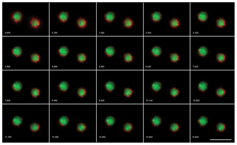
Figure 2. Live Cell Imaging with OMX.
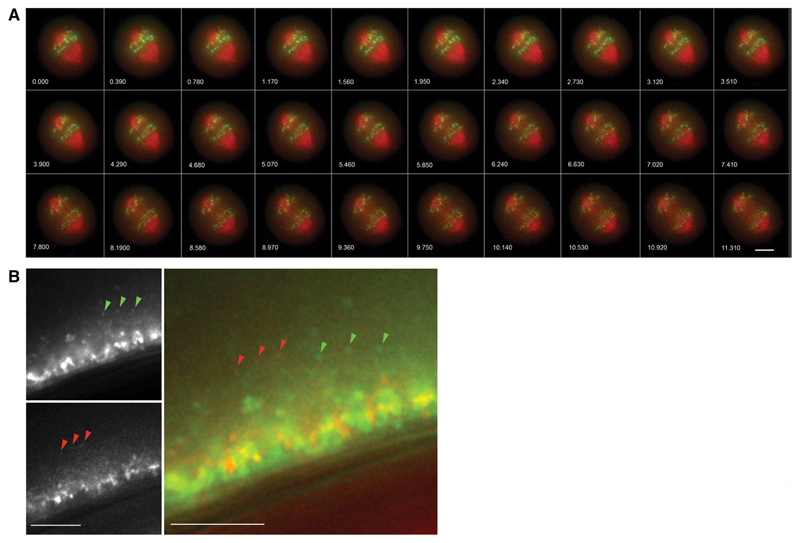
S. cerevisiae with mCherry labeled nuclear pore complexes and GFP-TetO tagged chromosome IV. 13 z-sections, 0.3μm apart, timelapse 780ms. Wavelengths were acquired simultaneously on OMX v2 then aligned and fused. Images have been deconvolved and maximum intensity projected. Scale bar represents 5μm. Numbers indicate elapsed time in seconds. Emma King and David Dickerson (University of Dundee) and Paul Goodwin (API).
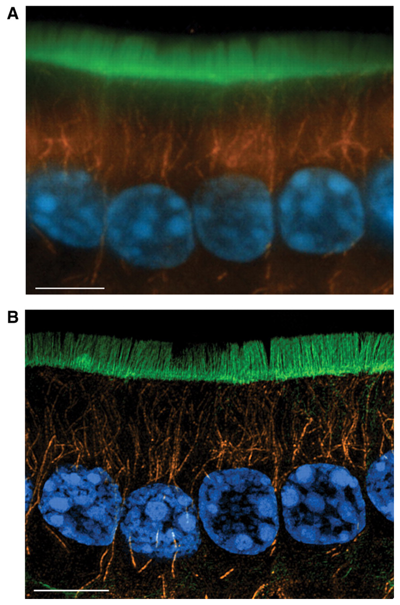
Figure 6. 3DSIM imaging on OMX—cryosections.
10μm cryosection of formaldehyde fixed mouse small intestine, stained with DAPI to show nuclei (blue), anti-tubulin/Alexa Fluor 568 to show microtubules (orange) and FITC-phalloidin to show F-actin (green), (a) deconvolved conventional widefield image, 5 z-section maximum intensity projection, (b) image cquired using the 3DSIM protocol on OMX v2. Wavelengths were acquired sequentially, reconstructed then aligned and fused. 5 z-section maximum intensity projection. Scale bar represents 5μm. Emma King and Paul Appleton (University of Dundee).
III. Imaging Applications using OMX
The first versions of OMX have been outfitted for two specific applications: fast, multi-channel microscopy for high sensitivity and high temporal resolution analysis of living cells, and 3D structured illumination microscopy (3DSIM) for high spatial resolution imaging of fixed cells. In the next sections, we detail the use of these different modes and show examples of the results that can be achieved.
Fast Live Imaging for High Temporal resolution Analysis
Biological processes operate on a wide range of time scales, from sub-millisecond to many minutes. The drive to develop mathematical models of molecular interactions presumes the availability of high quality data sets that properly sample these events. Currently, conventional microscopes can record many single images per second. However when sampling across space (optical sections) and spectral range (as in multi-channel fluorescence microscopy), the practical limit to temporal sampling is on the order of ~1 3D image/second. Any process that occurs on a sub-second timescale is thus subject to temporal aliasing. Furthermore, raw speed of time-lapse acquisition is not necessarily the key parameter to consider, since the efficiency of light transmission and detection determine critically whether useful images can be acquired in any particular set of conditions.
OMX offers two distinct advantages for live cell imaging. First, up to 4 channels can be recorded simultaneously, or in the case of fluorophores with some spectral overlap, in very rapid sequence such that the delay between sampling at different wavelengths is no more that 1-2 msec. Second, the very bright laser light sources, fast shutter, rapid and stable focusing, and the integration of the electronic control mean that very rapid, accurate and precise 3D imaging is achievable. The current implementations of OMX can record 2 – 10 3D images/sec for each channel. The fastest we have run our microscopes, with 1 msec exposure, is 93 or 107 images/sec, depending on the precise individual prototype. The major speed bottleneck is the read time of the cameras, which for a full-frame image (512x512 pixels; 10MHz; 16 bits) is 13 msec. Reducing the imaging area on the CCD substantially reduces this time.
Most live cell imaging applications make use of fluorescent proteins (FPs). Choice of FP is dependent on the laser lines present on the system and on how bright and photostable the proteins are. For simultaneous acquisition of multiple wavelengths, well spectrally separated FPs work best. For example, GFP and mCherry are compatible with the 488 and 593 laser lines, do not spectrally overlap significantly and are relatively photostable. Figure 2 shows two examples of using FP-labelled living yeast and human cells with this mode of imaging.
To date, OMX uses the Bioptechs FCS2 enclosed live-cell imaging system. Samples are grown on or adhered to 40mm (#1.5 thickness) coverslips either by their own adherent properties or by coating slides with substances such as Polylysine or Concanavalin A. The design of the FCS2 system permits temperature control and media exchange, but not an environment in which CO2 is regulated. A critical advance for the future is the design and building of an environmental chamber for live cell imaging.
3D Structured Illumination Microscopy for High Spatial Resolution Analysis
The achievable resolution in light microscopy has been limited to ~λ/2 by diffraction since the development of the modern microscope in the late 1800’s. Over the past few years a number of methods of overcoming this diffraction limit have been developed. These methods are collectively known as “super-resolution” techniques (Hell, 2009)
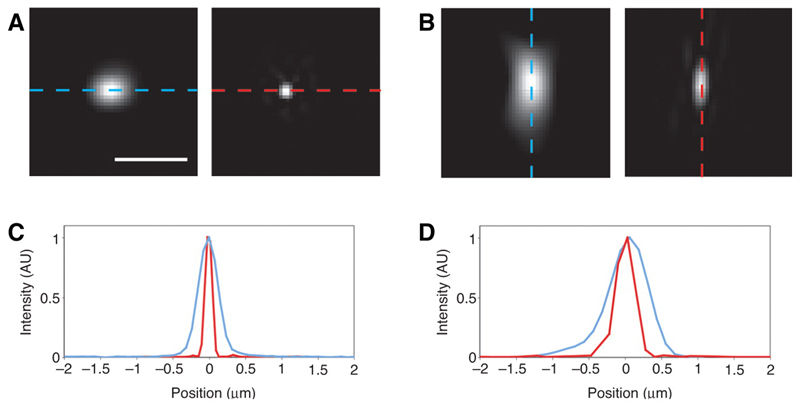
3DSIM uses structure within the illumination and multiple images per sample plane, combined with post acquisition analysis to double the achievable resolution in all 3 spatial dimensions. By illuminating a fluorescent sample with a sinusoidal striped pattern additional information from the sample is encoded in the fluorescent emissions (Gustafsson, 2000; Schermelleh et al., 2008). The phase of the striped pattern is shifted over a full cycle in 5 steps and also rotated to 3 positions, at 60° intervals. The resulting 15 images per Z-plane are processed to produce the final super-resolution image. Images of fluorescent beads, with profiles showing the resolution improvement in both conventional widefield and 3D-SIM are show in Figure 4. The achievable resolution varies from 105 nm with 405 nm illumination to 165 nm with 593 nm resolution (Gustafsson, 2000).
Figure 4. OMX Point-Spread Functions with and without 3DSIM.
Images (a,b) and line scans (c,d) of 89 nm fluorescent beads illuminated at 488 and detected at 510nm in conventional widefield and 3DSIM imaging modes. XY and XZ slices in conventional widefield mode (a) and in a 3DSIM reconstruction (b). Profiles through the centre of a bead clearly showing the increase in resolution between convention widefield (blue) and 3DSIM (red), in both XY (c) and Z (d), demonstrating the increase in resolution is achieved in Z as well as XY. Ian Dobbie (University of Oxford).
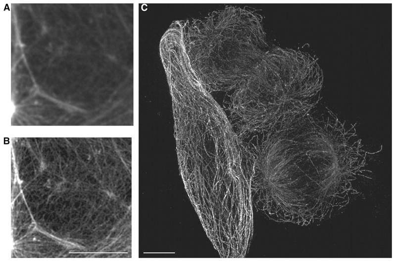
As implemented on the current versions of OMX, 3DSIM is realistically useful for fixed specimens. With that caveat, 3DSIM on OMX has been successfully applied to a broad range of specimens—micro-organisms, vertebrate cells, tissue sections and even whole embryos. Our own microscopes have been used by a variety of collaborators, and these data will be published elsewhere. Figures 5 and 6 show two examples of the application of OMX in cultured macrophages and HeLa cells (Fig. 5) and a section of fixed mouse colon (Fig. 6). The improvement in axial resolution in comparison to conventional deconvolution or confocal imaging is apparent in subcellular structures visible in these images. For example the diameter of microtubule fibres are closer to their true sizes and overlapping and dense fields of microtubules or actin networks can be resolved into individual fibres much more readily.
Figure 5. 3DSIM imaging on OMX—cultured cells.
Drosophila macrophage, fixed and stained for F-actin with FITC-phalloidin. Conventional widefield image (a) and 3DSIM reconstruction (b), clearly showing the dramatic increase in detail achieved. (c) Formaldehyde-fixed HeLa cell stained eith anti-tubulin and Alex Fluor 488 secondary antibody. Image acquired using the 3DSIM protocol on OMX v2. Image shown is a maximum intensity projection through the full volume of the cells. Scale bar represents 5μm. Parts a & b, Ian Dobbie and Ilan Davis (University of Oxford). Part c Jason Swedlow (University of Dundee) and Paul Goodwin (API).
Sample preparation and Imaging Protocols for 3DSIM
Sample preparation for imaging using the structured illumination protocol of OMX does not vary greatly from that used for image acquisition on other systems. However, emphasis needs to be placed on good practice to ensure a specific, bright and photostable fluorescent signal, as well as good morphological preservation. Fixation should be of the highest quality that is consistent with preserving epitopes and the fluorescence of FPs, as appropriate.
The system is designed for use with scrupulously clean #1.5 (1.7mm thick) coverslips with the material to be imaged within 16μm of the surface of the coverslip. Fixation conditions and choice of primary antibody, that localises strongly to the structure of interest, need to be optimised to achieve a good signal to background ratio, thus optimising reconstruction output and minimising the generation of reconstruction artefacts. A broad range of samples have been successfully imaged using the SI protocol of OMX; from cell-monolayers to mouse-gut wax sections and plant leaf peels.
There is a wide choice of bright, photostable secondary antibodies to match the laser lines available on the system allowing excellent image quality by optimizing the match between the filter sysems and the excitation and emmission characteristics of the fluorochromes. We have successfully utilised Alexa Fluor-conjugated secondary antibodies (Invitrogen) and recently Jackson have released a new DyLight collection that further expands the availability of wavelength specific antibodies to target a broader range of primary antibodies raised in different species. The 593 laser line is compatible with both 568 and 594 excitable dyes. Protein fusions fused to a bright FP, such as GFP, can be used for imaging of samples that require a small number of z-steps and/or exposure to a limited number of excitation wavelengths. However the photostability of FPs has so far limited their use in 3D-SIM. Acquisition of images using the 3D-SIM protocol is possible using cameras with EMCCD amplification enabled, which has opened the door to imaging of dimmer samples with low background fluorescence. Furthermore, to protect the fluorescence emitted and to minimise changes of refractive index in the light path, samples should be mounted in a media that matches the refractive index of the objective lens fitted. The mountant should contain anti-fade agents such as 1,4 phenylene diamine (PPD) in 90% glycerol 10% TRIS buffer, which we have found to give optimal results, especially with 594 excitable dyes.
V. Future directions
OMX is fundamentally a research instrument and is still under development. Its basic premise of reworking the fluorescence light microscope from the ground up provides a very flexible new platform. Currently the commercial OMX sold by API is setup for fast live multi-channel imaging and super-resolution 3D-SIM. Adding novel functionality is relatively easy due to the open nature of the excitation light paths and flexability of the hardware and software controls. Some of the possible extensions in functionality are discussed below, although this list is far from exhaustive and is continously evolving.
2DSIM in Living Cells
3D-SIM on OMX is able to double the resolution compared to a conventional fluorescence microscope. However, there are two major drawbacks to the technique. In order to perform 3D-structured illumination at least 5 illumination phases must be recorded at 3 different angles. Therefore for each reconstructed image plane, 15 images must be recorded. This can cause substantial photo-bleaching and results in very slow acquisition due to the large number of images required. Data collection is further slowed by the fact that the current implementation of OMX rotates a physical diffraction grating to take images with the structured illumination at different angles. This process requires approximately 2 seconds per angle change. In order to properly perform reconstructions to provide the higher resolution output image any structure of interest must not move during imaging by a significant fraction of the of the 100 nm resolution. In the current generation of OMX the minimum time to take a full structured illumination Z-series is approximately 10s, long enough for the internal contents of the cell to move substantially more than 100nm. This situation can be improved in two complimentary ways. First, by providing Z-sectioning via TIRF, only a single Z-section is required and the number of images that are captured is reduced to 9, 3 phases at 3 angles. It should be noted that this provides a single plane super resolution image, rather than a 3D image stack. Second, using a spatial light modulator, the diffraction grating angle can be changed without physically moving the optical elements. Combining these two approaches allows single 2D TIRF super resolution images to be collected in less than 100 ms (Kner et al., 2009).
Total Internal Reflection Fluorescence (TIRF)
TIRF is a method for achieving 100nm Z-resolution combined with very low fluorescence background. This is achieved by illuminating the sample with light above the critical angle for complete reflection between the coverslip and the sample. This produces an evanescent wave parrallel to the coverslip which falls exponentially with distance from the interface (see Chapter 37). Multi-wavelength objective based TIRF has been implemented on the Sedat lab OMX by redirecting the standard wide-field illumination into a multi-wavelength single mode fibre. This fibre is then translated in order to shift the position of the beampath in the back focal plane. This allows rapid changes of the angle of incidence to acheive TIRF at different wavelengths for multi colour live TIRF imaging.
3D-TIRF
The precise control of the angle of incidence on OMX also allows the acquisition of TIRF images at a range of angles, all above critical angle. In this way an image stack can be created by steadily imaging further into the sample. Image processing allows calculation of the depth of objects within the image with very high Z resolution. This technique allows imaging with 100 nm Z resolution to depths up to 1 µm.
Image Processing for Live Cell Imaging
A primary design aim of OMX is to maximise the signal to noise ratio (SNR) in order to gather as much data as possible from limited illumination intensity and short exposures that occur in fast imaging of highly photosensitive living cells. Analysing the data generated in fast live imaging requires the implementation of object identification and tracking software that can track rapidly moving particles in images with limited SNR (Jaqaman et al., 2008). These tools are critical for delivering quantitative measurements of objects recorded in live cell imaging (see Ch. 17).
A promising area for future improvement in fast live cell imaging is the use of image processing tools to improve SNR and thus the performance of subsequent analysis tools. Deconvolution, used on 3D data stacks from OMX, is able to improve SNR using the point-spread function to develop an estimate of in-focus object in the sample (Swedlow et al., 1997; Wallace et al., 2001, **Parton and Davis 2006). In addition, the application of de-noising algorithms can substantially improve the appearance of image data, De-noising relies upon the fact that signal but not noise is correlated between adjacent pixels in 2 or 3D. In 2D de-noising is relatively simple and widely applied, using processes such as a Gaussian or a median filter. Extending this to 3D further improves the signal to noise as extra information is available. Recently, more advanced algorithms have become available. By applying denoising techniques to 4D image sets, 3D data in time, even more signal to noise improvement can be gained.
PALM
A second technique for generating so called super-resolution images, with a precision greater than 20 nm, is Photo-Activation Localisation Microscopy (PALM, (Betzig et al., 2006)). This technique works by iteratively building up an image from the fluorescence emission of individual dye molecules imaged in a stochastic manner, a small number at a time. Basic 2-D PALM as described above can be achieved easily on OMX, as it simply requires a custom illumination pattern, low intensity activation pulse, followed by multiple frames of standard excitation imaging. This can either bleach out the active molecules or be followed by a deactivation pulse. Z-position information can be added to this by either taking images at 2 Z-positions (Juette et al., 2008),or using an imaging system with astigmatism (Huang et al., 2008). The multiple cameras and simple filter arrangement on OMX allows multiple Z-positions to be simultaneously acquired using a 50-50 beam splitter between the 2 channels and introducing an extra lens into one channel, producing a focus shift relative to the other channel. Alternatively, astigmatism can be easily introduced by having a cylindrical lens in the illumination path. On OMX this is easily achieved due to the open access to the illumination beam-path.
VI. Concluding Remarks
Due to its flexibility, the OMX platform is still rapidly evolving. We anticipate that many more functionalities will be added to the platform, as essentially all applications of widefield fluorescence microscopy can be improved by taking advantage of the improved light budget, stability and simultaneous acquisition characteristics of the system.
Figure 3. Live cell imaging with OMX.
Mitotic HeLa cell with mCherry labeled tubulin and GFP-CenpB. 3 z-sections, 0.5μm apart, timelapse 390ms. Wavelengths were acquired simultaneously on OMX v2 then aligned and fused. Images have been deconvolved and maximum intensity projected. Scale bar represents 5μm. Emma King and Markus Posch (University of Dundee) and Paul Goodwin (API).
Acknowledgements
We thank Sam Swift, Chris Allan, and Benny Chitambira for help in running the University of Dundee OMX, Paul Appleton, David Dickerson, Markus Posch (University of Dundee) and Paul Goodwin (Applied Precision, inc.) for permission to use their figures in this manuscript. We thank Kim Nasmyth for discussions on the biological applications of OMX, Tim Weil for his help acquiring Swallow and bicoid time lapse images. Use of University of Dundee OMX microscope is supported by the Scottish University Life Sciences Alliance. Work in the Swedlow Lab using OMX is supported by the Wellcome Trust (067433), Cancer Research UK (C303/A5434), and the BBSRC (BB/G01518X/1). ID and RMP are supported by a Senior Research Fellowship from the Wellcome Trust (081858) to ID. OMX was purchased in Oxford with grants from the Wellcome Trust, EPA and OUP Fell Funds.
References
- Agard D, Sedat J. Three-dimensional architecture of a polytene nucleus. Nature. 1983;302:676–681. doi: 10.1038/302676a0. [DOI] [PubMed] [Google Scholar]
- Betzig E, Patterson GH, Sougrat R, Lindwasser OW, Olenych S, Bonifacino JS, Davidson MW, Lippincott-Schwartz J, Hess HF. Imaging intracellular fluorescent proteins at nanometer resolution. Science. 2006;313:1642–5. doi: 10.1126/science.1127344. [DOI] [PubMed] [Google Scholar]
- Gustafsson MG. Surpassing the lateral resolution limit by a factor of two using structured illumination microscopy. J Microsc. 2000;198:82–7. doi: 10.1046/j.1365-2818.2000.00710.x. [DOI] [PubMed] [Google Scholar]
- Hell SW. Microscopy and its focal switch. Nat Methods. 2009;6:24–32. doi: 10.1038/nmeth.1291. [DOI] [PubMed] [Google Scholar]
- Huang B, Wang W, Bates M, Zhuang X. Three-dimensional super-resolution imaging by stochastic optical reconstruction microscopy. Science. 2008;319:810–3. doi: 10.1126/science.1153529. [DOI] [PMC free article] [PubMed] [Google Scholar]
- Jaqaman K, Loerke D, Mettlen M, Kuwata H, Grinstein S, Schmid SL, Danuser G. Robust single-particle tracking in live-cell time-lapse sequences. Nat Methods. 2008;5:695–702. doi: 10.1038/nmeth.1237. [DOI] [PMC free article] [PubMed] [Google Scholar]
- Juette MF, Gould TJ, Lessard MD, Mlodzianoski MJ, Nagpure BS, Bennett BT, Hess ST, Bewersdorf J. Three-dimensional sub-100 nm resolution fluorescence microscopy of thick samples. Nat Methods. 2008;5:527–9. doi: 10.1038/nmeth.1211. [DOI] [PubMed] [Google Scholar]
- Kner P, Chhun BB, Griffis ER, Winoto L, Gustafsson MG. Super-resolution video microscopy of live cells by structured illumination. Nat Methods. 2009;6:339–42. doi: 10.1038/nmeth.1324. [DOI] [PMC free article] [PubMed] [Google Scholar]
- Minden JS, Agard DA, Sedat JW, Alberts BM. Direct cell lineage analysis of Drosophila melanogaster by time-lapse, three-dimensional optical microscopy of living embryos. J Cell Biol. 1989;109:505–516. doi: 10.1083/jcb.109.2.505. [DOI] [PMC free article] [PubMed] [Google Scholar]
- Murray JM, Appleton P, Swedlow JR, Waters JC. Evaluating performance in fluorescence 3-D microscopy. J Microsc. 2007 doi: 10.1111/j.1365-2818.2007.01861.x. In press. [DOI] [PMC free article] [PubMed] [Google Scholar]
- Schermelleh L, Carlton PM, Haase S, Shao L, Winoto L, Kner P, Burke B, Cardoso MC, Agard DA, Gustafsson MGL, et al. Subdiffraction Multicolor Imaging of the Nuclear Periphery with 3D Structured Illumination Microscopy. Science. 2008;320:1332–1336. doi: 10.1126/science.1156947. [DOI] [PMC free article] [PubMed] [Google Scholar]
- Swedlow JR, Sedat JW, Agard DA. Deconvolution in Optical Microscopy. In: Jansson PA, editor. Deconvolution of Images and Spectra. New York: Academic Press; 1997. pp. 284–309. [Google Scholar]
- Wallace W, Schaefer LH, Swedlow JR. A workingperson’s guide to deconvolution in light microscopy. Biotechniques. 2001;31:1076–1097. doi: 10.2144/01315bi01. [DOI] [PubMed] [Google Scholar]


