

Abstract
Introduction:
The purpose of this study was to investigate the systematic localization accuracy, treatment planning capability, and delivery accuracy of an integrated magnetic resonance imaging guided Linear Accelerator (MR-Linac) platform for stereotactic radiosurgery.
Materials and methods:
The phantom for the end-to-end test comprises three different compartments: a rectangular MR/CT target phantom, a Winston–Lutz cube, and a rectangular MR/CT isocenter phantom. Hidden target tests were performed at gantry angles of 0, 90, 180, and 270 degrees to quantify the systematic accuracy. Five patient plans with a total of eleven lesions were used to evaluate the dosimetric accuracy. Single-isocenter IMRT treatment plans using 10–15 coplanar beams were generated to treat the multiple metastases.
Results:
The end-to-end localization accuracy of the system was 1.0 ± 0.1 mm. The conformity index, homogeneity index and gradient index of the plans were 1.26 ± 0.22, 1.22 ± 0.10, and 5.38 ± 1.44, respectively. The average absolute point dose difference between measured and calculated dose was 1.64 ± 1. 90%, and the mean percentage of points passing the 3%/1 mm gamma criteria was 96.87%.
Conclusions:
Our experience demonstrates that excellent plan quality and delivery accuracy was achievable on the MR-Linac for treating multiple brain metastases with a single isocenter.
Keywords: MR-Linac, Stereotactic radiosurgery, Accuracy, Single isocenter multiple targets
Image guidance has been a critical component for target localization in stereotactic radiosurgery via cone beam computed tomography, stereoscopic X-ray imaging, etc. [1,11,25]. However, the technical obstacles in developing an MR-guided radiosurgery system are significant due to the interactions between the magnetic field of an MRI system and the linear accelerator (Linac) system. On the Linac side, many critical components, including the magnetron and port circulator, cannot function properly in the presence of a magnetic field. The magnetic field can also divert both electrons traveling within the beam transport system and secondary electrons generated inside patients [16]. On the MRI side, the high-power radiofrequency energy from the Linac may significantly deteriorate MR image quality [10].
The MRIdian Linac system (ViewRay, Mountain View, CA) is the first MR-Linac system that has received 510(k) clearance from the U.S. Food and Drug Administration. Fig. 1(a) shows the MR-Linac system installed in our institution. The system involves a double-donut superconducting wide bore (70 cm) magnet with 0.345 T field strength and a 6 MV flattening filter free (FFF) Linac as shown in Fig. 1(b). The Linac components are spread among five cylindrical ferromagnetic compartments around a magnetically shielded ring located between the double donuts to avoid magnetic field interference (Fig. 1(c)). The shielding also contains carbon fiber for absorbing radiofrequency energy to avoid MR image quality degradation. The system is equipped with a double-stack, double-focus multi-leaf collimator (MLC), which enables the MLCs to achieve 2 mm spatial resolution (half the MLC leaf width), allowing for good dose conformity of small and complex-shaped tumors in treatment planning.
Fig. 1.

(a) The MR-Linac system includes a split magnet MRI system, a rotating gantry assembly, and a patient-positioning couch with two in-room couch control panels; (b) a double-donut superconducting wide bore magnet with 0.345 T field strength; (c) the schematic of the Linac components housed in cylindrical ferromagnetic shields.
Stereotactic MR-guided adaptive radiation therapy has been demonstrated to provide an accurate and robust online adaptive solution for SBRT treatment using an MR-guided Co-60 therapy system [3,7,14]. However, due to the limitation of Cobalt source size and MLC leaf resolution, MR-guided stereotactic radiosurgery (MRgSRS) for intracranial treatment is not feasible on the Cobalt unit. The FFF Linac and double stack MLC design enable the possibility to treat small brain metastases and functional abnormalities under MR guidance. In this study, we investigated the systematic accuracy of the MRIdian Linac platform and the technical feasibility in treating multiple brain metastases with a shared isocenter. MRgSRS offers potential for an efficient treatment delivery method for treating multiple lesions simultaneously using advanced delivery techniques while the on-board MRI system will allow clinicians to precisely target stereotactic treatments using high spatial resolution 3D imaging for localization and real-time cine planar imaging for monitoring patient motion during treatment.
Methods and materials
Specification of the MR-Linac system
The MR-Linac system comprises a double-donut superconducting wide bore magnet with 0.345 T field strength and a 6 MV Flattening Filter Free (FFF) linear accelerator.
The two halves of the MRI bore are split by a gap of 28 cm, but the pair is mechanically and thermally connected for magnetic field stability through connections at the base of the bore. Each magnet half has ten coil bundles which were optimized to define a homogenous field in the gap. The Siemens MRI system implements true fast imaging with a steady state precession (TrueFisp) pulse sequence for patient positioning and monitoring. Nineteen predefined field of views and resolution combinations are available for patient setup and treatment planning purposes. The 3D image resolution can vary between 1.5 × 1.5 × 1.5 mm3 and 1.5 × 1.5 × 3.0 mm3 for planning scans. Additionally, real-time planar cine images are acquired continuously during the treatment with 3.5 × 3.5 mm2 in-plane resolution and 7.0 mm slice thickness either at four frames per second in one sagittal plane or at two frames per second in three consecutive, parallel sagittal planes. Fig. 2 shows the MR images acquired of a healthy volunteer on the MR-Linac using 1.5 mm isotropic voxels and 100 s acquisition time.
Fig. 2.

MR images acquired from a healthy volunteer immobilized in a thermoplastic mask with headrest and mold care pillow in combination with the head coil using 1.5 mm isotropic voxels and with 100 s acquisition time.
The Linac system is equipped with a double-stack, double-focused 138-leaf MLC. The top and bottom layers have 34 and 35 non-ferromagnetic tungsten alloy leaf pairs in each bank, respectively, and they are offset by half of a leaf thickness in the leaf side direction. The physical leaf width is 0.415 cm and the smallest field size achievable is 0.2 × 0.4 cm2. The system can deliver 3D conformal or step and shoot IMRT plans at a dose rate of 600 cGy/min.
Evaluation of the systematic accuracy
It is essential to quantify the imaging, mechanical, and radiation isocenter stability for the SRS treatments. Multiple approaches have been developed to quantify the radiation isocenter accuracy [4,21,23]. In our study, we developed a phantom for both MR image-based localization and radiation isocenter verification. An end-to-end test simulating the patient treatment workflow was performed to systematically quantify the accuracy of the system.
Description of the end-to-end test phantom
A prototype end-to-end phantom was designed using the compartments from a stereotactic verification phantom (Computerized Imaging Reference Systems, Norfolk, VA) to evaluate the system accuracy. The phantom has three modules as shown in Fig. 3(a): a rectangular MR/CT target phantom containing an irregularly shaped 25 cc volume, a Winston–Lutz cube, and a rectangular MR/CT isocenter phantom containing a ceramic ball bearing (BB). Both rectangular phantoms are filled with distilled water to produce sufficient signal for MR scanning. The 25 cc irregular shape is filled with copper sulfate solution and can be used during the MR/CT fusion of the images for localization. The ceramic fiducial placed in the rectangular MR/CT isocenter phantom is also used to verify the alignment of the phantom, especially in the superior/inferior direction. The cubic phantom in the middle contains a 5 mm diameter tungsten BB at the centroid for the Winston–Lutz test.
Fig. 3.

(a) A prototype end-to-end phantom with three modules: a rectangular MR/CT target phantom with an internal 25 cc irregularly shaped volume, a Winston–Lutz cube, and a rectangular MR/CT isocenter phantom with a ceramic ball bearing; (b) the sagittal view of the CT image; (c) the sagittal view of the MR image overlaid with the contours from CT after manual rigid registration to show agreement. Susceptibility artifacts were induced by the tungsten ball bearing embedded in the Winston–Lutz cube.
The end-to-end test
CT simulation of the end-to-end phantom was performed using a Philips Brilliance Big Bore (Best, Netherlands) CT scanner in helical mode with 0.9 mm slice thickness, 0.5 × 0.5 mm2 in-plane resolution, and settings of 125 kVp and 1062 mAs. This CT image data set was used as the reference image for image registration (Fig. 3 (b)). The 25 cc irregular shape, ceramic BB, and tungsten BB were contoured in the Viewray treatment planning system (ViewRay Inc, Mount View, CA). Treatment isocenter was placed at the center of the tungsten BB in the CT image set. EBT3 Gafchromic films (Ashland ISP Advanced Materials, Wayne, NJ) from a single batch were affixed to all four sides of the central cube phantom (Fig. 3 (a)). In the treatment room, the phantom was setup by aligning the wall-mounted lasers to the scribes on the Winston–Lutz cube. Then, the phantom was moved 6 cm inferiorly so that the isocenter was placed at the center of the CT/MR target phantom, which could generate sufficient signal at isocenter to perform MR imaging. Shifts from isocenter of up to 2 cm were also made in the lateral and vertical directions to provide various initial setup conditions. A predefined MR scan with 92 s acquisition time and 1.5 × 1.5 × 1.5 mm3 resolution was acquired, and a rigid registration of the MR images to the reference CT images was performed manually as shown in Fig. 3(c). The window and level of the acquired MR images and CT reference images were optimized for visualizing the irregular shape and ceramic BB during fusion. Manual rigid registration was performed to remove the initial lateral, vertical, and inferior shifts. Three degrees of freedom (DoF) couch corrections (translation only) were applied based on the rigid registration results. The four-field Winston–Lutz tests were performed to quantify the targeting accuracy of the system in a single phantom run. The images were analyzed using an in-house developed software. The targeting accuracy was calculated by measuring the distance between the center of the BB and the center of the MLC aperture on each image. The End-to-End test described above was then repeated once a week for fourteen times in total. The deviation of the BB to the average radiation isocenter was calculated by taking the average offsets of the BB relative to the MLC aperture in each direction on the films [9].
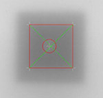
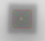
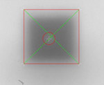
Different techniques and phantoms have been used to investigate the accuracy and stability of various treatment platforms. For the film-based Winston–Lutz test, a film holder is mounted to the gantry head and rotates together with the gantry. At each gantry angle, a piece of film is clamped into the film holder and irradiated perpendicular to the photon beam. For the MRIdian Linac, due to the ring gantry design and inaccessibility of the phantom inside the magnet, we taped films to each side of the phantom before moving the phantom inside the bore. In order to differentiate the radiation fields from opposing directions, two different field sizes were used for anteroposterior/posteroanterior, and Left/Right (L/R) lateral beams. Therefore, two field sizes and one BB image were shown in each film. A smaller field size (1.6 × 1.6 cm2) radiation field was delivered from the anteroposterior and left lateral direction. Our in-house developed Winston–Lutz software automatically located the centers of the BB and the radiation fields [24]. Often due to lack of contrast, the position of the center of the radiation field needed to be manually modified. The positioning accuracy was evaluated by measuring the distance between the center of the BB and the center of the smaller radiation field size. Similarly, the larger radiation field (2.4 × 2.4 cm2) was used in the analysis for the posteroanterior and right lateral beams. The MUs delivered for the small field irradiations was double that of the MUs for the larger fields in order to distinguish the edges of the different fields. The field orientation, field sizes, and delivered MU are summarized in Table 1.
Table 1.
The quantification of the radiation isocenter accuracy by segmenting the BB and field aperture in films acquired at Gantry 0°, 180°, 90°, 270°.
| G: 0 | FS: 16 mm | MU: 2011 | G: 180 | FS: 24 mm | MU: 1013 | G: 90 | FS: 24 mm | MU: 995 | G: 270 | FS: 16 mm | MU: 1986 |
|---|---|---|---|---|---|---|---|---|---|---|---|
 |
 |
 |
 |
||||||||
| Y (S-I) Shift (mm): | 0.61 | Y (S-I) Shift (mm): | 0.85 | Y (S-I) Shift (mm): | 0.87 | Y (S-I) Shift (mm): | 0.68 | ||||
| X (L-R) Shift (mm): | −0.25 | X (L-R) Shift (mm): | −0.42 | Z (A-P) Shift (mm): | −0.24 | Z (A-P) Shift (mm): | 0.19 | ||||
Abbreviations: G, Gantry; FS, Field Size; A, Anterior; P, Posterior; I, Inferior; S, Superior; L, Left; R, Right;
Multiple brain metastases treatment
Patient selection and treatment planning
A retrospective study of five patients previously treated with 2–3 brain metastases was conducted to evaluate treatment plan quality and dose delivery accuracy. The patients were scanned on a CT simulator with a 1 mm slice thickness in the treatment position. Pre- and post-contrast enhanced T1 weighted MR images were fused to the CT images for target delineation. Table 2 lists the number of lesions and volume size for each patient. The average target volume was 4.82 cm3 (range: 0.06–10.95 cm3).
Table 2.
The lesion sizes, number of beams, beam-on time, plan evaluation parameters and patient quality assurance for five patients. Plan evaluation parameters include CI, HI, GI, PCI, and mean dose to normal brain as well as volume of normal brain that received 4, 6, 8, 10 and 12 Gy (V4, V6, V8, V10 and V12). The plan verification includes the percentage difference of point dose measurement, which was measured in the highest dose region within the tumor, and the gamma passing rate and mean value using 3%/1 mm criteria.
| Patient # | Lesion | Lesion Size (cc) | Beam # | Beam on time (min) | CI | HI | GI | PCI | Normal Brain Mean Dose (Gy) | V4 (cc) | V6 (cc) | V8 (cc) | V10 (cc) | V12 (cc) | Point Dose Difference (%) | Gamma Passing Rate (%) | Mean γ Value |
|---|---|---|---|---|---|---|---|---|---|---|---|---|---|---|---|---|---|
| 1 | Rt Temporal | 8.22 | 10 | 11.59 | 1.12 | 1.40 | 4.12 | 0.84 | 1.78 | 132.43 | 66.39 | 41.24 | 27.43 | 19.20 | −3.50 | 98.59 | 0.338 |
| Rt Parietal | 4.38 | 1.25 | 1.42 | 96.97 | 0.325 | ||||||||||||
| 2 | Cerebellum | 6.33 | 11 | 13.57 | 1.16 | 1.18 | 4.44 | 0.81 | 1.88 | 200.98 | 121.97 | 56.35 | 27.11 | 16.05 | 0.36 | 97.33 | 0.300 |
| Lt Temporal | 8.72 | 1.17 | 1.19 | 98.00 | 0.371 | ||||||||||||
| 3 | Lt Ant Cerebellum | 1.21 | 12 | 7.81 | 1.02 | 1.21 | 7.69 | 0.75 | 0.5 | 31.57 | 18.27 | 11.42 | 7.58 | 5.36 | −2.80 | 96.44 | 0.313 |
| Lt Post Cerebellum | 0.06 | 1.83 | 1.11 | 93.50 | 0.431 | ||||||||||||
| 4 | Lt Temporal | 1.07 | 14 | 7.08 | 1.36 | 1.19 | 5.86 | 0.82 | 1.77 | 148.29 | 84.43 | 57.68 | 43.12 | 33.41 | 0.79 | 99.00 | 0.432 |
| Rt Temporal | 0.36 | 1.39 | 1.17 | 95.73 | 0.369 | ||||||||||||
| Lt Cerebellum | 10.95 | 1.02 | 1.15 | 97.57 | 0.374 | ||||||||||||
| 5 | Rt Frontal | 3.80 | 9 | 6.75 | 1.26 | 1.18 | 4.82 | 0.79 | 2.39 | 225.39 | 94.39 | 55.58 | 37.56 | 27.62 | −0.76 | 95.80 | 0.345 |
| Rt Corpus Callosum | 8.05 | 1.27 | 1.18 | 96.61 | 0.334 |
Treatment plans were calculated on the CT images in the View-Ray planning system using the 6 MV FFF beam with a fixed dose rate of 600 MU/min. The isocenter was placed at the geometric center between the lesions within each plan. 10–15 step-and-shoot IMRT beams were used for treatment planning. Plans were prescribed so that 99% of the target volume received the prescription dose, either 16 or 18 Gy, in a single fraction. All plans were calculated in dose to water with 1 mm dose grid size and 1% dose uncertainty. The plan quality was evaluated based on five indices: Radiation Therapy Oncology Group Conformity Index (CI) [20], Paddick Conformity Index (PCI) [13], Gradient Index (GI) [13], and Homogeneity Index (HI) as well as dose to the normal brain. The CI is defined as the ratio of the volume of the prescription dose over the tumor volume. The PCI is defined as the square of the overlap of the tumor volume and prescription isodose volume divided by the product of the tumor volume and the prescription isodose volume. The GI is used to measure the dose drop off and defined as the ratio of the volume of the 50% prescription isodose to that of the 100% prescription isodose line. The HI is calculated by the ratio of the maximum dose within the PTV over the prescription dose. At our institution, it has been our policy to use no margin expansions for target volumes (GTV = CTV = PTV) in SRS cases [9]. The volume of normal brain, defined as the total brain volume minus the PTV, that received 4, 6, 8, 10 and 12 Gy (V4, V6, V8, V10 and V12) and the average dose to the normal brain were also included to evaluate the dose to normal tissue.
Dosimetric verification
All patient plans were mapped onto a 30 × 30 × 15 cm3 solid water phantom (Gammex, Middleton, WI) and recalculated using the same dose calculation settings. An Exradin A26 MR compatible ion chamber with 0.015 cm3 collecting volume (Standard Imaging Inc, Middleton, Wisconsin) was placed at the center of the phantom to measure the absolute dose. The center of the phantom was aligned to the center of one of the lesions for each patient. Coronal planar dose distributions were measured through the midpoint of each lesion with Gafchromic™ EBT3 films to evaluate dose distributions for each lesion. Optical density of the film was converted to dose using a calibration curve determined through polynomial fitting of OD values to a set of known dose values [24]. The gamma index with passing criteria of 3% local dose difference and 1 mm distance to agreement with a 10% cut-off percentage was used to compare the measured dose planes to those calculated in and exported from the treatment planning system and was evaluated using an in-house developed analysis software.
Results
Table 1 summarizes the offsets of the BB relative to the MLC apertures in the Anterior/Posterior (A/P), Superior/Inferior (S/I) and Left/Right (L/R) directions on the film from each of the four gantry angles for a single phantom run. The targeting accuracy was determined by measuring the distance from the center of the BB to the average radiation center for the 14 end-to-end tests. The residual setup error over the 14 tests was 0.2 ± 0.4, 0.8 ± 0.3, −0.4 ± 0.3 mm in the A/P, S/I and L/R direction, respectively. The vector length of the setup error was 1.0 ± 0.1 mm.
Table 2 lists the plan evaluation parameters for all five patients, including the CI, HI and GI and the mean dose to normal brain as well as the volume of normal brain that received 4, 6, 8, 10 and 12 Gy. The mean and range of the CI, HI, GI, and PCI were 1.26 [1.02–1.83], 1.22 [1.11–1.42], 5.38 [4.12–7.69], and 0.80 [0.750–.84], respectively. These results for CI, PCI, and HI are consistent with published results for other single iso-multi target studies [4,6]. The GI values are generally higher than published values, mainly due to the contribution for Patient 3 (GI = 7.69). Fig. 4 illustrates the 9 and 18 Gy isodose distributions for the left temporal and cerebellum lesions in the axial, coronal and sagittal views for patient 2.
Fig. 4.

Isodose distributions for two lesions in the axial, coronal, and sagittal views of Patient 2. The red cross marker indicates the isocenter position. Both left temporal and cerebellum lesions were contoured in red. The 18 Gy isodose line is shown in blue, and the 9 Gy line in purple.
Table 2 summarizes the ion chamber measurement and gamma analysis evaluated using a 3%/1mm passing criteria for all patients. The average absolute dose difference between the measured dose using the ion chamber and the calculated dose was 1.64 ± 1.90% (range: −3.50%–0.79%), and the mean percentage of points passing the 3%/1mm gamma criteria for film analysis was 96.14% (range: 93.50%–98.59%) over eleven measurements for five clinical cases. The mean gamma value for all measurements was 0.36 (range: 0.30–0.43).
Discussion
We investigated the uncertainties and accuracy in target localization and treatment delivery of the MR-guided Linac. Multiple sources could contribute to the uncertainty of the system including the image registration accuracy, geometric distortion of MR images, congruence between imaging and radiation isocenter, and mechanical stability of the gantry rotation. In our study, since the tungsten BB used for the Winston–Lutz test could also cause geometric distortion, we replaced the Winston–Lutz cube with a homogeneous cube of the same dimension to evaluate the impact of distortion on the image registration. There were no relative errors or deviation of target volumes between the two phantom setups. Since a low field strength MR scanner was used for this system, B0 inhomogeneity and susceptibility artifacts were expected to be much less than for conventional 1.5 T or 3 T scanner. Ginn et al. investigated both 2D and 3D spatial distortion of a 0.35 T scanner using the same image sequence with various field of views [6]. Their results showed that the average distortion was ~0.3 mm within 100 mm of the central axis using a 1.5 mm slice thickness scan. In our study, since the phantom was kept within 100 mm of isocenter, the effect of the spatial distortion at further distances was not included in the analysis of targeting accuracy.
The commonly accepted tolerance for isocenter positioning accuracy in SRS and stereotactic body radiation therapy procedures is 1 mm. To put our results with the MR-linac into context, the setup uncertainty reported on the Gamma Knife® system was on the order of 0.3–1.3 mm [12,17,18]. The accuracy of the Cyberknife® system without respiratory motion was 0.4 ± 0.1 mm [2] for 6D skull tracking and 0.7 ± 0.3 mm for fiducial tracking [29]. On a Linac based SRS system, Kim et al. showed that the localization accuracy was 1.2 ± 0.3 mm using the ExacTrac X-ray image guidance system on a NovalisTx™ Linac [10]. Previous work at our institution investigated the end-to-end localization accuracy of a cone beam CT-guided Linac system and showed an uncertainty of 0.5 ± 0.2 mm with a maximum deviation of 0.9 mm [26]. The overall accuracy of the MR-Linac is comparable to other frameless based SRS systems. This suggests that MR-Linac has sufficient targeting accuracy to be presented as an alternative option to the current existing systems for the treatment of brain lesions.
SRS is playing a vital role in the treatment of multiple intracranial metastases. As the imaging technology and treatment precision have improved on Linac-based SRS treatment modalities, treating multiple targets with a shared isocenter, which is typically located at the geometric center of all the lesions within a single plan [8], has gained significant interest due to its efficiency [5]. Dynamic conformal arc, fixed beam IMRT and volumetric modulated arc therapy (VMAT) are the major delivery techniques used in Linac-based stereotactic radiosurgery. In our study, we proposed a single-isocenter coplanar intensity modulated delivery method for SRS treatment of multiple brain metastases. Coplanar beams were utilized since non-coplanar beams are not feasible for the MRIdian MR-Linac due to the limited open space between the two magnets. Wiggenraad et al. compared the IMRT and dynamic conformal arc techniques and concluded that none of tumor type, size, or shape resulted in a systematic advantage for either technique [27]. The dynamic conformal arc technique is a favored technique due to its straight forward planning and relatively few MUs delivered. However, Raymond et al. compared plan quality for fronto-temporal glioma cases, which are challenging considering their location abutting the optic apparatus, using coplanar and non-coplanar IMRT and VMAT planning techniques [15]. They were able to achieve clinically acceptable plans using all four techniques. Compared to coplanar IMRT beams, VMAT plans needed fewer MUs and shorter delivery time [24]. The non-coplanar IMRT beam arrangement is typically superior in sparing the globe and contralateral OARs, especially for complex shaped targets [19]. In our study, we demonstrated that coplanar IMRT beam arrangements can also achieve adequate target coverage, sharp dose drop off, and low integral dose to normal brain when treating multiple targets with a shared isocenter. Plan quality was comparable to VMAT or dynamic conformal arcs for radiosurgery treatment of multiple cranial lesions with a shared isocenter [8,22]. However, the plan quality for Patient 3 was inferior to VMAT or dynamic conformal arc plans typically used for radiosurgery due to there being a higher than desirable low dose spillage. For this challenging case, the two lesions in the cerebellum were adjacent to each other. These two targets shared MLC leaf pairs resulting in normal brain tissue between the two targets not being blocked by the MLC and exposed to radiation. In a traditional Linac system, this problem could be solved by optimizing couch and collimator angles of treatment beams to reduce the unblocked area between lesions [28]. However, in the currently available MR-Linac, noncoplanar (i.e. couch kicks) delivery is not possible and thus lead to a higher GI. Additionally, it is not possible to modify the collimator angle for the ViewRay system due to the mechanical design of the system. An alternative planning approach that can be explored would be to treat each lesion using a separate isocenter to mitigate this effect. Our study was also limited in the number of metastases that were treated with a shared isocenter since patients with four or more lesions are typically treated with whole brain radiotherapy at our institution. It requires further investigation whether it is clinically acceptable to treat a large number of tumors using a single isocenter.
We performed a systematic evaluation treatment plan quality and delivery accuracy of a new MR-guided Linac system for treating multiple targets with a shared isocenter. While the major focus of MR-guided Linac systems is in treatment sites that experience large motion, the challenges encountered in planning provide a good test of the robustness of the system’s capabilities in treating complex cases even for very stable sites, such as in the brain. The accuracy and plan quality were demonstrated to be comparable to other frameless SRS systems. Today, neurosurgery is undergoing a paradigm shift toward real-time intra-procedural visualization, both for enhancing existing therapies and helping to enable new therapies in the future. MR-guided stereotactic radiosurgery has the potential to become an important supplementary tool for neurosurgeons and radiation oncologists to treat brain metastases and other benign and malignant brain tumors.
Acknowledgement
The study was supported by a Research Scholar Grant, RSG-15-137-01-CCE from the American Cancer Society and partially supported by National Cancer Institute of the NIH: R01CA204189.
Footnotes
Conflict of interest
Drs. Wen, Glide-Hurst, Siddiqui, Movsas and Chetty and Mr. Doemer received speaker honorariums from Viewray Inc. Ms. Bellon and Mr. Victoria are employees of Viewray Inc.
References
- [1].AlDahlawi I, Prasad D, Podgorsak MB. Evaluation of stability of stereotactic space defined by cone-beam CT for the Leksell Gamma Knife Icon. J Appl Clin Med Phys 2017;18:67–72. [DOI] [PMC free article] [PubMed] [Google Scholar]
- [2].Antypas C, Pantelis E. Performance evaluation of a CyberKnife G4 image-guided robotic stereotactic radiosurgery system. Phys Med Biol 2008;53:4697–718. [DOI] [PubMed] [Google Scholar]
- [3].Bohoudi O, Bruynzeel AME, Senan S, et al. Fast and robust online adaptive planning in stereotactic MR-guided adaptive radiation therapy (SMART) for pancreatic cancer. Radiother Oncol 2017;125:439–44. [DOI] [PubMed] [Google Scholar]
- [4].Chojnowski J, Gajewski R. An automatic method of the isocentre position verification for micromultileaf collimator based radiosurgery system. Australas Phys Eng Sci Med/Supported Australas College Phys Sci Med Australas Assoc Phys Sci Med 2011;34:15–21. [DOI] [PubMed] [Google Scholar]
- [5].Clark GM, Popple RA, Young PE, Fiveash JB. Feasibility of single-isocenter volumetric modulated arc radiosurgery for treatment of multiple brain metastases. Int J Radiat Oncol Biol Phys 2010;76:296–302. [DOI] [PubMed] [Google Scholar]
- [6].Ginn JS, Agazaryan N, Cao M, et al. Characterization of spatial distortion in a 0.35 T MRI-guided radiotherapy system. Phys Med Biol 2017;62:4525–40. [DOI] [PMC free article] [PubMed] [Google Scholar]
- [7].Henke L, Kashani R, Robinson C, et al. Phase I trial of stereotactic MR-guided online adaptive radiation therapy (SMART) for the treatment of oligometastatic or unresectable primary malignancies of the abdomen. Radiother Oncol 2018;126:519–26. [DOI] [PubMed] [Google Scholar]
- [8].Huang Y, Chin K, Robbins JR, et al. Radiosurgery of multiple brain metastases with single-isocenter dynamic conformal arcs (SIDCA). Radiother Oncol 2014;112:128–32. [DOI] [PubMed] [Google Scholar]
- [9].Huang Y, Zhao B, Chetty IJ, Brown S, Gordon J, Wen N. Targeting accuracy of image-guided radiosurgery for intracranial lesions: a comparison across multiple linear accelerator platforms. Technol Cancer Res Treat 2016;15:243–8. [DOI] [PubMed] [Google Scholar]
- [10].Kim J, Jin JY, Walls N, et al. Image-guided localization accuracy of stereoscopic planar and volumetric imaging methods for stereotactic radiation surgery and stereotactic body radiation therapy: a phantom study. Int J Radiat Oncol Biol Phys 2011;79:1588–96. [DOI] [PubMed] [Google Scholar]
- [11].Liu SH, Murovic J, Wallach J, et al. CyberKnife radiosurgery for brainstem metastases: management and outcomes and a review of the literature. J Clin Neurosci 2016;25:105–10. [DOI] [PubMed] [Google Scholar]
- [12].Ma L, Pinnaduwage D, McDermott M, Sneed PK. Whole-procedural radiological accuracy for delivering multi-session gamma knife radiosurgery with a relocatable frame system. Technol Cancer Res Treat 2014;13:403–8. [DOI] [PMC free article] [PubMed] [Google Scholar]
- [13].Paddick I, Lippitz B. A simple dose gradient measurement tool to complement the conformity index. J Neurosurg 2006;105(Suppl):194–201. [DOI] [PubMed] [Google Scholar]
- [14].Palacios MA, Bohoudi O, Senan S, Slotman BJ, Bruynzeel AME, Lagerwaard FJ. MR-guided adaptive stereotactic radiotherapy: a new paradigm in radiotherapy. Phys Med 2017;44:1. [DOI] [PubMed] [Google Scholar]
- [15].Panet-Raymond V, Ansbacher W, Zavgorodni S, et al. Coplanar versus noncoplanar intensity-modulated radiation therapy (IMRT) and volumetric-modulated arc therapy (VMAT) treatment planning for fronto-temporal high-grade glioma. J Appl Clin Med Phys 2012;13:3826. [DOI] [PMC free article] [PubMed] [Google Scholar]
- [16].Raaijmakers AJ, Raaymakers BW, Lagendijk JJ. Magnetic-field-induced dose effects in MR-guided radiotherapy systems: dependence on the magnetic field strength. Phys Med Biol 2008;53:909–23. [DOI] [PubMed] [Google Scholar]
- [17].Ruschin M, Nayebi N, Carlsson P, et al. Performance of a novel repositioning head frame for gamma knife perfexion and image-guided linac-based intracranial stereotactic radiotherapy. Int J Radiat Oncol Biol Phys 2010;78:306–13. [DOI] [PubMed] [Google Scholar]
- [18].Schlesinger D, Xu Z, Taylor F, Yen CP, Sheehan J. Interfraction and intrafraction performance of the Gamma Knife Extend system for patient positioning and immobilization. J Neurosurg 2012;117(Suppl):217–24. [DOI] [PubMed] [Google Scholar]
- [19].Sharma SD, Jalali R, Phurailatpam RD, Gupta T. Does intensity-modulated stereotactic radiotherapy achieve superior target conformity than conventional stereotactic radiotherapy in different intracranial tumours? Clin Oncol (R Coll Radiol) 2009;21:408–16. [DOI] [PubMed] [Google Scholar]
- [20].Shaw E, Kline R, Gillin M, et al. Radiation Therapy Oncology Group: radiosurgery quality assurance guidelines. Int J Radiat Oncol Biol Phys 1993;27:1231–9. [DOI] [PubMed] [Google Scholar]
- [21].Skworcow P, Mills JA, Haas OC, Burnham KJ. A new approach to quantify the mechanical and radiation isocentres of radiotherapy treatment machine gantries. Phys Med Biol 2007;52:7109–24. [DOI] [PubMed] [Google Scholar]
- [22].Thomas EM, Popple RA, Wu X, et al. Comparison of plan quality and delivery time between volumetric arc therapy (RapidArc) and Gamma Knife radiosurgery for multiple cranial metastases. Neurosurgery 2014;75:409–17. discussion 417–408. [DOI] [PMC free article] [PubMed] [Google Scholar]
- [23].Treuer H, Hoevels M, Luyken K, et al. On isocentre adjustment and quality control in linear accelerator based radiosurgery with circular collimators and room lasers. Phys Med Biol 2000;45:2331–42. [DOI] [PubMed] [Google Scholar]
- [24].Verbakel WF, Cuijpers JP, Hoffmans D, Bieker M, Slotman BJ, Senan S. Volumetric intensity-modulated arc therapy vs. conventional IMRT in head-and-neck cancer: a comparative planning and dosimetric study. Int J Radiat Oncol Biol Phys 2009;74:252–9. [DOI] [PubMed] [Google Scholar]
- [25].Wen N, Li H, Song K, et al. Characteristics of a novel treatment system for linear accelerator-based stereotactic radiosurgery. J Appl Clin Med Phys 2015;16:5313. [DOI] [PMC free article] [PubMed] [Google Scholar]
- [26].Wen N, Snyder KC, Scheib SG, et al. Technical Note: Evaluation of the systematic accuracy of a frameless, multiple image modality guided, linear accelerator based stereotactic radiosurgery system. Med Phys 2016;43:2527. [DOI] [PubMed] [Google Scholar]
- [27].Wiggenraad RG, Petoukhova AL, van Versluis L, Santvoort JP. Stereotactic radiotherapy of intracranial tumors: a comparison of intensity-modulated radiotherapy and dynamic conformal arc. Int J Radiat Oncol Biol Phys 2009;74:1018–26. [DOI] [PubMed] [Google Scholar]
- [28].Wu Q, Snyder KC, Liu C, et al. Optimization of treatment geometry to reduce normal brain dose in radiosurgery of multiple brain metastases with single-isocenter volumetric modulated arc therapy. Sci Rep 2016;6:34511. [DOI] [PMC free article] [PubMed] [Google Scholar]
- [29].Yu C, Main W, Taylor D, Kuduvalli G, Apuzzo ML, Adler JR Jr. An anthropomorphic phantom study of the accuracy of Cyberknife spinal radiosurgery. Neurosurgery 2004;55:1138–49. [DOI] [PubMed] [Google Scholar]