Abstract
Obese patients challenge imaging departments in their ability to obtain diagnostic quality images and to perform image-guided interventions. These technical challenges include properly accommodating large patients on imaging equipment, adjusting equipment settings to address imaging limitations, and pre-planning and preparation for image-guided interventions to insure safe and successful outcomes. Knowing and addressing these challenges can result in successfully addressing the imaging and image-guided interventions needs of obese patients.
Impact of Obesity on Imaging in General and Historical Impact over the Years
Imaging plays a central role in the diagnosis and management of many medical conditions. With advances in technology and the expanded availability of imaging equipment in emergency rooms and outpatient clinic centers, use of imaging to diagnose many medical conditions has grown over the past 10 years.
Critical to the success of medical imaging to diagnose a condition, is the ability to obtain diagnostic quality images. In the obese population, the ability to get diagnostic quality images and the ability to perform image-guided interventions can be technically challenging. These challenges have been identified in the literature.1–10 As the prevalence of obesity has increased in the USA, there have been increased challenges in interpreting images due to imaging limitations posed by obese patients. A study published in 2006 showed that over a course of a 15-year period (1999–2003), there was an increased use of the words “limited by body habitus” by radiologists attempting to interpret limited quality images obtained on obese patients.1 These limitations are a result of attenuation of the X-ray and ultrasound beams, increased noise, and resultant artifacts. The purpose of this article is to review the technical challenges of medical imaging and image-guided interventions in the obese population and review advances made in the past 10 years.
Imaging Obese Patients
Clinically, obesity is classified by body mass index, which accounts for both height and weight and defined as kg m–2.11, 12 Although body mass index has been clinically useful to quantify the degree of obesity and classify patients into categories for diagnosis and treatment for the purposes of medical imaging, the most important factors to obtain diagnostic quality imaging include patient weight, patient girth, and distribution of the adipose tissue.2
For all imaging equipment available, there are industry standard defined table weight and aperture limits.2 Recent technological advances allow for improving image quality without increasing radiation dosage.8 Before obtaining any medical imaging in obese patients, it is critical to confirm that the patient can be accommodated on the imaging equipment. At Massachusetts General Hospital, it is now standard practice to post table weight and aperture limits on CT and MRI equipment (Figure 1). These limits can be incorporated into radiology order entry software so that alerts can be generated when the medical image study is ordered on patients whose documented weight exceeds the provided limits of the imaging equipment.
Figure 1.
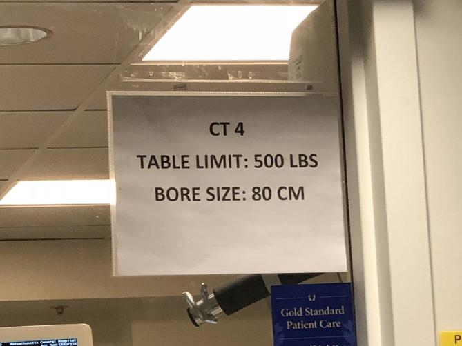
Photograph in the control room of one of our CT suites showing the posted sign detailing maximum table weight and gantry diameter.
Accommodating Patients
For all cross-sectional imaging equipment, there are industry standard table weight and aperture limits. In a 2008 survey of United States hospitals, only 28% of academic hospitals and 10% of non-academic hospitals had CT scanners in the emergency department that could accommodate obese patients.6, 10 Over the past 10 years, these limits have been increased by manufacturers in attempts to accommodate the bariatric population (Table 1). Of all the cross-sectional imaging equipment typically available in hospitals, CT scanners tend to have the largest table weight and aperture limits and are, therefore, the most useful tool to accommodate and image larger patients.
Table 1.
Maximum table weight and aperture limits for currently available bariatric imaging equipment
| Imaging modality | Weight limits (kg) | Maximum aperture opening (cm) | Maximum field of view (cm) |
| Fluoroscopy | 317.5 | 117 | N/A |
| CT | 308.4 | 85 | 65 cm |
| MRI | 249.5 | 70 | Virtual field of view 205 cm |
| Open MRI | 249.5 | 55 |
It is important for all hospitals and outpatient centers to document patient weight and girth diameter in the patient's health record to ensure that they will fit on the imaging equipment available at their institution. Patients who exceed the weight limit of the equipment defined by the manufacturer can potentially damage the mechanics of the equipment. Failure to accommodate patients on medical imaging can be embarrassing for the patient, their family, and can disrupt the throughput of busy inpatient or outpatient imaging centers.
Table weight limits
CT
Industry standard table weight limits for CT is usually 450 Ibs (205 kg). Newer larger CT scanners are currently available which can accommodate patients weighing up to 680 Ibs (308.4 kg). These table weight limits exist because the table movement mechanics can be limited by the weight of the patient. For some CT manufacturers, it is possible to exchange the standard CT table accommodating up to 500 Ibs with a bariatric table that can accommodate up to 676 Ibs. The bariatric tables have less padding and have a flat (non-curved surface).9
MRI
Industry standard table weight limit for MRI is usually 350 Ibs (159 kg). For MRI, more than the table weight limit, typically the bore diameter is the limiting factor. The typical MRI bore length is typically longer than the gantry length of a CT scanner and patients can become claustrophobic laying inside a long MRI bore.
Fluoroscopy
Table weight limit for traditional fluoroscopic/angiographic equipment is typically 450 Ibs (205 kg). Table weight limits for fluoroscopic/angiographic equipment exist not because of the table motor but the ability of the table to accommodate the patient. Table width is also a problem in large patients as some patients and fluoroscopy operators may feel table is too narrow for the body diameter. Standard table width is 45 cm.9 The ability to turn patients LPO (left posterior oblique) and RPO (right posterior oblique) may be hindered if there is a perception that the table width is too narrow to safely accommodate the patient.
Aperture openings
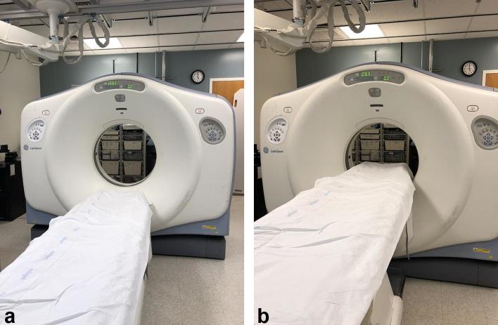
Even though patients may be able to fit on imaging equipment from a weight standpoint, a second critical consideration is the ability to accommodate the patient through the imaging equipment aperture. For cross-sectional imaging, the widest section of the aperture is the horizontal diameter. Although the vertical diameter is typically the same as the horizontal diameter (the gantry or bore is typically circular in shape), the vertical diameter is often smaller as one has to account for the entry of the table into the gantry or bore which excludes approximately 18 cm from the vertical dimension (Figure 2). Often, it is hard to objectively quantify patient girth. It is common for many hospitals and outpatient clinics to measure patients’ weight. It is not common that body diameter is measured. In addition, body diameter can change based on the patient's position. One unique solution identified is to create a hula hoop in the dimension of the largest CT scanner in the institution and have it available to check the diameter of a patient who could potentially exceed the aperture limit based on their weight approaching the weight limit of the table. Typically, if patients barely fit into the aperture opening, they are “squeezed” in—body straps from the CT/MRI table can be used to help fit patients into the aperture opening. However, unfortunately these solutions occasionally place the ability to make a clinical diagnosis at odds with patient tolerability and comfort.
Figure 2.
Two photographs of the same CT scanner showing loss in the length of the vertical gantry opening diameter when the table is positioned within the gantry space. (a) Photograph of CT scanner with table positioned outside the gantry and thereby accommodating a vertical length gantry diameter of 70 cm. (b) Photograph of CT scanner with table now positioned inside the gantry, showing decreased in the vertical length gantry diameter by 18 cm—vertical diameter is now only 52 cm.
CT
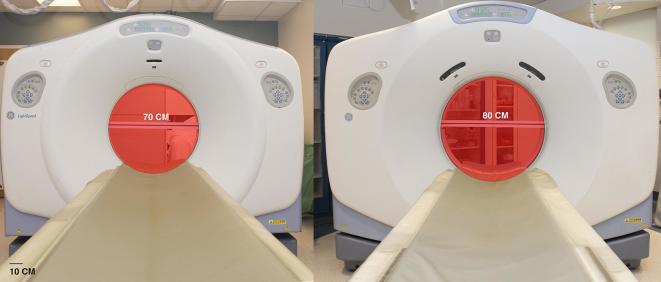
Typical industry standard gantry diameter is 70 cm. The larger bariatric CT scanners have a gantry diameter measuring up to 85 cm in diameter (Figure 3). There are CT scanners in Radiation Oncology Department that have 90 cm gantry diameter but they are not suitable for diagnostic imaging.10
Figure 3.
Photograph of two CT scanners showing the differences in gantry opening size. Left photograph—standard CT with 70 cm diameter gantry opening. Right photograph—large bore CT with 80 cm gantry opening.
MRI
For many years, MRI bore diameter was 60 cm. The 60 cm diameter does not account for the placement of phased array coils, which are typically placed on top of the patient to improve image quality. Excluding surface coils to help accommodate patients in the MRI bore can result in suboptimal image quality. Patients who are “squeezed” into a bore can sustain minor burns in areas where the skin touches inner lining of the bore. Use of pillows placed between the patient and the bore can prevent these minor burns. Another issue is bore length. Due to issues of claustrophobia, shorter bore lengths that allow a greater portion of the body to be out of the bore are better tolerated by patients, however, this configuration comes at the expense of coverage along the Z direction.
A typical scenario in hospitals in the USA is as follows: a patient is referred for MRI. The patient cannot fit onto any hospital MRI. They are then referred to outpatient “Open MRI” units that have a larger aperture opening but are typically of lower field strength (0.3–1.0 T) and therefore, lower image quality, compared to closed bore higher field strength MRI units.
Over the past 10 years, equipment manufacturers have increased diameters of closed bore MRIs to 70 cm.
Fluoroscopy
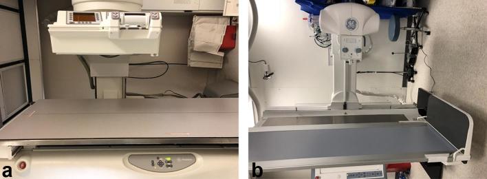
Aperture openings for fluoroscopic equipment have increased dramatically due to the special role fluoroscopic equipment plays in the post-procedural evaluation of bariatric surgery patients. With the rapid rise in the use of bariatric surgery as a treatment option for morbid obesity, it has been increasingly important to have imaging equipment that can accommodate large patients for their post-operative evaluation. Imaging centers that perform bariatric surgeries are now required to have fluoroscopic equipment that can accommodate large patients with large girths in the immediate post-operative period. Manufacturers have dramatically increased the aperture openings. One technical solution by manufacturers that has allowed increase in aperture openings is to invert the film panel and image intensifier (Figure 4). With this adjustment, the maximum aperture opening in now 117 cm. This solution, however, comes at a cost of increased radiation doses to the radiologists/radiographers and often these studies are done with the movement of the table and machine remotely behind leaded glass panel.
Figure 4.
Photographs of two fluoroscopic imaging equipment showing differences in aperture opening. (a) Standard fluoroscopic machine with 45 cm aperture opening. (b) Bariatric fluoroscopic machine with 63 cm aperture opening. The larger opening is possible as the image intensifier and film capture plate have been inverted.
Radiography X-ray cassette film size
An occasionally overlooked issue is accounting for limitations of a fixed cassette film size. For plain radiographs, imaging the chest or abdomen can be challenging if patients exceed the size of standard 14 × 17 inch film cassette size (Figure 5). Knowing this limitation is important for radiographers. For adequate imaging of the area of interest, knowledge of the patient’s size and additional planning to image using multiple overlapping cassettes to cover the entire anatomy may be essential. Use and knowledge of anatomical landmarks such as the bend of patient’s elbow approximating the iliac crest, can help radiographers properly obtain radiographs in obese patients.9
Figure 5.
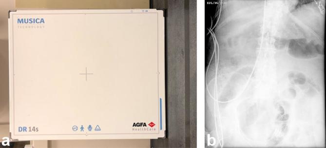
(a) Photograph showing standard 14 × 17 inch film cassette size. A single 14 × 17 inch cassette size in larger patient may not cover entire area. (b) Abdominal X-ray image in a 73-year-old male showing that only a portion of his large abdomen is images and, therefore, potential risk for missing crucial pathology.
Ultrasound
One advantage of sonography compared to cross-sectional imaging and fluoroscopy is that there is no table weight or aperture opening limit. Ultrasound exams can be performed at the patient's bedside. However, as detailed below, imaging quality can be compromised with sonography of obese patients.
IMAGE quality in obese patients: challenges and solutions
Once patients are accommodated onto imaging equipment, the next issue to address is the ability to get diagnostic quality images. There are technical challenges to obtaining diagnostic quality images in obese patients. These challenges stem from the thick adipose tissue, the X-rays and ultrasound beams have to penetrate through. Not only is there attenuation of these beams, but the increased distance of penetration result in motion artifact as well as increased scatter.
Ultrasound
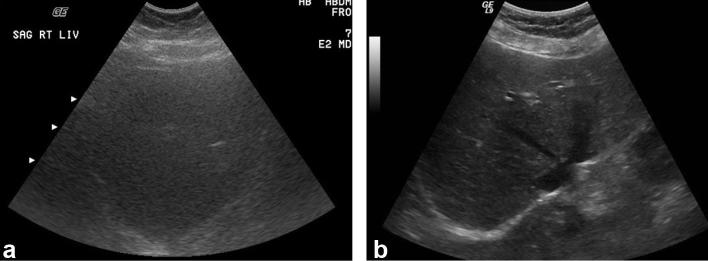
Ultrasound beams are directly attenuated by fat which limits the image quality. Sound waves from ultrasound are estimated to be attenuated at a rate of 0.63 dB per centimeter of fat.2 Limitations in image quality start to become evident in patients who weigh 250 to 300 Ibs (Figure 6). Because thickness of tissue has a direct impact on ultrasound image quality, the distribution of adipose tissue is critical to the success of the ultrasound exam. A 350 Ibs patient with distribution of fat predominately in the subcutaneous tissues will have lower quality images as the ultrasound beam has to penetrate through the thickness of subcutaneous adipose tissue just to image the internal organs (Figure 7). A patient of similar weight with distribution of fat predominately in the intraperitoneal compartment will not have much skin to organ thickness to penetrate through and, therefore, will have better ultrasound image quality of the internal organs.
Figure 6.
Comparison of image quality of two liver ultrasound exams in two different-sized patients. (a) Ultrasound examination of the liver in a 350 Ibs patient shows limited visibility of the hepatic structures—bile ducts and vessels not well seen due to attenuation of the sound waves by thickness of subcutaneous tissue. (b) Abdominal ultrasound in 150 Ibs patient showing normal hepatic parenchyma with good visualization of bile ducts and vessels.
Figure 7.
Axial CT scans of the abdomen in two patients showing how the distribution of fat can impact hepatic ultrasound image quality. (a) Axial CT image in an obese patient with predominately subcutaneous fat. Any potential ultrasound exam in this patient requires the ultrasound beam to penetrate through the 7 cm of subcutaneous fat to image the liver and therefore limits ultrasound image quality (b) Axial CT image in another non-obese patient shows less subcutaneous fat, therefore, ultrasound exam of the liver in this patient will not be limited due to fat.
Solutions to address technical challenges in obtaining diagnostic quality ultrasound images include: using the lowest frequency (1.5–2 MHz) transducer (to maximize of penetration of depth), pushing in with the transducer to decrease the depth of adipose tissue to penetrate through, and placing the transducer at its closest distance to the organ of interest.
In addition, various manufacturers have varying quality transducers and ultrasound machines. Sometimes, using a different ultrasound machine may yield improved image quality. Using the harmonics setting has also been reported to improve image quality in obese patients.13 Harmonics imaging depend on the detection of signals from reverberating soft tissues. Therefore, in patients with greater amounts of soft tissue, the signal-to-noise ratio, contrast and spatial resolution can be improved by using harmonics. Despite these adjustments, if ultrasound is unable to obtain diagnostic quality images, it is always possible to consider other modalities such as nuclear medicine hepatobiliary (HIDA) scan to diagnose acute cholecystitis or CT may be obtained to aid in diagnosis.
CT
Typically, if the patient can fit on the CT scanner, diagnostic quality images can be obtained. Challenges in obtaining diagnostic quality images in CT include attenuation of the X-ray beams due to excessive soft tissue and increased imaging time resulting in patient motion artifact.
CT artifacts
CT—Increased noise/quantum mottle
Attenuation of the photon beams due to obesity results in increased noise. Solutions to address the technical challenges in obtaining diagnostic quality CT images include changing fixed mAs setting to “automatic” mAs, increasing the kVP, and decreasing gantry rotation speed (effectively increasing mAs) (Table 2). Increasing the voltage to 140 kVP improves penetration and decreases noise, however, it also decreases image contrast.
Table 2.
CT protocol for standard patients compared to obese patients (>350 Ibs)
| CT setting | Standard setting | Obese patient |
| kVP | 120 | 140 |
| mAs | “Fixed mAs” | “Automatic mAs” |
| Gantry rotation speed per rotation | 0.5 s | 1 s |
| Pitch | 1.1 | 0.6 |
CT—motion artifact
Increased soft tissue thickness leads to additional time for photons to penetrate through the body and can result in motion artifact. The impact of motion artifact on CT is less dramatic than on plain radiographs, however, it can be seen as indistinctness of the margins of solid organs.
CT—beam hardening/truncation artifact
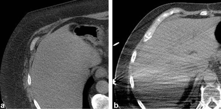
Most CT scanners have a field of view of 50 cm. Portions of the patient's anatomy that extends beyond the field of view can result in beam hardening artifact, which is seen as a bright line causing streak artifact in the adjacent tissues (Figure 8). Special bariatric scanners have an extended field of view(eFOV) of up to 85 cm. The eFOVs are reconstructed CT images from a partial data set. Although the eFOV were designed to accommodate larger patients, it can also result in image distortion.14
Figure 8.
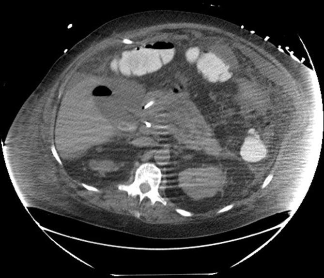
Axial abdominal CT scan in a 76-year-old obese patient shows many of the limitations and artifacts seen in obese patients—quantum mottle (increased noise), beam hardening artifact (bright area in large area of left flank and smaller area posterior right flank where patient’s body goes beyond the field of view), ring artifact, and motion artifact (indistinct edge of the kidneys).
Beam hardening or truncation artifact occurs when portions of the patient’s anatomy extend outside the field of view and reconstruction algorithms assume that the attenuation was within the field of view and, therefore, generate a band of higher (bright) attenuation (Figure 8).3, 10 This can be addressed by extending the field of view (more easily achieved with the bariatric CT scanners) to cover the patient’s entire cross-sectional anatomy or by adjusting the patient’s anatomy so that the area of interest does not suffer this artifact.
CT—inappropriate image cropping
In obese patients who exceed the field of view are at risk of having their images cropped by radiologist/technologist concentrating on internal organ structures. Crucial anatomy and pathology can be cropped out of an image due to extension beyond the field of view or when the images are manually cropped by the technologists.3, 10
CT—ring artifact
Ring artifacts occur when there are errors in detector calibration. In the normal population, ring artifacts are usually not detectable because there are enough photons and there are no issues with image noise. However, in the obese population, ring artifacts are exaggerated and seen due to increase in image noise.10 They are seen as ring-shaped distortion in the center of the image and can obscure crucial central anatomical abnormalities (Figure 8). Ring artifacts can be addressed by increasing the kVP and mAs.
Possible benefits of obesity for CT
Typically, if patients can fit on CT scanners and diagnostic quality images can be obtained, the image from patients with large amount of intraperitoneal fat are typically easier to interpret due to the separation of internal structures by the fat.
Recent advances in CT that impact limitations of obesity
Over the past 5 years, there have been advances in CT technology that indirectly have addressed challenges related to obesity including image quality and radiation dose. These advances include proliferation of dual source CT scanners and improvement in post-processing techniques including iterative reconstruction
Dual source CT
Recent proliferation of dual source scanners offers the potential for improving image quality because of higher X-ray tube power (80 kW from two sources provides a total power output of 160 kW).3
Iterative reconstruction
For many years, conventional image reconstruction was accomplished via back filtered production. Newer iterative reconstruction algorithms allow reconstruction of image using statistical modeling which decrease noise without decreasing image resolution. Using iterative reconstruction allows for imaging obese patients at lower radiation doses without sacrificing image quality.8,10,15–17 A recent paper of five abdominal/pelvic CT protocols across three scanners showed that use of iterative reconstruction could achieve 30–60% lower radiation doses while maintaining image quality.16
Radiation dose
Increasing the mAs and kVP to obtain better quality images for CT, fluoroscopy, and plain radiographs comes at a cost of increasing radiation dose to obese patients. One study showed that the entrance site radiation can be 10 times higher in obese patients compared to non-obese patients.18 However, CT phantom studies have shown that the radiation dose to internal organs is decreased in obese patients because fat can attenuate the radiation beam.19A recent paper summarized that for CT examinations of the abdomen, the typical increased dose in obese patient is approximately times that of a normal patient20
Plain radiographs/fluoroscopy
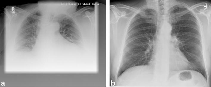
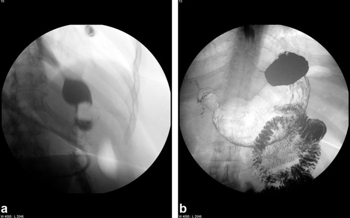
For both plain radiographs (Figure 9) and fluoroscopy (Figure 10), technical challenges in imaging obese patients include attenuation of the X-ray beam resulting in increased noise and increased motion artifact due to the increased exposure time necessary.
Figure 9.
Comparison of chest radiographs in obese and normal patient. (a) Limited chest radiograph due to inadequate photon penetration resulting in increased nose, and motion artifact. (b) Compare to a chest radiograph in normal sized male patient.
Figure 10.
Frontal view fluoroscopic images of an upper gastrointestinal study from (a) standard fluoroscopic machine with poor contrast and motion artifact and (b) special bariatric fluoroscopy machine. The bariatric fluoroscopic machine accommodates a larger patient and with increases in kVP, to deliver clearer images.
Solutions to address these challenges including increasing the mAs and kVP, but this comes at the cost of increasing radiation dose to the patient.21
For plain radiographs using a bucky grid can decrease scatter which can improve image quality and decrease radiation dose to the patient and radiographer. Post-acquisition adjustments can also improve image quality including doing a double exposure, increasing the film development speed, adjusting the window and level settings.
Limitations for fluoroscopy
If the patient is unable to undergo fluoroscopic evaluation due to the table weight limit it may be possible, although less optimal, to perform a study with overhead radiographs only. Another option may be to transfer the patient to CT, as the allowed weight limit may be greater.
Radiation dose
Increases in radiation doses occur due to increases in mAs and kVP to penetrate through the soft tissue. Effective dose of radiographs in extremely obese can exceed 100 mSv.22 A recent paper summarized the increased dose in typical abdominal imaging for obese patients compared to standard sized patients as 10 times more for radiographs and 5 times more for fluoroscopic exams20 Unlike CT, there is no iterative reconstruction that can improve or maintain image quality at lower radiation doses. There are, however, techniques to decrease radiation doses in obese patients. including: positioning patient so that the thinnest body fat layer is closest to the image receptor, and increasing the tube voltage.22
MRI
Once the patient can be accommodated on MR equipment, diagnostic quality images can typically be obtained. For obese patients, whose bodies approach the inner lining of the MRI bore, there is an increased potential for claustrophobia. Solutions include placing the patient feet first, administering anxiolytics, or limiting exam times can ensure a complete study.
MRI—signal to noise ratio
MRI images can be limited due to the attenuation of the RF beam by fat. Although the degree of attenuation is not as great as photons in X-ray beams or sound waves in sonography, the signal to noise ratio of the image can be affected. Solutions to address this include increasing the field strength of the MR scanner which can lead to higher signal to noise ratios.3
MRI field of view
Another technical challenge for MRI of obese patients includes the limited field of view. Standard field of view for a 1.5 T MRI is 40–50 cm. Patient's anatomy that exceed the field of view can cause wraparound artifact (Figure 11). Solutions to address this include increasing the field of view if possible, choosing “no wrap” option, adjusting the configuration of the field of view from a rectangular configuration to a square configuration.3 Newer MRI scanners that uses matrix coils and moving table options, allow for the creation of a virtually eFOV. However, this eFOV benefits the z-axis and is used for MR angiography.23
Figure 11.
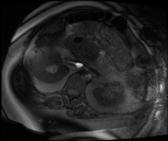
Axial T1 MRI in an obese patient showing wrap around artifact. Images of the anterior pelvis exceeding the field of view are projected along the posterior anatomy. There is also inadequate fat saturation with bands of high signal.
Nuclear medicine/positron emission tomography-CT
Technical challenges of nuclear medicine and especially positron emission tomography-CT include limitations in the amount of weight-based nuclear medicine agents that can be administered in obese patients. Obese patients who exceed the limits often have a lower dose in their body and as these photons exit the body, they are attenuated by be adipose tissue. Solutions to address these issues include providing the maximum dosage allowable in obese patients and increasing gamma camera imaging times to maximize photon counts.
Mammography
Mammograms can potentially benefit from large amounts of adipose tissue separating mammary tissue. However, as with fluoroscopy and plain radiographs, the X-ray beam can be attenuated by the adipose tissue. Attenuation results in increased noise, decreased image contrast, and motion unsharpness.24–26 Larger breasts are also harder to compress and have been correlated with increased rates of recall and false-positive screening mammograms.25, 26
OTHER LOGISTICAL ISSUES
Starting an intravenous (i.v.) line
When an obese patient arrives for imaging, it is important to establish whether i.v. access is in place. Obtaining i.v. access in obese patients can be challenging due to the soft-tissue thickness. Solutions to improve success of obtaining i.v. access in obese patients includes using multiple tourniquets, displacing adipose tissue, using anatomical landmarks and warm compresses3, 27
Intravenous contrast dose
Intravenous contrast doses for CT and MRI are weight-based and calculated based on cm3 kg–1. Obese patients whose weight exceed the maximum doses may not be getting adequate contrast to opacify internal organs. Solutions to improve vascular opacification in obese patients include using larger cannula 18-gauge venous lines and placing access into more central larger caliber veins. These steps will allow for higher injection rates and decrease the probability of subcutaneous extravasation of contrast material.10
IMAGE-GUIDED INTERVENTIONS
Performing image-guided interventional procedures in obese patients can present its own technical challenges independent of the imaging portion of the interventions.2, 28,29 These challenges include adequately visualizing targeted areas, inadequate instrument/equipment length, ability of the instruments and large patient to fit into CT and MRI scanners, radiation doses in interventional radiology procedures, safely sedating obese patients, post-procedure recovery and healing.
Adequately visualizing targets
Ultrasound is used for many interventional procedures such as focal biopsies and drainages. Multiple studies have evaluated the limitations of performing ultrasound procedures in obese patients.29–31 Poor sonographic visualization can potentially lead to non-diagnostic specimens and higher rates of complications.29 Solutions to address this include performing transjugular non focal kidney30 or liver biopsy instead of percutaneous biopsies or positional changes such as placing patients for non-focal renal biopsies in a supine position and approaching the kidney from an anterolateral approach31
Instrument length
All wires and catheters used for interventional procedures are manufactured at standard lengths. The longest needles and catheters measure up to 25 cm. Technical challenges include:
Accessing femoral arteries and veins which can be obscured by adipose tissue limiting access via ultrasound or use of typical landmarks. There are devices that try to address this issue by using straps that hold the pannus out of the way.
-
Patient’s exceeding lengths of the longest needle/catheters. Critical to the success of the successful image-guided interventional procedure in obese patients is pre-procedural planning by reviewing the imaging to identify the shortest distance from the skin entrance site to the target. Occasionally, changing the patient position and displacing the subcutaneous adipose tissue by pushing instruments into the skin can allow one to reach target previously deemed not possible.
Although many catheters are 25 cm in length, the critical distance is the length between the skin and the pigtail. These distances can be less than 25 cm (Figure 12) and, therefore, becomes a serious limitation in obese patients.
Ability to fit patient and long instruments into the CT gantry (Figure 13). This is an often overlooked issue that comes up once it is time to obtain images in an interventional procedural case. If the long instrument is only placed a few centimeters into the skin to minimize internal organ damage it may not fit into the gantry with the large patient. Solutions to address this include using a smaller needle to correctly confirm skin entrance site and trajectory and then using tandem trocar technique to place the longer needle in relation to the shorter needle. Another solution is using flexible instruments made by some manufacturers that can be bent outside the patient to clear the gantry for imaging.
Figure 12.
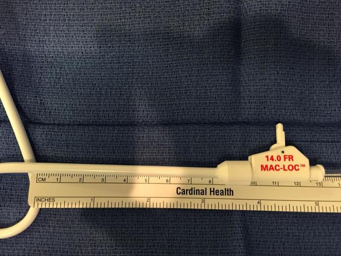
Photographs of standard gastrostomy tube. Although catheters can be up to 25 cm in length, the distance from the hub to the pigtail can be the most critical distance. In this picture, this distance is 8 cm and, therefore, cannot accommodate a patient who has skin to stomach thickness greater than 8 cm.
Figure 13.
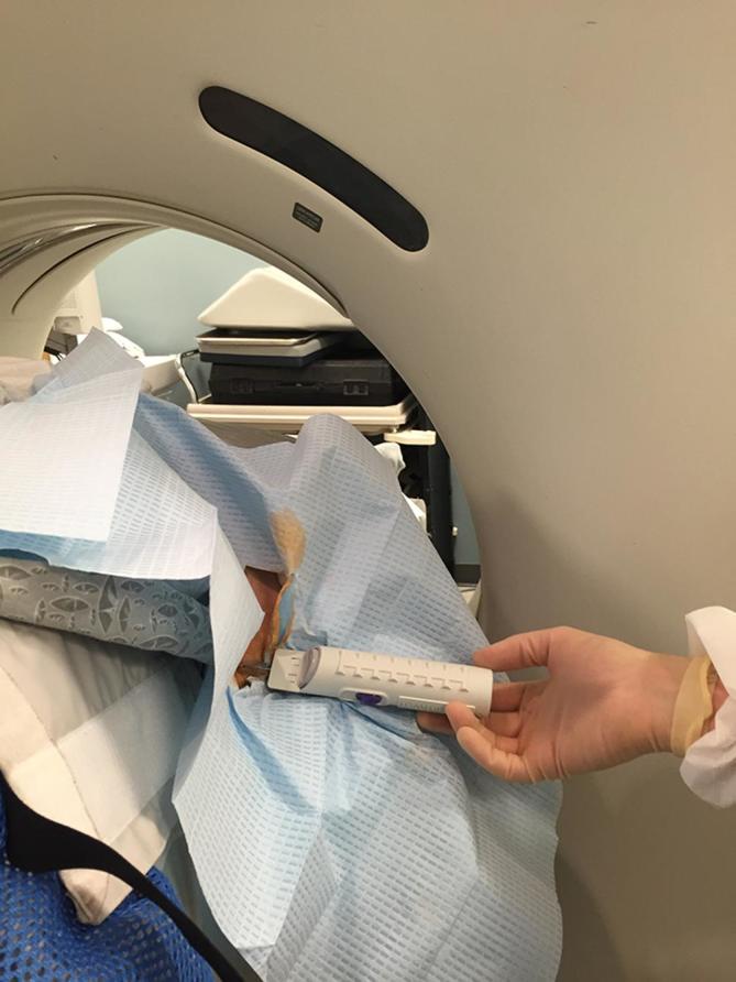
Photograph of the CT-guided procedure showing potential for the biopsy needle to not fit into the CT gantry.
Interventional radiology radiation dose
Angiographic equipment can often deliver larger radiation doses during long/challenging angiographic cases which can occasionally exceed safety thresholds set by the Radiation Safety Office of the institution. At our institution, for interventional cases that exceed a 5-Gray threshold risks potential for skin burns and requires a letter be sent to the radiation safety office and the referring physician and close clinical follow-up of the patient. In obese patients, the radiation doses automatically administered to properly visualize the anatomy can approach these thresholds. Solutions to address this include minimizing magnification and changing the frames per second from the default of 7.5 to 4 frames s–1.
Sedation
Administering sedation in obese patients can be a technical challenge for several reasons.
For many weight-based sedative agents, obese patients may not receive adequate amount of sedation, for fear of oversedating them. In addition, many obese patients are at risk for undiagnosed obstructive sleep apnea and difficult airway access. For this reason, many obese patients may not tolerate standard conscious sedation and may require consultation with an anesthesiologist.
Post procedure recovery
Obese patients are at greater risk for poor wound healing due to increased stress in the approximation of tissues as well as poor wound healing from increased risk for Type II diabetes mellitus.29 In addition, obese patients can be less mobile and take longer to ambulate and recover their pulmonary function.
CONCLUSION
Obese patients present technical challenges for medical imaging and image guided interventions. Over the past 10 years, radiologists, radiology technologists, manufacturers of imaging equipment, and interventional radiologists have identified these issues and have proposed solutions to address these challenges. Of all the imaging equipment available at most institutions, CT scanners can accommodate the largest weight and girth diameters. For all image-guided procedures in obese patients, pre-procedural planning by reviewing the imaging, ensuring that the correct equipment is available, and seeking the aid of the anesthesia department are critical for a successful outcome.
REFERENCES
- 1.Uppot RN, Sahani DV, Hahn PF, Kalra MK, Saini SS, Mueller PR. Effect of obesity on image quality: fifteen-year longitudinal study for evaluation of dictated radiology reports. Radiology 2006; 240: 435–9. doi: 10.1148/radiol.2402051110 [DOI] [PubMed] [Google Scholar]
- 2.Uppot RN, Sahani DV, Hahn PF, Gervais D, Mueller PR. Impact of obesity on medical imaging and image-guided intervention. AJR Am J Roentgenol 2007; 188: 433–40. doi: 10.2214/AJR.06.0409 [DOI] [PubMed] [Google Scholar]
- 3.Uppot RN. Impact of obesity on radiology. Radiol Clin North Am 2007; 45: 231–46. doi: 10.1016/j.rcl.2007.03.001 [DOI] [PubMed] [Google Scholar]
- 4.Campbell N, Buckley O, McGlone B, O'Shea D, Torreggiani WC. Obesity in Ireland in 2008: what radiological equipment is available to image the obese patient? Ir Med J 2009; 102: 116–7. Accessed July 18, 2014. [PubMed] [Google Scholar]
- 5.Buckley O, Ward E, Ryan A, Colin W, Snow A, Torreggiani WC. European obesity and the radiology department. What can we do to help? Eur Radiol 2009; 19: 298–309. doi: 10.1007/s00330-008-1154-z [DOI] [PubMed] [Google Scholar]
- 6.Ginde AA, Foianini A, Renner DM, Valley M, Camargo CA. The challenge of CT and MRI imaging of obese individuals who present to the emergency department: a national survey. Obesity 2008; 16: 2549–51. doi: 10.1038/oby.2008.410 [DOI] [PubMed] [Google Scholar]
- 7.Reynolds A. Obesity and medical imaging challenges. Radiol Technol 82: 219–39. Accessed July 18, 2014. [PubMed] [Google Scholar]
- 8.Desai GS, Uppot RN, Yu EW, Kambadakone AR, Sahani DV. Impact of iterative reconstruction on image quality and radiation dose in multidetector CT of large body size adults. Eur Radiol 2012; 22: 1631–40. doi: 10.1007/s00330-012-2424-3 [DOI] [PubMed] [Google Scholar]
- 9.Carucci LR. Imaging obese patients: problems and solutions. Abdom Imaging 2013; 38: 630–46. doi: 10.1007/s00261-012-9959-2 [DOI] [PubMed] [Google Scholar]
- 10.Fursevich DM, LiMarzi GM, O'Dell MC, Hernandez MA, Sensakovic WF. Bariatric CT Imaging: Challenges and Solutions. Radiographics 2016; 36: 1076–86. doi: 10.1148/rg.2016150198 [DOI] [PubMed] [Google Scholar]
- 11.Garrow JS, Webster J. Quetelet’s index (W/H2) as a measure of fatness. Int J Obes 1985; 9: 147–53. Accessed November 30, 2017. [PubMed] [Google Scholar]
- 12.Chen YM, Ho SC, Lam SS, Chan SS, SC H. Validity of body mass index and waist circumference in the classification of obesity as compared to percent body fat in Chinese middle-aged women. Int J Obes 2006; 30: 918–25. doi: 10.1038/sj.ijo.0803220 [DOI] [PubMed] [Google Scholar]
- 13.Shapiro RS, Wagreich J, Parsons RB, Stancato-Pasik A, Yeh HC, Lao R. Tissue harmonic imaging sonography: evaluation of image quality compared with conventional sonography. AJR Am J Roentgenol 1998; 171: 1203–6. doi: 10.2214/ajr.171.5.9798848 [DOI] [PubMed] [Google Scholar]
- 14.Beeksma B, Truant D, Holloway L, Arumugam S. An assessment of image distortion and CT number accuracy within a wide-bore CT extended field of view. Australas Phys Eng Sci Med 2015; 38: 255–61. doi: 10.1007/s13246-015-0353-6 [DOI] [PubMed] [Google Scholar]
- 15.Silva AC, Lawder HJ, Hara A, Kujak J, Pavlicek W. Innovations in CT dose reduction strategy: application of the adaptive statistical iterative reconstruction algorithm. AJR Am J Roentgenol 2010; 194: 191–9. doi: 10.2214/AJR.09.2953 [DOI] [PubMed] [Google Scholar]
- 16.Qurashi A, Rainford L, Ajlan A, Khashoggi K, Ashkar L, Al-Raddadi M, et al. . Optimal abdominal CT protocol for obese patients. Radiography 2018; 24: e1–e12. doi: 10.1016/j.radi.2017.08.003 [DOI] [PubMed] [Google Scholar]
- 17.Shaqdan KW, Kambadakone AR, Hahn P, Sahani DV. Experience with iterative reconstruction techniques for abdominopelvic computed tomography in morbidly and super obese patients. J Comput Assist Tomogr 2018; 42: 124–32. doi: 10.1097/RCT.0000000000000656 [DOI] [PubMed] [Google Scholar]
- 18.Wagner LK, Archer BR, Cohen AM. Management of patient skin dose in fluoroscopically guided interventional procedures. J Vasc Interv Radiol 2000; 11: 25–33. doi: 10.1016/S1051-0443(07)61274-3 [DOI] [PubMed] [Google Scholar]
- 19.Schindera ST, Nelson RC, Lee ER, Delong DM, Ngyen G, Toncheva G, et al. . Abdominal multislice CT for obese patients: effect on image quality and radiation dose in a phantom study. Acad Radiol 2007; 14: 486–94. doi: 10.1016/j.acra.2007.01.030 [DOI] [PubMed] [Google Scholar]
- 20.Mileto A, Samei E, Huo D, Rill L. Hallway Conversations in Physics. AJR Am J Roentgenol 2017; 208: W56–W57. doi: 10.2214/AJR.16.16685 [DOI] [PubMed] [Google Scholar]
- 21.Yanch JC, Behrman RH, Hendricks MJ, McCall JH. Increased radiation dose to overweight and obese patients from radiographic examinations. Radiology 2009; 252: 128–39. doi: 10.1148/radiol.2521080141 [DOI] [PubMed] [Google Scholar]
- 22.Yanch JC, Behrman RH, Hendricks MJ, McCall JH. Increased radiation dose to overweight and obese patients from radiographic examinations. Radiology 2009; 252: 128–39. doi: 10.1148/radiol.2521080141 [DOI] [PubMed] [Google Scholar]
- 23.Sabati M, Lauzon ML, Mahallati H, Frayne R. Interactive continuously moving table (iCMT) large field-of-view real-time MRI. Magn Reson Med 2006; 55: 1202–9. doi: 10.1002/mrm.20848 [DOI] [PubMed] [Google Scholar]
- 24.Guest AR, Helvie MA, Chan HP, Hadjiiski LM, Bailey JE, Roubidoux MA. Adverse effects of increased body weight on quantitative measures of mammographic image quality. AJR Am J Roentgenol 2000; 175: 805–10. doi: 10.2214/ajr.175.3.1750805 [DOI] [PubMed] [Google Scholar]
- 25.Hunt KA, Sickles EA. Effect of obesity on screening mammography. Am J Roentgenol 2000; 174: 1251–5. doi: 10.2214/ajr.174.5.1741251 [DOI] [PubMed] [Google Scholar]
- 26.Elmore JG, Carney PA, Abraham LA, Barlow WE, Egger JR, Fosse JS, et al. . The association between obesity and screening mammography accuracy. Arch Intern Med 2004; 164: 1140. doi: 10.1001/archinte.164.10.1140 [DOI] [PMC free article] [PubMed] [Google Scholar]
- 27.Rosenthal K. Selecting the best i.v. site for an obese patient. Nursing 2004; 34: 14. doi: 10.1097/00152193-200411000-00011 [DOI] [PubMed] [Google Scholar]
- 28.Bryk SG, Censullo ML, Wagner LK, Rossman LL, Cohen AM. Endovascular and interventional procedures in obese patients: a review of procedural technique modifications and radiation management. J Vasc Interv Radiol 2006; 17: 27–33. doi: 10.1097/01.RVI.0000186953.44651.19 [DOI] [PubMed] [Google Scholar]
- 29.Aberle D, Charles H, Hodak S, O’Neill D, Oklu R, Deipolyi AR. Optimizing care for the obese patient in interventional radiology. Diagn Interv Radiol 2017; 23: 156–62. doi: 10.5152/dir.2016.16230 [DOI] [PMC free article] [PubMed] [Google Scholar]
- 30.Fine DM, Arepally A, Hofmann LV, Mankowitz SG, Atta MG. Diagnostic utility and safety of transjugular kidney biopsy in the obese patient. Nephrol Dial Transplant 2004; 19: 1798–802. doi: 10.1093/ndt/gfh246 [DOI] [PubMed] [Google Scholar]
- 31.Gesualdo L, Cormio L, Stallone G, Infante B, Di Palma AM, Delli Carri P, et al. . Percutaneous ultrasound-guided renal biopsy in supine antero-lateral position: a new approach for obese and non-obese patients. Nephrol Dial Transplant 2008; 23: 971–6. doi: 10.1093/ndt/gfm669 [DOI] [PubMed] [Google Scholar]


