

Abstract
Optical manipulation of colloidal nanoparticles and molecules is significant in numerous fields. Opto-thermoelectric nanotweezers exploiting multiple coupling among light, heat, and electric fields enables the low-power optical trapping of nanoparticles on a plasmonic substrate. However, the management of light-to-heat conversion for the versatile and precise manipulation of nanoparticles is still elusive. Herein, we explore the opto-thermoelectric trapping at plasmonic antennas that serve as optothermal nanoradiators to achieve the low-power (~0.08 mW/μm2) and deterministic manipulation of nanoparticles. Specifically, precise optical manipulation of nanoparticles is achieved via optical control of the subwavelength thermal hot spots. We employ a femtosecond laser beam to further improve the heat localization and the precise trapping of single ~30 nm semiconductor quantum dots at the antennas where the plasmon–exciton coupling can be tuned. With its low-power, precise, and versatile particle control, the opto-thermoelectric manipulation can have applications in photonics, life sciences, and colloidal sciences.

Keywords: opto-thermoelectric tweezers, optical heating, optical manipulations, femtosecond laser, nanoantennas
Optical manipulation techniques have advanced many areas such as microfabrication,1–9 nanomedicine,10,11 and biosensing.12,13 Conventional optical tweezers have proved as a versatile tool for the three-dimensional manipulation of nanomaterials, biological cells and molecules.14 However, a high optical power is typically required to compensate the thermal delocalization of nanoparticles. The spatial confinement of the trapped nanoparticles is subject to the diffraction limit of light.15–17 Plasmonic tweezers, which exploit surface plasmons at metal nanostructures to trap nanoscale objects using the plasmon-enhanced near-field optical forces, were developed to reduce the operation power while improving the trapping precision and stability.18,19 However, excitation of surface plasmons also leads to enhanced light absorption and heating effect, which typically deteriorates the plasmonic trapping due to the thermal convective flow and thermophoretic repelling force.15,20 Thus, a heat sink was used to suppress the optical thermal effect.21,22
The opto-thermal effect can also be harnessed to facilitate optical trapping. Thermophoresis describes the directed migration of particles or molecules under an external temperature gradient.23–27 For example, by combining electro-thermoplasmonic flow and the localized plasmonic field, Ndukaife et al. have achieved long-range trapping of individual nano-objects.28 Opto-thermophoretic and opto-thermoelectric tweezers that exploit thermophoresis under the light-controlled temperature gradient have also been demonstrated for the low-power optical manipulation.29–31
For plasmonic tweezers, it has been shown that optical control of the local field at plasmonic nanoantennas provides dynamic manipulation with subwavelength precision.32–34 Nanoscale control of optical heating at the plasmonic nanoantennas has also been demonstrated.35,36 We have been investigating how the optical control of subwavelength thermal hot spots and temperature profiles generated by plasmonic nanoantennas can be exploited for the versatile optical manipulation with high precision and low power. In this work, by exploiting rationally designed plasmonic nanoantennas as optothermal nanoradiators or nanoheaters, we achieve an effective light-to-heat conversion at the nanoscale to break the diffraction limit of light in the existing opto-thermoelectric tweezers and to demonstrate the strong nanoparticle trapping with a low optical power of 0.08 mW/μm2. Moreover, the optically controllable sub-wavelength thermal landscapes at the rationally designed antenna arrays enable the versatile manipulation and directed transport of nanoparticles. Lastly, we apply a femtosecond laser beam to further improve the trapping stiffness because of the stronger heat confinement at the nanoantennas.
Our low-power trapping and dynamic manipulation of nanoparticles on plasmonic nanoantennas provides an effective approach to achieving dynamic plasmonic structures and tunable plasmon–exciton coupling for active devices. For example, surface plasmons at metal nanoantennas have been exploited to tailor the optical properties of light emitters, which highly depend on the plasmon–exciton coupling and, thus, the distance between the nanoantennas and the emitters. The rigid structures of emitters at nanoantennas fabricated by conventional lithographic techniques such as electron-beam lithography have limited the tunability of the distance and coupling. As an example, we demonstrate the precisely controllable trapping of single 30 nm CdSe/CdS quantum dots on single plasmonic nanoantennas. The in situ tuning of the emission dynamics of the quantum dots through the controlled interactions between the quantum dots and the nanoantennas is achieved.
RESULTS AND DISCUSSION
Low-Power Opto-Thermoelectric Trapping of Nanoparticles on Single Nanoantennas.
Our opto-thermoelectric trapping of colloidal nanoparticles using an Au plasmonic nanoantenna is illustrated in Figure 1a–c. Briefly, we add a cationic surfactant, i.e., cetyltrimethylammonium chloride (CTAC), into a nanoparticle suspension. At a concentration above its critical micelle concentration (cmc: 0.13 to 0.16 mM), the CTAC molecules self-assemble into CTAC micelles, acting as “macro cations” (Figure 1a). The surfactant molecules also adsorb on the colloidal nanoparticles, which become positively charged (see Figure S1). Laser irradiation on the nanoantenna excites localized surface plasmons and generates a temperature gradient in the surrounding solution due to the plasmon-enhanced light-to-heat conversion, driving the migration of both the macrocations and the Cl− anion from a hot to a cold region. The difference in the Soret coefficients of cations and anions, i.e., ST(micelle) ≈ 10−2 K−1 > ST(Cl−) ≈ 7 × 10⁻⁴ K−1, causes a spatial concentration separation, which generates a thermoelectric field.31 The thermoelectric field drives and traps the positively charged nanoparticle at the vicinity of the nanoantenna (Figure 1b). Furthermore, the depletion of CTAC micelles occurs between the closely positioned pair of particle and nanoantenna, which generates the osmotic pressure difference and, thus, the depletion attraction force, Fd. The depletion force further improves the trapping stability of the nanoparticle at the nanoantenna.
Figure 1.

Opto-thermoelectric trapping of single particles on single nanoantennas. (a) Dispersion of a positively charged nanoparticle and multiple ions in solvent surrounding the Au nanoantenna when the laser is off. (b) Thermophoresis-induced redistribution of the solutes in the solvent when the laser is on. The temperature gradient from the optical heating of the nanoantenna generates thermoelectric force (F) that traps the nanoparticle at the center of the nanoantenna. (c) Three-dimensional view of opto-thermoelectric trapping of a nanoparticle (NP) on the AuNR. The incident laser beam is normal to the substrate with its polarization along the y direction. (d) Scanning electron micrographs (SEM) of Au nanorod arrays (left) and a single nanorod (right) on a glass substrate. The scale bars: 300 nm (left) and 100 nm (right), respectively. (e) Simulated and (f) experimental temperature profiles at the AuNR–substrate interface upon the illumination of 780 nm laser beam with a power density of 0.6 mW/μm2. The black dotted rectangular boxes outline the AuNRs. Scale bars were 1 μm. (g) Dark-field optical images of 100 nm AgNS, 200 nm AgNS, 100 nm AuNS, and 200 nm AuNS trapped at single AuNRs centered in the nanorod arrays, respectively. The red circle highlights the size of the laser spot. Scale bars were 500 nm. (h) Trapping stiffness along the y axis (see Figure 1d) for 200 nm PS sphere as a function of optical power density and the maximum AuNR temperature as a function of optical power density. The inset is an optical image of a 200 nm fluorescence particle being trapped at an AuNR. The scale bar in the optical image is 500 nm.
To demonstrate the opto-thermoelectric trapping, we fabricated arrays of Au nanorods (AuNRs) as plasmonic nanoantennas on glass substrates (Figure 1d). The length, width, and height of the AuNRs are approximately 520, 110, and 18 nm, respectively, which corresponds to the dimensions along the x, y, and z directions in Figure 1c. Before carrying out the trapping experiments, we measured the temperature profile around an optically excited AuNR using quadriwave shearing interferometry technique to evaluate its optothermal conversion efficiency (see Figure S2).37,38 A maximum temperature increase of ~21 K was measured upon the irradiation of the AuNR with a 780 nm continuous-wave (CW) laser beam and a power density of 0.6 mW/μm2 (Figure 1f). We further simulated the temperature field profile at the AuNR using a three-dimensional finite element method (FEM). Our simulated maximum temperature increase is ~30 K (Figure 1e), which shows a good temperature-profile match. However, two issues contribute to the difference between the simulated and measured maximum temperature increases. One is the difficulty to achieve the camera focus exactly on the AuNR surface plane due to the thinness of AuNR. The other is that quadriwave shearing interferometry measures the temperature of the water surrounding the AuNR rather than that of the AuNR itself.
We have achieved the low-power opto-thermoelectric trapping of various colloidal nanoparticles, including Au nanospheres (AuNSs), Ag nanospheres (AgNSs), and polystyrene (PS) nanospheres, at the single AuNR antennas using a 780 nm CW laser beam (see Supplementary Video 1). As shown in Figure 1g, a single AuNS or AgNS was trapped at the laser-irradiated AuNR centered in the arrays, which was verified by in situ optical scattering spectra (see Figure S3). Although the plasmonic trapping of subhundred-nanometer metal nanoparticles was demonstrated,19 it has remained challenging to trap the larger metal particles using the plasmon-enhanced optical near fields due to the stronger scattering forces.39 Benefiting from the efficient light-to-heat conversion and the low optical power in our opto-thermoelectric trapping, we have significantly reduced the optical scattering force to achieve the stable trapping of the larger metal particles at the plasmonic antennas beyond the diffraction limit. The preferred trapping of the particles at the center of the AuNRs rather than at the electromagnetic hot spots at the AuNR edge indicates that the opto-thermoelectric force is more effective than the near-field optical gradient force in the trapping (see Supplementary Note 1 for a detailed analysis of the particle-trapping position). We further notice that the optical coupling force between metal nanoparticles and AuNR antenna increases at a reduced particle-antenna gap. Our detailed analysis indicates that the optical coupling force is still too small to trap the particle and the coupling effect on the temperature increase is also ignorable (see Figures S4 and S5).
Figure 1h summarizes the experimentally measured trapping stiffness κy of single 200 nm PS spheres as a function of the optical power density. As the optical power density increased, we observed an increase of the trapping stiffness, which was consistent with that of the temperature change at the nanoantenna (see Supplementary Note 2 for a theoretical analysis of optothermal electrical field and trapping stiffness). The trapping stiffness can reach ~22 pN/μm at an optical power density of 1.2 mW/μm2. It is worth mentioning that the minimum power of our opto-thermoelectric trapping can be as low as ~0.08 mW/μm2, which is lower than most plasmonic trapping power. To further exclude the plasmon-enhanced optical gradient force as the driving force, we simulated the optical force around the AuNR. At an optical power density of 1.2 mW/μm2, we can obtain an optical gradient force of only 0.11 pN (see Figure S6) corresponding to ~1.2 pN/μm trapping stiffness, which is ~18 times lower than the opto-thermoelectric trapping force. Meanwhile, in a controlled experiment without CTAC, we observed neither trapping or repelling happening at low optical power below 1 mW/μm2. As we keep increasing the optical power, thermal convection of the fluid can drive the particle toward the AuNR. However, the particle will get repelled in z direction due to the strong optical scattering force. Therefore, the optical force cannot be the dominated trapping force in our case.
Tunable Opto-Thermoelectric Trapping on Single Nanoantennas.
By simply controlling the laser beam polarization to modulate the optical absorption of AuNRs and, thus, the temperature profile, we can tune the thermoelectric trapping behaviors on the single nanoantennas. The first column in Figure 2a–d summarizes the simulated absorption cross-sections of a single AuNR at normal incident light of different polarizations. The absorption peak near 780 nm arises from transverse dipole mode of the AuNR (see Figure S7 about polarization-dependent optical responses of single AuNRs). The peak intensity varies as per σabs(θ) « σabs(90°) sin2(θ), which is tunable from 0 to 0.07 μm2 by rotating the incident light polarization.
Figure 2.
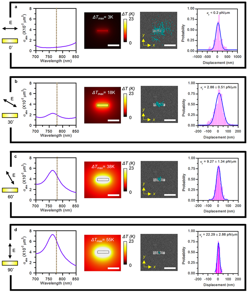
Tunable opto-thermoelectric trapping of a 200 nm PS sphere on an AuNR antenna. Simulated optical absorption cross-sections (first column), simulated in-plane temperature profiles at the AuNR–substrate interface (second column), measured PS sphere position distributions projected on the SEM of the AuNR (third column), and measured histograms of the PS sphere displacements along the y axis of the AuNR (fourth column) for (a) 0°, (b) 30°, (c) 60°, and (d) 90° polarization angles of the laser beam relative to the x axis of the AuNR (see Figure 1d). The leftmost schematics illustrate the relative orientation of the laser beam polarization and the AuNR in planar views (i.e., viewed along the z direction in Figure 1d). A 780 nm laser beam with a power of 1.2 mW/μm2 and a beam size of 2 μm was focused on the AuNR. The scale bars are 500 nm.
We further simulated the polarization-dependent temperature distributions of an AuNR on the glass substrate irradiated by a 780 nm laser beam with a power of 1.2 mW/μm2 (second column in Figure 2a–d). The wave vector of incident light is normal to the substrate. The maximum temperature increases from 3 to 55 K when the polarization angle of incident light is changed from 0° (along the x axis) to 90° (along the y axis). Experimentally, we observed that the polarization-controlled temperature field can tune the opto-thermoelectric trapping stiffness. Specifically, we recorded the trajectories of a 200 nm PS sphere trapped at an AuNR at the different incident light polarizations and calculated the corresponding trapping stiffness, as shown in third and fourth columns of Figure 2a–d. At the polarization of 0°, the temperature gradient was too low to achieve stable trapping of the PS sphere, which exhibited the broad Brownian fluctuation. The trapping stiffness was estimated to be below 0.2 pN/μm. An increased polarization angle improves the temperature gradient and, thus, the trapping stiffness. Briefly, at 30°, the PS sphere was largely trapped at the center of the AuNR, with the measured trapping stiffness of 2.9 pN/μm. The maximum trapping stiffness of 22.3 pN/μm was obtained at 90° (see Supplementary Video 1 for trapping dynamics comparison).
Directed Nanoparticle Transport via the Polarization Control of Heating Light.
Zheng et al. first proposed dynamic transport of nanoparticles using optical near field over a nanostructure surface. It requires little cross-talk and overlap trapping potential walls between the adjacent nanoapertures for successful transport.32 However, the working distance is limited by the skin depths of light (~50 nm). It is worth noting that the decay length of the temperature gradient can be an order higher than that of surface plasmons, which significantly increases the working distance of the opto-thermoelectric trapping for the long-range transport of nano-objects.32,40 Here, we exploit the polarization-dependent trapping behaviors, in combination with rationally designed arrays of thermally coupled nanoantennas, to achieve directed transport of nanoparticles within the diffraction limit by simply controlling the light polarization. To demonstrate the linear transport of the trapped nanoparticle, we fabricated two mutually perpendicular AuNRs of identical dimensions with a center-to-center distance of 1.3 μm (see the scanning electron micrograph in the inset of Figure 3c). A 780 nm laser beam with power density of 1.2 mW/μm2 was used for optical heating, which could excite the transverse surface plasmon mode of the AuNRs. We inserted a linear polarizer in the optical path to control the polarization of the laser beam.
Figure 3.

Directed nanoparticle transport via control of light polarization. A series of time-evolved dark-field optical images show the polarization-controlled (a) linear transport and (b) circular transport of single nanoparticles of 300 nm nanoparticles based on rationally designed AuNR arrays with thermal coupling. T indicates the time. The gray rectangular boxes outline the AuNRs. The red dash circles outline the spots of heating laser beam on the substrates. The laser beam is normal to the substrates with its polarization directions indicated by arrows denoted with E. The brightest spots reveal the nanoparticle positions. Centroid tracking of (c) linear transport and (d) circular transport based on panels a and b. The insets of panels c and d show the SEM of the AuNR pair and AuNR triangle, respectively. Scale bars in panels a and b are 500 nm.
At a polarization of 0°, as indicated in the optical image at T = 0.0 s of Figure 3a and the schematic of Figure 3c, the optically induced temperature of the top AuNR was 10 times higher than that of the bottom AuNR (see Figure S8), leading to the opto-thermoelectric trapping of the nanoparticle on the top AuNR. A rotation of the linear polarizer to 90° flipped the temperature distribution (see Figure S8), which released the nanoparticle from the top AuNR and got it trapped at the bottom AuNR, as shown in the optical image at T = 5.0 s of Figure 3a and the schematic of Figure 3c. At a polarization of 45°, as indicated in the optical image at T = 4.2 s of Figure 3a, the equivalent temperature of the top and bottom AuNRs led to the shuttling of the nanoparticle between the two AuNRs. By continuously rotating the polarization of the laser beam, we can deterministically transport the nanoparticle between the AuNRs (Figure 3a,c; also see Supplementary Video 2).
As another demonstration, we designed a triangle-shape pattern using three AuNRs (see the SEM results in the inset of Figure 3d) to achieve circular transport of nanoparticles. As shown in Figure 3b,d, we have achieved clockwise circular transport of a single 300 nm PS particle by rotating the polarization of the heating laser in a counterclockwise manner (see Supplementary Video 2), and vice versa (see Figure S9).
Opto-Thermoelectric Trapping with Femtosecond Laser Heating.
The steady-state temperature of an optothermal nanoheater depends on its optical absorption, photon–phonon energy conversion, and heat transfer between the nanoheater and the surrounding matrix.41 It is known that a femtosecond (fs) pulse can drastically modify the heat transfer and temperature profile between the nanoheater and the surrounding medium and significantly improve the optical heating effect.42–43 It implies the potentially great difference in opto-thermoelectric trapping behavior between CW and femtosecond. First, we simulated the temperature profiles of a single AuNR irradiated with CW and femtosecond laser beams (Figure 4a,b and Supplementary Note 3 provides details on our temperature simulations). The femtosecond laser heating reduces the heat transfer from the AuNR to surrounding water and thus enhances the thermal confinement at the AuNR. We further compared the opto-thermoelectric trapping of a single PS particle on a single AuNR by femtosecond laser heating with that by CW laser heating. As shown in Figures 4c and d, the femtosecond laser heating led to the narrower spatial distribution of the trapped particle with a 5-fold enhancement of the trapping stiffness without sacrificing the initial trapping range. Although time-dependent temperature profile under a femtosecond laser illumination manifests as multiple pulses, the mean temperature profile is similar as that under CW laser illumination, leading to a similar initial trapping range.43 However, once the particle gets trapped, similar to plasmonic and optical tweezers with which the dynamics of Rayleigh particles are affected by the strong transient optical force, the temporal impulsive peak power of femtosecond laser improves spatial separation of the ions, increases the thermoelectric field and the temperature gradient with high transient thermophoretic force, thus improving the trapping stability.44,45 To preclude the convection flow for the particle movement, we simulated the thermal induced the convection under femtosecond laser excitation (see Figure S10). It shows the flow velocity in the y axis is below 10−10 m/S, which is not large enough to drive the particle movement.
Figure 4.

Opto-thermoelectric trapping with femtosecond laser heating. Temperature profiles at the AuNR–substrate interface irradiated with (a) CW and (b) femtosecond laser beams of 0.3 mW/μm2, respectively. Scale bars in panels a and b are 200 nm. Measured position distributions of a single 500 nm PS particle along with histograms of the particle displacement along the y axis for (c) CW and (d) femtosecond laser heating. Scale bars in panels a and b are 200 nm. (e) Schematic of the emission lifetime measurement for the AuNR antennas and quantum dots (QDs). AuNRs have blue-green second harmonic emission (peak wavelength: 490 nm), while QDs have red emission (peak wavelength: 615 nm). The inset is the fluorescence image of a CdSe/CdS trapped QD. Scale bar in panel e is 200 nm. (f) Tracking of fluorescence intensity of the trapped QD and estimated number of trapped QDs as a function of time. The single QD region is highlighted as a gray region. (g) Time-evolved fluorescence lifetime of single QDs that underwent free motion, trapping at the nanoantenna, and release to free motion from the laser-on to the laser-off time period. (h) Fluorescence lifetimes of free and trapped QDs under the variable CTAC concentrations.
It is worthy to mention that, under the femotosecond laser illumination, particles and CTAC micelles can no longer move for an appreciable distance by the diffusion. According to the Stokes–Einstein equation, we estimated that the diffusion coefficients (D) for a 500 nm PS particle is ~0.5 μm2/s, while the diffusion coefficients for CTAC micelle are above 30 μm2/s.46,47 The motion of PS particle responds more slowly to the femtosecond pulse than that of CTAC micelles.48 Thus, the impulsive peak power of a femtosecond laser can generate a strong transient electric field from CTAC micelle redistribution to improve the trapping stability. In addition, the more-sluggish diffusion of PS particle under laser relaxation also makes sure that the trapped particle will not escape the trapping site prior to the next pulse.
With the improved trapping stability using femtosecond laser heating, we have achieved the opto-thermoelectric trapping and in situ characterization of ultrasmall nanoparticles on single AuNR antennas at low power. These include CdSe/CdS core/shell quantum dots (QDs) with the size of ~30 nm. To detect the trapped QDs at the AuNRs, we used two-photon fluorescence to excite the photon emission of the QDs (with an emission peak wavelength of 615 nm), which was spectrally separated from the second harmonic emission of the AuNRs (with an emission peak wavelength of 490 nm) (Figure 4e) with a dual-channel photodetector setup (see Figure S11). With the heating laser power density of 0.5 mW/μm2 below the melting power of the AuNR, we could visualize the trapped single QDs via a charge-coupled device (CCD) camera (inset of Figure 4e), and the recorded two-photon fluorescence signal from the QDs showed a characteristic blinking dynamic (Figure 4f). The stepwise features show the dynamics from single QDs to multiple QDs trapping. We also observe larger fluorescence fluctuation when we trap multiple QDs, which might be attributed to the relative motion among the QDs leading to variations in the fluorescence counts.49 Indeed, the minimum trapping power can be even lower. However, it is out of the single QD lifetime detection limit when we reduce the laser power lower than 0.5 mW/μm2.
Controlling the distance between plasmonic antennas and QDs distance is critical for applications in quantum plasmonics. Besides working as a nanoheater for the opto-thermoelectric trapping, the AuNR can simultaneously act as a plasmonic cavity to tune optical responses of the nearby QDs via the plasmon–exciton coupling. We carried out in situ two-photon fluorescence lifetime measurement for the QDs to gain an insight into the AuNR-QD interactions (Figure S11). Figure 4g shows the time-evolved QD fluorescence lifetime when a QD sequentially underwent nontrapping, trapping, and release events. Further, we measured the fluorescence lifetime of the trapped QDs at the variable CTAC concentrations, which can tune the depletion attraction between the QDs and nanoantenna.31 Figure 4h shows that the mean lifetime of the trapped QDs decreased from 9.5 to 7 ns when the CTAC concentration was increased from 5 mM to 20 mM (also see Figure S12). In contrast, the fluorescence lifetime of free QDs maintained a constant value of 10.5 ns at variable CTAC concentrations (Figure 4h; also see Figure S13), ruling out the influence of CTAC on the QD fluorescence lifetime. We attribute the lifetime reduction to the reduced AuNR-QD distance. As the CTAC concentration increases, the depletion of CTAC micelles between AuNR-QD can weaken their electrostatic repulsion and thus reduce AuNR-QD gap.
CONCLUSIONS
We exploit light-generated temperature gradient to achieve the opto-thermoelectric trapping of varied nano-objects at single metal nanoantenna or nanoradiators. The opto-thermoelectric trapping is distinguished from the plasmon-enhanced optical trapping. With an enhanced working distance of the temperature gradient field over surface plasmons and the rationally designed nanoantenna arrays, we have further achieved directed transport of the nanoparticles by simply controlling light polarization. An improved control of heat transfer using femtosecond laser heating further enhances the trapping stability, which enables the precise manipulation of single CdSe/CdS core–shell QDs at the nanoantenna with tunable plasmon–exciton interaction. Indeed, a full understanding of the opto-thermoelectric mechanism is still challenging because of the entanglement of thermo-osmosis, thermophoresis, convection, and thermal-induced depletion attraction in our system. We expect that the ongoing theoretical and experimental studies on the interfacial thermal nonequilibrium effects could provide an insight into the mechanism.50–53 Nevertheless, our work presents an improved understanding and control of the opto-thermoelectric effects toward versatile and precise manipulation of nanoparticles. With multiple degrees of freedom in terms of low operation power, dynamic transport, and tunable light–matter interaction, the opto-thermoelectric manipulation using designed nanoheaters will find applications in nanofabrication, sensing, and nanobiophotonics.
METHODS
Sample Preparation.
We fabricated nanoantennas by electron beam lithography (EBL). The pattern was defined by spin-coating PMMA and E-spacer on a 2 in. glass substrate followed by a a standard EBL process. After the electron-beam writing, the sample was developed in 3:1 IPA/MIBK for 60 s. Cr (2 nm) and Au (18 nm) were deposited on the substrate by thermal deposition, followed by the lift-off process with acetone.
AuNS (100 nm, Sigma-Aldrich) and AgNS (100 nm, nanoComposix) were purchased and redispersed in solutions with targeted CTAC concentrations. Polystyrene beads (200 and 300 nm, Bangs Laboratories Inc.) were purchased and redispersed in solutions with targeted CTAC concentrations. CdSe/CdS core–shell water-soluble QDs with red (615 nm) emission were synthesized, purified and stored in chloroform. An amphiphilic polymer (PMAO–PEG) (molar ratio of PMAO to PEG was 1:10) was produced from the overnight reaction of poly(maleic anhydride-alt- 1-octadecene) (PMAO) and amino poly(ethylene glycol) methyl ether (PEG) in chloroform. The QDs and PMAO–PEG (molar ratio of QD to PMAO–PEG was 1:10) were combined and stirred in chloroform for 1 h at room temperature. Water and chloroform (1:1 v/v) were added, and chloroform was slowly removed via rotary evaporation at room temperature. This led to a clear and colored solution of the water-soluble QDs. An ultracentrifuge (Beckman Coulter Optima L-80XP) was used to further concentrate and remove excessive amphiphilic polymer. The original QD solution concentration determined using the extinction coefficients was 0.2 μM. The QD stock solution was diluted 1:40 v/v in deionized water. To perform the trapping experiments, we added QDs to solutions with desired CTAC concentrations.
Continuous-Wave-Laser Trapping Setup.
The CW trapping was achieved using a 780 nm diode-pumped solid-state laser. The laser beam was expanded with a 10× beam expander. A 100× oil objective (Nikon, NA of 0.5–1.3) was used to focus the laser beam in an inverted optical microscope (Nikon Ti-E). An air condenser (NAof 0.95–0.8) was used for optical imaging of AgNS and AuNS. A fluorescence lamp was used to excite the fluorescent polystyrene particles with an emission wavelength of ~615 nm. To record optical images and track particle motion, a color CCD camera (Nikon) and a fast-monochromic CCD camera (Andor) were used, respectively.
Femtosecond-Laser Trapping Setup.
The femtosecond laser trapping was achieved using a titanium: sapphire laser tuned to 780 nm (~200 fs) (Mira 900, Coherent). A silicone oil-immersion lens with an NA of 1.3 (UPLSAPO60X, Olympus) was used. To measure the lifetime of the QDs, time-correlated single photon counting (TCSPC) was employed with galvo scanning mirrors (6215H, Cambridge Tech.) and a GaAsP photomultiplier tube (PMT) (H7422PA-40, Hamamatsu) in a non-descanned detection scheme. The output current of the PMT was amplified using a preamplifier with 2 GHz cutoff (HFAC-26, Becker and Hickl GmbH). The amplified pulses from the PMTs were sent to the TCSPC module (SPC-150, Becker and Hickl GmbH). Fluorescence lifetime was recorded with a 20 ps time resolution, a pixel integration time of 5 ms, and variable incident power. The least-squares method using a model of a double exponential decay convolved with a Gaussian impulse function was utilized to perform lifetime fitting.
Numerical Simulation.
We simulated the electromagnetic field distribution and the absorption cross-section of plasmonic nanoantenna using finite-difference time-domain (FDTD) method (lumerical FDTD). We defined the mesh size as 2 nm for plasmonic nanoantennas. A refractive index of 1.33 was used for water environment. The heat density was calculated by , where σabs was the absorption cross-section obtained using FDTD simulations, I was the illumination intensity, and VNR was the volume of the AuNR. By assuming the high thermal conductivity of the gold, we simulated the temperature field profile using three-dimensional finite element method. Heat-transfer module and laminar flow coupled with nonisothermal flow were used to simulate the steady-state temperature distribution and fluidic dynamic. The outer boundaries were set at room temperature.
Supplementary Material
ACKNOWLEDGMENTS
Y.Z., L.L., Y.L., B.B.R., X.P.,P.K., and K.Y. acknowledge the financial supports of the Army Research Office (W911NF-17-1-0561), the National Aeronautics and Space Administration Early Career Faculty Award (80NSSC17K0520) and the National Institute of General Medical Sciences of the National Institutes of Health (DP2GM128446). We thank the Texas Advanced Computing Centre at The University of Texas at Austin (http://www.tacc.utexas.edu) for providing HPC resources that have contributed to the research results reported within this paper. We also thank Phasics (http://www.phasicscorp.com) for the temperature measurement of the nanorod using SID4-bio imaging camera and TIQSI technique.
Footnotes
Supporting Information
The Supporting Information is available free of charge on the ACS Publications website at DOI: 10.1021/acsnano.8b05824.
A video showing opto-thermoelectric trapping of 100 nm Au nanosphere (AuNS), 100 nm Ag nanosphere (AgNS), 200 nm polystyrene (PS) sphere, and CdSe/CdS quantum dots on a single AuNR as well as trapping dynamics of 200 nm PS sphere arising from the switching of light polarization between 0 and 90 degrees (MP4)
A video showing directed transport of particles: linear transport of a single 300 nm PS sphere and circular transport of a single 300 nm PS sphere (MP4)
Figures, details and a table regarding the ζ potentials of nanoparticles, temperature measurements, optical scattering specrta, analysis of optical coupling, optical force simulation and optical responses, temperature profiles, thermal convection flow, femtosecond laser trapping and in situ spectroscopy of quantum dots, trapping positions of metal particles, optothermal electrical fields and force, temperature simulations, and equation parameters (PDF)
The authors declare no competing financial interest.
REFERENCES
- (1).Grigorenko A; Roberts N; Dickinson M; Zhang Y Nanometric Optical Tweezers Based on Nanostructured Substrates. Nat. Photonics 2008, 2, 365. [Google Scholar]
- (2).Jamshidi A; Pauzauskie PJ; Schuck PJ; Ohta AT; Chiou P-Y; Chou J; Yang P; Wu MC Dynamic Manipulation and Separation of Individual Semiconducting and Metallic Nanowires. Nat. Photonics 2008, 2, 86. [DOI] [PMC free article] [PubMed] [Google Scholar]
- (3).Moffitt JR; Chemla YR; Smith SB; Bustamante C Recent Advances in Optical Tweezers. Annu. Rev. Biochem 2008, 77, 205–228. [DOI] [PubMed] [Google Scholar]
- (4).Yang AH; Moore SD; Schmidt BS; Klug M; Lipson M; Erickson D Optical Manipulation of Nanoparticles and Biomolecules in Sub-Wavelength Slot Waveguides. Nature 2009, 457, 71. [DOI] [PubMed] [Google Scholar]
- (5).Krishnan M; Mojarad N; Kukura P; Sandoghdar V Geometry-Induced Electrostatic Trapping of Nanometric Objects in a Fluid. Nature 2010, 467, 692. [DOI] [PubMed] [Google Scholar]
- (6).Neuman KC; Nagy A Single-Molecule Force Spectroscopy: Optical Tweezers, Magnetic Tweezers and Atomic Force Microscopy. Nat. Methods 2008, 5, 491. [DOI] [PMC free article] [PubMed] [Google Scholar]
- (7).Zhao C Practical Guide to the Realization of a Convertible Optical Trapping System. Opt. Express 2017, 25, 2496–2510. [DOI] [PubMed] [Google Scholar]
- (8).Zhang T; Mahdy MRC; Liu Y; Teng JH; Lim CT; Wang Z; Qiu C-W All-Optical Chirality-Sensitive Sorting via Reversible Lateral Forces in Interference Fields. ACS Nano 2017, 11, 4292–4300. [DOI] [PubMed] [Google Scholar]
- (9).Fedoruk M; Meixner M; Carretero-Palacios S; Lohmuller T; Feldmann J Nanolithography by Plasmonic Heating and Optical Manipulation of Gold Nanoparticles. ACS Nano 2013, 7, 7648–53. [DOI] [PubMed] [Google Scholar]
- (10).Ashkin A; Dziedzic JM; Yamane T Optical Trapping and Manipulation of Single Cells Using Infrared Laser Beams. Nature 1987, 330, 769. [DOI] [PubMed] [Google Scholar]
- (11).Wang MD; Yin H; Landick R; Gelles J; Block SM Stretching DNA with Optical Tweezers. Biophys. J 1997, 72, 1335–1346. [DOI] [PMC free article] [PubMed] [Google Scholar]
- (12).Svedberg F; Li ZP; Xu HX; Kall M Creating Hot Nanoparticle Pairs for Surface-Enhanced Raman Spectroscopy through Optical Manipulation. Nano Lett. 2006, 6, 2639–2641. [DOI] [PubMed] [Google Scholar]
- (13).Alam MS; Karim F; Zhao C Single-Molecule Detection at High Concentrations with Optical Aperture Nanoantennas. Nanoscale 2016, 8, 9480–9487. [DOI] [PubMed] [Google Scholar]
- (14).Grier DG A Revolution in Optical Manipulation. Nature 2003, 424, 810–6. [DOI] [PubMed] [Google Scholar]
- (15).Righini M; Zelenina AS; Girard C; Quidant R Parallel and Selective Trapping in a Patterned Plasmonic Landscape. Nat. Phys 2007, 3, 477. [Google Scholar]
- (16).Pang Y; Gordon R Optical Trapping of a Single Protein. Nano Lett. 2012, 12, 402–406. [DOI] [PubMed] [Google Scholar]
- (17).Roxworthy BJ; Ko KD; Kumar A; Fung KH; Chow EK; Liu GL; Fang NX; Toussaint KC Jr Application of Plasmonic Bowtie Nanoantenna Arrays for Optical Trapping, Stacking, and Sorting. Nano Lett. 2012, 12, 796–801. [DOI] [PubMed] [Google Scholar]
- (18).Righini M; Ghenuche P; Cherukulappurath S; Myroshnychenko V; García de Abajo F; Quidant R Nano-Optical Trapping of Rayleigh Particles and Escherichia Coli Bacteria with Resonant Optical Antennas. Nano Lett. 2009, 9, 3387–3391. [DOI] [PubMed] [Google Scholar]
- (19).Zhang W; Huang L; Santschi C; Martin OJ Trapping and Sensing 10 nm Metal Nanoparticles Using Plasmonic Dipole Antennas. Nano Lett. 2010, 10, 1006–1011. [DOI] [PubMed] [Google Scholar]
- (20).Gahagan K; Swartzlander G Optical Vortex Trapping of Particles. Opt. Lett 1996, 21, 827–829. [DOI] [PubMed] [Google Scholar]
- (21).Wang K; Schonbrun E; Steinvurzel P; Crozier KB Trapping and Rotating Nanoparticles Using a Plasmonic Nano-Tweezer with an Integrated Heat Sink. Nat. Commun 2011, 2, 469. [DOI] [PubMed] [Google Scholar]
- (22).Gargiulo J; Brick T; Violi IL; Herrera FC; Shibanuma T; Albella P; Requejo FG; Cortes E; Maier SA; Stefani FD Understanding and Reducing Photothermal Forces for the Fabrication of Au Nanoparticle Dimers by Optical Printing. Nano Lett. 2017, 17, 5747–5755. [DOI] [PubMed] [Google Scholar]
- (23).Braun D; Libchaber A Trapping of DNA by Thermophoretic Depletion and Convection. Phys. Rev. Lett 2002, 89, 188103. [DOI] [PubMed] [Google Scholar]
- (24).Jiang HR; Wada H; Yoshinaga N; Sano M Manipulation of Colloids by a Nonequilibrium Depletion Force in a Temperature Gradient. Phys. Rev. Lett 2009, 102, 208301. [DOI] [PubMed] [Google Scholar]
- (25).Braun M; Cichos F Optically Controlled Thermophoretic Trapping of Single Nano-Objects. ACS Nano 2013, 7, 11200–11208. [DOI] [PubMed] [Google Scholar]
- (26).Braun M; Bregulla AP; Gunther K; Mertig M; Cichos F Single Molecules Trapped by Dynamic Inhomogeneous Temperature Fields. Nano Lett. 2015, 15, 5499–5505. [DOI] [PubMed] [Google Scholar]
- (27).Ndukaife JC; Mishra A; Guler U; Nnanna AG; Wereley ST; Boltasseva A Photothermal Heating Enabled by Plasmonic Nanostructures for Electrokinetic Manipulation and Sorting of Particles. ACS Nano 2014, 8, 9035–43. [DOI] [PubMed] [Google Scholar]
- (28).Ndukaife JC; Kildishev AV; Nnanna AGA; Shalaev VM; Wereley ST; Boltasseva A Long-Range and Rapid Transport of Individual Nano-Objects by a Hybrid Electrothermoplasmonic Nanotweezer. Nat. Nanotechnol 2016, 11, 53. [DOI] [PubMed] [Google Scholar]
- (29).Lin LH; Peng XL; Mao ZM; Wei XL; Xie C; Zheng YB Interfacial-Entropy-Driven Thermophoretic Tweezers. Lab Chip 2017, 17, 3061–3070. [DOI] [PubMed] [Google Scholar]
- (30).Lin LH; Peng XL; Wei XL; Mao ZM; Xie C; Zheng YB Thermophoretic Tweezers for Low-Power and Versatile Manipulation of Biological Cells. ACS Nano 2017, 11, 3147–3154. [DOI] [PubMed] [Google Scholar]
- (31).Lin L; Wang MS; Peng XL; Lissek EN; Mao ZM; Scarabelli L; Adkins E; Coskun S; Unalan HE; Korgel BA; Liz-Marzan LM; Florin EL; Zheng YB Opto-Thermoelectric Nanotweezers. Nat. Photonics 2018, 12, 195–201. [DOI] [PMC free article] [PubMed] [Google Scholar]
- (32).Zheng YX; Ryan J; Hansen P; Cheng YT; Lu TJ; Hesselink L Nano-Optical Conveyor Belt, Part II: Demonstration of Handoff between Near-Field Optical Traps. Nano Lett. 2014, 14, 2971–2976. [DOI] [PubMed] [Google Scholar]
- (33).Tsai WY; Huang JS; Huang CB Selective Trapping or Rotation of Isotropic Dielectric Microparticles by Optical Near Field in a Plasmonic Archimedes Spiral. Nano Lett. 2014, 14, 547–52. [DOI] [PubMed] [Google Scholar]
- (34).Huft PR; Kolbow JD; Thweatt JT; Lindquist NC Holographic Plasmonic Nanotweezers for Dynamic Trapping and Manipulation. Nano Lett. 2017, 17, 7920–7925. [DOI] [PubMed] [Google Scholar]
- (35).Baffou G; Quidant R; de Abajo FJG Nanoscale Control of Optical Heating in Complex Plasmonic Systems. ACS Nano 2010, 4, 709–716. [DOI] [PubMed] [Google Scholar]
- (36).Ma HY; Bendix PM; Oddershede LB Large-Scale Orientation Dependent Heating from a Single Irradiated Gold Nanorod. Nano Lett. 2012, 12, 3954–3960. [DOI] [PubMed] [Google Scholar]
- (37).Baffou G; Bon P; Savatier J; Polleux J; Zhu M; Merlin M; Rigneault H; Monneret S Thermal Imaging of Nanostructures by Quantitative Optical Phase Analysis. ACS Nano 2012, 6, 2452–2458. [DOI] [PubMed] [Google Scholar]
- (38).Baffou G; Quidant R Thermo-Plasmonics: Using Metallic Nanostructures as Nano-Sources of Heat. Laser Photonics Rev. 2013, 7, 171–187. [Google Scholar]
- (39).Min CJ; Shen Z; Shen JF; Zhang YQ; Fang H; Yuan GH; Du LP; Zhu SW; Lei T; Yuan XC Focused Plasmonic Trapping of Metallic Particles. Nat. Commun 2013, 4, 2891. [DOI] [PMC free article] [PubMed] [Google Scholar]
- (40).Hansen P; Zheng YX; Ryan J; Hesselink L Nano-Optical Conveyor Belt, Part I: Theory. Nano Lett. 2014, 14, 2965–2970. [DOI] [PubMed] [Google Scholar]
- (41).Richardson HH; Carlson MT; Tandler PJ; Hernandez P; Govorov AO Experimental and Theoretical Studies of Light-to-Heat Conversion and Collective Heating Effects in Metal Nanoparticle Solutions. Nano Lett. 2009, 9, 1139–1146. [DOI] [PMC free article] [PubMed] [Google Scholar]
- (42).Baffou G; Rigneault H Femtosecond-Pulsed Optical Heating of Gold Nanoparticles. Phys. Rev. B: Condens. Matter Mater. Phys 2011, 84, 035415. [Google Scholar]
- (43).Baffou G; Berto P; Bermúdez Ureña E; Quidant R; Monneret S; Polleux J; Rigneault H Photoinduced Heating of Nanoparticle Arrays. ACS Nano 2013, 7, 6478–6488. [DOI] [PubMed] [Google Scholar]
- (44).Roxworthy BJ; Toussaint KC, Jr Femtosecond-Pulsed Plasmonic Nanotweezers. Sci. Rep 2012, 2, 660. [DOI] [PMC free article] [PubMed] [Google Scholar]
- (45).Muramatsu M; Shen TF; Chiang WY; Usman A; Masuhara H Picosecond Motional Relaxation of Nanoparticles in Femtosecond Laser Trapping. J. Phys. Chem. C 2016, 120, 5251–5256. [Google Scholar]
- (46).Davis JM Determination of Micellar Self-Diffusion Coefficients by Micellar Electrokinetic Chromatography. Analyst 1998, 123, 337–341. [DOI] [PubMed] [Google Scholar]
- (47).Mandal AB; Nair BU Cyclic Voltammetric Technique for the Determination of the Critical Micelle Concentration of Surfactants, Self-Diffusion Coefficient of Micelles, and Partition Coefficient of an Electrochemical Probe. J. Phys. Chem 1991, 95, 9008–9013. [Google Scholar]
- (48).Liu TH; Chiang WY; Usman A; Masuhara H Optical Trapping Dynamics of a Single Polystyrene Sphere: Continuous Wave versus Femtosecond Lasers. J. Phys. Chem. C 2016, 120, 2392–2399. [Google Scholar]
- (49).Roy D; Goswami D; De AK Exploring the Physics of Efficient Optical Trapping of Dielectric Nanoparticles with Ultrafast Pulsed Excitation. Appl. Opt 2015, 54, 7002–7006. [DOI] [PubMed] [Google Scholar]
- (50).Bregulla AP; Wurger A; Gunther K; Mertig M; Cichos F Thermo-Osmotic Flow in Thin Films. Phys. Rev. Lett 2016, 116, 188303. [DOI] [PubMed] [Google Scholar]
- (51).Fu L; Merabia S; Joly L What Controls Thermo-Osmosis? Molecular Simulations Show the Critical Role of Interfacial Hydrodynamics. Phys. Rev. Lett 2017, 119, 214501. [DOI] [PubMed] [Google Scholar]
- (52).Wurger A Hydrodynamic Boundary Effects on Thermophoresis of Confined Colloids. Phys. Rev. Lett 2016, 116, 138302. [DOI] [PubMed] [Google Scholar]
- (53).Ganti R; Liu Y; Frenkel D Molecular Simulation of Thermo-Osmotic Slip. Phys. Rev. Lett 2017, 119, 038002. [DOI] [PubMed] [Google Scholar]
Associated Data
This section collects any data citations, data availability statements, or supplementary materials included in this article.