Abstract
Cancer metastasis is known to cause 90% of cancer lethality. Metastasis is a multistage process which initiates with the penetration/invasion of tumor cells into neighboring tissue. Thus, invasion is a crucial step in metastasis, making the invasion process research and development of anti-metastatic drugs, highly significant. To address this demand, there is a need to develop 3D in vitro models which imitate the architecture of solid tumors and their microenvironment most closely to in vivo state on one hand, but at the same time be reproducible, robust and suitable for high yield and high content measurements. Currently, most invasion assays lean on sophisticated microfluidic technologies which are adequate for research but not for high volume drug screening. Other assays using plate-based devices with isolated individual spheroids in each well are material consuming and have low sample size per condition. The goal of the current protocol is to provide a simple and reproducible biomimetic 3D cell-based system for the analysis of invasion capacity in large populations of tumor spheroids. We developed a 3D model for invasion assay based on HMCA imaging plate for the research of tumor invasion and anti-metastatic drug discovery. This device enables the production of numerous uniform spheroids per well (high sample size per condition) surrounded by ECM components, while continuously and simultaneously observing and measuring the spheroids at single-element resolution for medium throughput screening of anti-metastatic drugs. This platform is presented here by the production of HeLa and MCF7 spheroids for exemplifying single cell and collective invasion. We compare the influence of the ECM component hyaluronic acid (HA) on the invasive capacity of collagen surrounding HeLa spheroids. Finally, we introduce Fisetin (invasion inhibitor) to HeLa spheroids and nitric oxide (NO) (invasion activator) to MCF7 spheroids. The results are analyzed by in-house software which enables semi-automatic, simple and fast analysis which facilitates multi-parameter examination.
Keywords: Cancer Research, Issue 140, 3D multicellular objects, spheroid, hydrogel, micro-chamber, invasion assay, ECM, image analysis, collective invasion, 3D culture model
Introduction
Cancer death is attributed mainly to the dissemination of metastatic cells to distant locations. Many efforts in cancer treatment focus on targeting or preventing the formation of metastatic colonies and progression of systemic metastatic disease1. Cancer cell migration is a crucial step in the tumor metastasis process, thus, the research of the cancer invasion cascade is very important and a prerequisite to finding anti-metastatic therapeutics.
The use of animal models as tools for studying metastatic disease has been found to be very expensive and not always representative of the tumor in humans. Moreover, the extracellular microenvironment topology, mechanics and composition strongly affect cancer cell behavior2. Since in vivo models inherently lack the ability to separate and control such specific parameters which contribute to cancer invasion and metastasis, there is a need for controllable biomimetic in vitro models.
In order to metastasize to distant organs, cancer cells must exhibit migratory and invasive phenotypic traits which can be targeted for therapy. However, since most in vitro cancer models do not mimic the actual features of solid tumors3, it is very challenging to detect physiologically relevant phenotypes. In addition, the phenotypic heterogeneity that exists within the tumor, dictates the need for analyzing tumor migration at single-element resolution in order to discover phenotype-directed therapies, for instance, by targeting the metastasis-initiating cell population within heterogeneous tumors4.
The study of cell motility and collective migration is primarily conducted in monolayer cultures of epithelial cells on homogeneous planar surfaces. These conventional cellular models for cancer cell migration are based on the population analysis of individual cells invading through the membranes and ECM components5, but in such systems, the intrinsic differences between individual cells cannot be studied. Generating 3D spheroids either via scaffolds or in scaffold-free micro-structures is considered as a superior means to study the tumor cell growth and cancer invasion6,7,8. However, most 3D systems are not suitable to high throughput formats, and inter-spheroid interaction cannot usually be achieved since isolated individual spheroids are generated in each micro-well9. Recent studies involving the cancer migration are based on microfluidic devices3,10,11,12, however, these sophisticated microfluidic tools are difficult to produce and cannot be used for high throughput screening (HTS) of anti-invasive drugs.
Two main phenotypes, collective and individual cell migration, which play a role in tumor cells overcoming the ECM barrier and invading neighboring tissue, have been demonstrated13,14, each displaying distinct morphological characteristics, biochemical, molecular and genetic mechanisms. In addition, two forms of migrating tumor cells, fibroblast-like and amoeboid, are observed in each phenotype. Since both, invasion phenotypes and migration modes, are mainly defined by morphological properties, there is a need for cellular models that enable imaging-based detection and examination of all forms of tumor invasion and migrating cells.
The overall goal of the current method is to provide a simple and reproducible biomimetic 3D in vitro cell-based system for the analysis of invasion capacity in large populations of tumor spheroids. Here, we introduce the HMCA-based 6-well imaging plate for the research of tumor invasion and anti-metastatic therapy. The technology enables the formation of large numbers of uniform 3D tumor spheroids (450 per well) in a hydrogel micro-chambers (MC) structure. Various ECM components are added to the spheroid array to enable the invasion of the cells into the surrounding environment. Invasion process is continuously monitored by short- and long-term observation of the same individual spheroids/invading cells and facilitates morphological characterization, fluorescent staining and retrieval of specific spheroids at any point. Since numerous spheroids share space and medium, interaction via soluble molecules between individual spheroids and their impact on one another is possible. Semi-automatic image analysis is performed by using in-house MATLAB code which enables faster and more efficient collection of large amount of data. The platform facilitates accurate, simultaneous measurement of numerous spheroids/invading cells in a time-efficient manner, allowing medium throughput screening of anti-invasion drugs.
Protocol
1. HMCA Plate Embossing
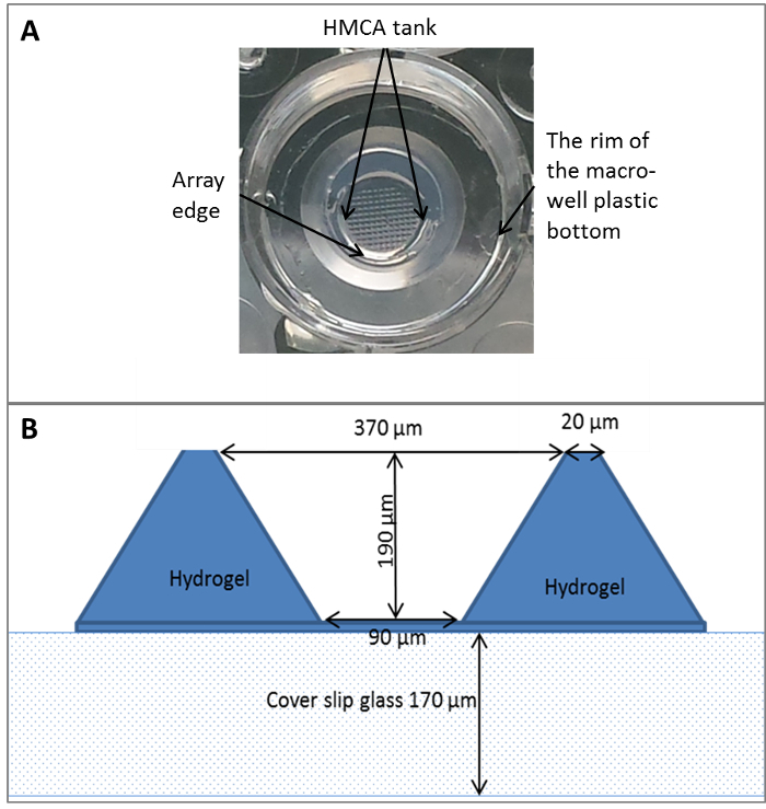
NOTE: The complete process for the design and fabrication of polydimethylsiloxane (PDMS) stamp and HMCA imaging plate used in this protocol is described in detail in our previous articles15,16. The PDMS stamp (negative shape) is used to emboss the HMCA (positive shape) which consists of approximately 450 MCs per well (Figure 1A). As demonstrated in Figure 1B, each of the MCs has a shape of a truncated upside-down square-shaped pyramid (height: 190 µm, small base area: 90 µm x 90 µm, and large base area: 370 µm x 370 µm). The HMCA plate is used for the preparation and culturing of 3D tumor spheroids and thereafter, for invasion assay. Alternatively, a commercial stamp could be used for HMCA production.
Prepare a solution of 6% low melting agarose (LMA). Insert the LMA powder and sterile phosphate buffered saline (PBS) (0.6 g of LMA per 10 mL of PBS) into a glass bottle with a magnetic stirrer. Place the bottle on a heating plate and stir the solution while heating to 80 °C for a few hours until a uniform solution is achieved. Keep the solution at 70 °C until use.
Pre-heat the PDMS stamp to 70 °C in the oven. Keep it warm until use. Alternatively, use a commercial stamp and follow the instruction.
Place the commercial 6-well glass-bottom plates on a dry bath pre-heated to 75 °C. Wait a few minutes until the plate is totally warm.
Pour a drop (400 µL) of pre-heated LMA onto the glass bottom of each one of the wells in the plate. Gently place the pre-heated PDMS stamp over the agarose drop. Incubate at room temperature (RT) for 5–10 min for pre-gelling and pre-cooling. Incubate at 4 °C for 20 min to achieve full agarose gelation. Then, gently peel off the PDMS, leaving the agarose gel patterned with MCs. NOTE: This step is done simultaneously in all the wells.
Place the embossed plate in a light curing system equipped with ultraviolet (UV) lamp, and incubate for 3 min. NOTE: Now the HMCA plate is UV sterilized.
Fill the macro-wells with sterile PBS to ensure that they are kept humid, then cover the plate, wrap it with parafilm and store it at 4 °C until use.
Before use, empty PBS residuals from the HMCA plate. Place it in the biological hood.
2. Loading Cells and Spheroid Formation
Collect the cells as follows: remove all medium from a 10 cm culture plate cell monolayer, wash twice with 10 mL of PBS to dispose of serum residuals, add 5 mL of trypsin (pre-warmed to 37 °C) and incubate for 3 min in the incubator at 37 °C. Then, shake the plate gently to ensure monolayer detachment, add 10 mL of complete medium (pre-warmed to 37 °C) and pipette up and down until homogenous cell suspension is achieved. Centrifuge and wash the cell suspension with 15 mL of fresh medium, then, suspend at appropriate concentrations in fresh complete medium.
Gently load the cell suspension (50 µL, 150–360 x 103 cells/mL in medium, ~16–40 cells per MC) on top of the HMCA and allow the cells to settle by gravity for 15 min.
Gently add 6–8 aliquots of 500 µL fresh medium (total 3–4 mL) to the rim of the macro-well plastic bottom outside the ring and hydrogel array.
Incubate HeLa cells for 72 h and MCF7 cells for 48 h at 37 °C and 5% CO2, in a humidified atmosphere for the formation of spheroids.
3. Viability Detection by Propidium Iodide (PI) Staining
Prepare a stock solution of PI (500 µg of PI per 1 mL of PBS). Keep it at 4 °C for about 6 months. Freshly prepare a dilution of 1:2,000 (0.25 µg/mL), by the addition of 6 µL of stock to 12 mL of complete medium without phenol red, for the 6-well HMCA plate (2 mL per well).
Transfer the HMCA plate with 48-72 h spheroids, from the incubator to the biological hood. Remove all medium from the HMCA by leaning the tip end on the edge of the macro-well plastic bottom beside the hydrogel array, leaving the array tank filled with medium.
Gently add 2 mL of PI dilution from Step 3.1 to each well, by leaning the tip end on the edge of the macro-well plastic bottom. Incubate the HMCA plate for 1 h at 37 °C and 5% CO2, in a humidified atmosphere. Continue to Step 7. NOTE: Other dyes could be used here as well, for example, Hoechst for nucleus staining, tetramethylrhodamine methyl ester (TMRM) for mitochondrial membrane potential staining, fluorescein diacetate (FDA) for live cells detection, Annexin V for apoptosis detection and others.
4. Collagen Mixture Preparation
Prepare sterile double distilled water (DDW) by autoclave and a stock of 100 mL of 1 M NaOH filter-sterilized solution. Maintain the materials at RT, and the tips used for collagen mixture preparation frozen at -20 °C, until use.
10–20 min before use, place all intergrades including: sterile DDW, 1 M NaOH sterile solution, sterile 10x PBS, type I collagen from rat tail (stored at 4 °C for 3– months) and a sterile tube into the ice bucket until totally cooled. Place the ice bucket inside the biological hood.
Prepare 1,800 µL of collagen mixture at a final concentration of 3 mg/mL, for 6-well HMCA invasion assay plate (300 µL per well) as follows. Add the intergrades into the cooled tube in the following order: 515 µL of DDW, 24.8 µL of 1 M NaOH and 180 µL of 10x PBS. Mix well by vortex and place back into the ice. Finally, add 1080 µL of collagen to the mixture, vortex again and put back into ice.
5. HA and Collagen Mixture Preparation
Dissolve 10 mg of HA in 2 mL of sterile DDW. Incubate the mixture at RT for a few minutes and vortex gently until the powder is totally dissolved. Store the stock solution at 4 °C for up to two years.
Right before use, place the HA stock solution in the ice bucket inside the biological hood.
Prepare a 3 mg/mL collagen mixture as described in Step 4. Add 36 µg (7.2 µL) of HA into 1,800 μL of ready to use collagen mixture, for a final concentration of 20 µg/mL. Then, vortex again briefly and put back into ice.
6. ECM Mixture Addition
Transfer the HMCA plate, with 48–72 h spheroids, from the incubator into the biological hood and place it on the ice. Incubate for 10 min until the plate is cooled. Pre-heat a solution of 1% LMA to 37 °C in a water bath.
Remove all medium from around the HMCA, by leaning the tip end on the edge of the macro-well plastic bottom beside the hydrogel array. Then, very carefully, remove all medium from the array tank with a fine tip/gel loading tip, by leaning the tip end on the array edge, gently and slowly sucking all medium out. NOTE: After removing all medium from around the hydrogel array, the array tank is still filled with medium. This medium has to be removed very gently in order to avoid destruction of the hydrogel MC and dislocation of spheroids.
Take 150 µL of the collagen mixture or HA and collagen mixture (ECM mixture) with the pre-frozen fine tip and add into the array tank by attaching the tip to the array edge. Release the mixture slowly to avoid spheroid dislocation. Repeat this step with another aliquot of 150 µL, for a total 300 µL per well. Follow the same procedure for each well until all wells are filled. Then place the plate into the incubator for 1 h for the full gelation of the ECM.
After the full gelation of ECM has been achieved, pipette 400 µL of pre-warmed 1% LMA on top of the ECM gel. Cover the plate with its lid, incubate the plate at RT for 5–7 min and then for 2 min at 4 °C, for agarose gelation. Finally, gently add 2 mL of complete medium by leaning the tip end on the edge of the macro-well plastic bottom. NOTE: The agarose layer prevents the detachment of the collagen-gel matrix from the HMCA.
7. Invasion Assay Acquisition and Analysis
Load the HMCA plate onto a motorized inverted microscope stage equipped with an incubator, pre-adjusted to 37 °C, 5% CO2 and humidified atmosphere.
Pre-determine the positions for image acquisition in each well so as to cover the whole array area, and use 10X or 4X objectives (this step is required for the image acquisition software used here, see the Materials Table below for details). Alternatively, use any image acquisition software to facilitate automatic scan of the entire required area, by choosing the "Stich" option.
Acquire bright field (BF) images every 2–4 h for a total period of 24–72 h in order to follow the invasion of cells from the spheroid body into the surrounding ECM.
Acquire fluorescent images for PI detection by using a dedicated fluorescent cube (excitation filter 530–550 nm, dichroic mirror 565 nm long pass and emission filter 600–660 nm).
Export time-lapse BF/fluorescent images from the image acquisition software and save them in tagged image file format (TIFF) to a dedicated folder by using the "Database" tab in the toolbar and then the "Export record files" button. NOTE: We developed a special in-house analysis code in MATLAB software that includes a designed graphic user interface (GUI) in which invasion analysis could be executed faster and easier. In this analysis code, the segmentation of the spheroids and invasion area is done semi-automatically using Sobel filter followed by the morphological operators Erosion and Dilation. After automatic segmentation of the areas, manual corrections were made where needed for better accuracy. After the segmentation completion, a set of parameters were automatically calculated by the software and exported to an excel file for further manipulation. The list of parameters are: basic spheroid sectional area at time = 0, invasion area of cells connected to spheroid body = main invasion area, area of cells separated from main invasion area, number of cells separated from main invasion area, average distance of invasion from the basic spheroid center of mass to the circumference of the main invasion area and separated cells and collective invasion distance parameter = d (d = √ ((X2 - X1)2 + (Y2 - Y1)2) out of the X and Y spheroid center of mass coordinates, before (X1, Y1) and after (X2, Y2) collective invasion process). Alternatively, image analysis could be done with any other specialized software.
Open the GUI and push the "Load BF" button. After the image is open, adjust the segmentation parameters (minimum size: >1 and radius close: >1) to achieve a precise segmentation of spheroid and its invasion area, then, press "Region of interest (ROI) segmentation" button for execution and a border will appear around each spheroid. If the automatic segmentation is incorrect, press the "Delete" or "Add" button and make the requested corrections manually. Repeat the same steps for subsequent images.
Press the "Tracking" button to number the spheroids and the software will assign the same number for each spheroid in each of the time lapse images. Then, press the "Measurement" button, which will generate a spreadsheet with all parameters. Save this spreadsheet as an excel file for further use in results processing and statistics in excel software.
Representative Results
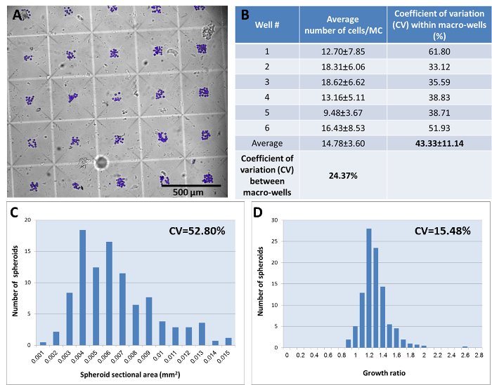
The unique HMCA imaging plate is used for the invasion assay of 3D tumor spheroids. The entire assay, beginning with the spheroid formation and ending with the invasion process and additional manipulations, is performed within the same plate. For the spheroid formation, HeLa cells are loaded into the array basin and settle in the hydrogel MCs by gravity. The hydrogel MCs, which have non-adherent/low attachment characteristics, facilitate the cell-cell interaction and the formation of 3D tumor spheroids. Figure 2A illustrates the cells settled in the MCs, following the use of 150 x 103 cells/mL loading solution (i.e., ~16 cells per MC calculated value). It is clear that the occupancy of cells per MC is not evenly distributed through the array, and the average obtained statistic distribution is 14.78 ± 3.60 cells per MC. The table in Figure 2B summarizes the cell distribution per MC for the whole HMCA plate. The average coefficient of variation (CV) of the cell distribution within a macro-well is 43.33%, while between the macro-wells it is 24.37%. The differences in cell occupancy are crucial and directly dictate the size of spheroids formed and their homogeneity throughout the plate. In order to reduce/minimize the variability created by the number of cells per MC, the analysis of the results is performed at single-element resolution. The plots in Figure 2C-D illustrate the size (sectional area) distribution of 3-day spheroids. It is clearly exemplified in Figure 2D that calculating the growth ratio of each spheroid (sectional area at day 3/day 2) has a more homogeneous distribution than the absolute size distribution (Figure 2C), yielding a CV of 15.48% and 52.80%, respectively. Spheroid diameter distribution of 3-day spheroids yields a CV of 24.52% and the growth ratio (diameter at day3/day2) is 7.45%. These CV values are similar to17 or higher than18 other reports attaining cell loading by gravity. In order to eliminate the measured parameter variance resulting from the variability in the initial seeded cell number per MC, it is preferable to normalize the selected parameters to the initial cell number or to any other measured parameter of the same object, such that each spheroid has its internal control. This approach could be easily applied by tracking the object on the HMCA imaging plate.
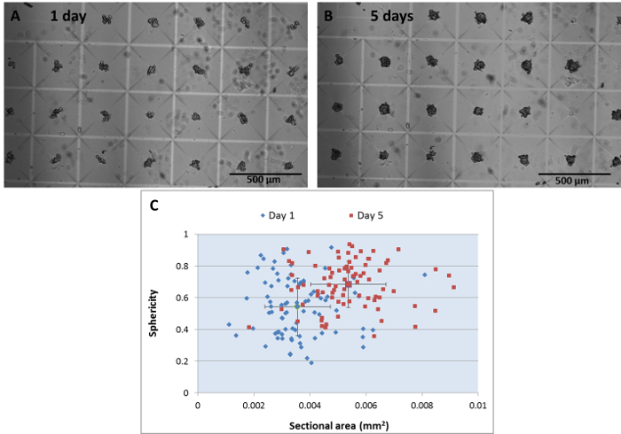
The process of spheroid formation and growth could be easily followed on the HMCA imaging plate. Figure 3A-B shows a BF image of one region on the HMCA imaging plate containing 24 h HeLa cell aggregates and the respective image of mature, 5-day 3D multicellular objects, which are becoming more spherical and denser. It is clearly shown that most objects retain their location during the 5-day incubation period. The analysis of shape (sphericity) and size (sectional area) during the spheroid formation is presented in Figure 3C. The scatter plot demonstrates the increases in both parameters from day 1 to day 5; 0.544 ±0.020 a.u. to 0.684± 0.016 a.u. for sphericity (p < 0.05) and 0.00356± 0.00013 mm2 to 0.00538 ± 0.00015 mm2 for sectional area (p < 0.05), respectively. While 24-h aggregates are small and have non-regular shape, the respective 5-day spheroids are bigger and acquire spherical form.
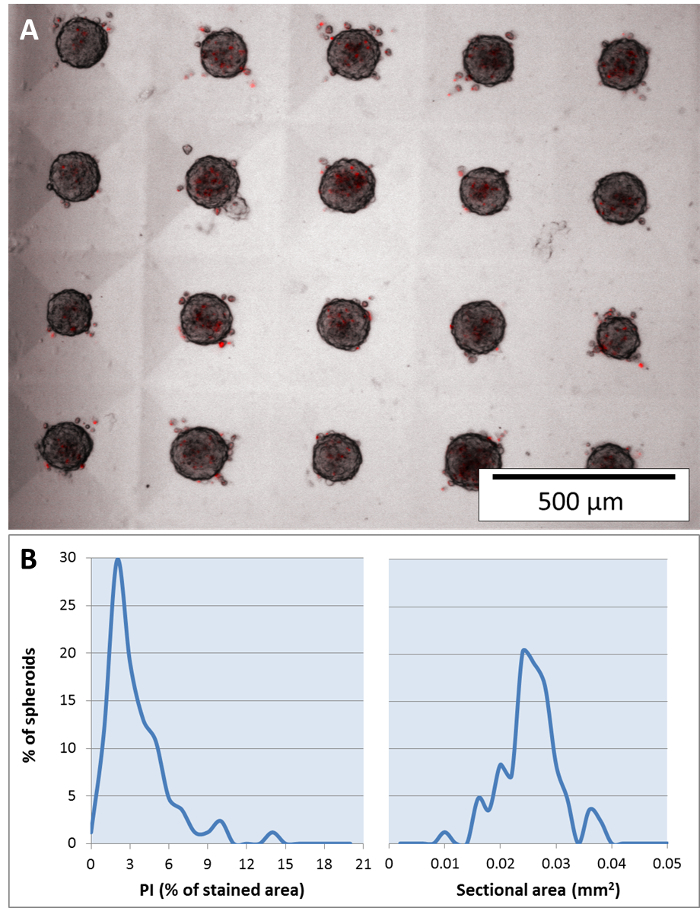
The detection of spheroid cell viability is executed by using low concentration PI for staining19 which circumvents the need for dye washing. PI penetrates the cell membrane and then intercalates into the DNA of non-viable cells. Figure 4A shows 5-day HeLa spheroids stained with PI (in red). Analysis of the percentage of red area (representing dead cells) out of each spheroid sectional area is summarized in Figure 4B. The histogram shows that 85% of spheroid population has a maximal value of 5% red stained area and the average is 3.01 ± 2.34 % (left histogram). Sectional area of spheroids (right histogram) shows a normal distribution with average of 0.02447 ± 0.00487 mm2.
After producing 3-day mature HeLa spheroids, the invasion assay is performed within the HMCA imaging plate. The effect of variables, such as ECM composition, inhibitors and activators, on the 3D tumor spheroid invasion process could be examined. For invasion assay performance, the medium is gently removed and replaced with ECM solution pipette over the spheroids into the MC array basin. After the full gelation of the ECM solution, complete medium is added into the macro-well. (1) In order to examine the influence of HA on the HeLa spheroid spontaneous invasion process, the spheroids were covered with collagen and HA mixture solution (Figure 5A) and compared to those covered with collagen only solution (Figure 5C), and BF images were acquired right after ECM gelation (t = 0 h). The kinetic of invasion process was followed by imaging the same regions every 5 h for a period of 63 h. After 50 h of incubation, the spheroids embedded in collagen and HA (Figure 5B) showed lower cell dispersion into the surrounding ECM as compared to the spheroids embedded in collagen only (Figure 5D). The analysis of the invasion area kinetic over time, for 99 spheroids at single-spheroid resolution is summarized in Figure 5E. Figure 5E plots the mean/average invasion area over time of the two groups, and clearly demonstrates that the addition of HA to collagen inhibits the cell dispersion out of the spheroid, resulting in smaller invasion areas. The average of the slopes resulting from linear regression adjustment curves for each of the spheroids embedded in collagen (0.001973 ± 0.000894 mm2/h) as compared to collagen and HA solution (0.001410 ± 0.000941 mm2/h) are significantly different (p = 0.003, t-test: two-sample assuming equal variances). (2) In order to examine the influence of Fisetin (a bioactive flavonoid found in several fruits and vegetables which shows cytostatic and migrastatic activities by acting on several molecular targets including phosphatidylinositol 3-kinase (PI3K)/Akt/c-Jun N-terminal kinases (JNK) signaling and Wnt/β-catenin signaling downregulates matrix metalloproteinases (MMPs) and others20) on HeLa spheroid spontaneous invasion process, increasing concentrations of the drug were added to the complete medium and BF images were acquired at t = 0 (Figure 6A) and 24 h later (Figure 6B-C). As demonstrated, 10 µM of Fisetin (Figure 6C) inhibits the dispersion of cells around the spheroids as compared to non-treated HeLa spheroids (Figure 6B). The invasion area analysis of a dose response experiment (Figure 6D) exhibits significant inhibition at 10-40 µM of Fisetin (p < 0.003), attaining saturation at the concentration of 10 µM and higher. (3) It has been shown that NO, at a nano-molar level, contributes to a more aggressive breast cancer phenotype by stimulating tumor expansion and migration16. In order to examine the influence of NO on the collective invasion process of MCF7 spheroids embedded in collagen, 1 µM of diethylenetriamine/nitric oxide donor (DETA/NO) was added to the complete culture medium and BF images were acquired at t = 0 and t = 20 h. Dramatic changes in the morphology and locations of 3D spheroids during exposure to NO donor are evident (Figure 7A-B). The spheroids lose their sphericity and become more elongated acquiring amoeboid migratory phenotype. Concomitantly, enhanced translocation of the spheroids within the surrounding collagen matrix was observed (Figure 7C). The average elongation value significantly increased from 1.305 ± 0.193 a.u. to 1.477 ± 0.298 a.u., (p < 0.0006). The average migration distance measured for the same spheroids was significantly extended, 0.0788 ± 0.0575 mm and 0.3164 ± 0.3365 mm in the absence and in the presence of DETA/NO, respectively (p < 4 x 10⁻⁶).
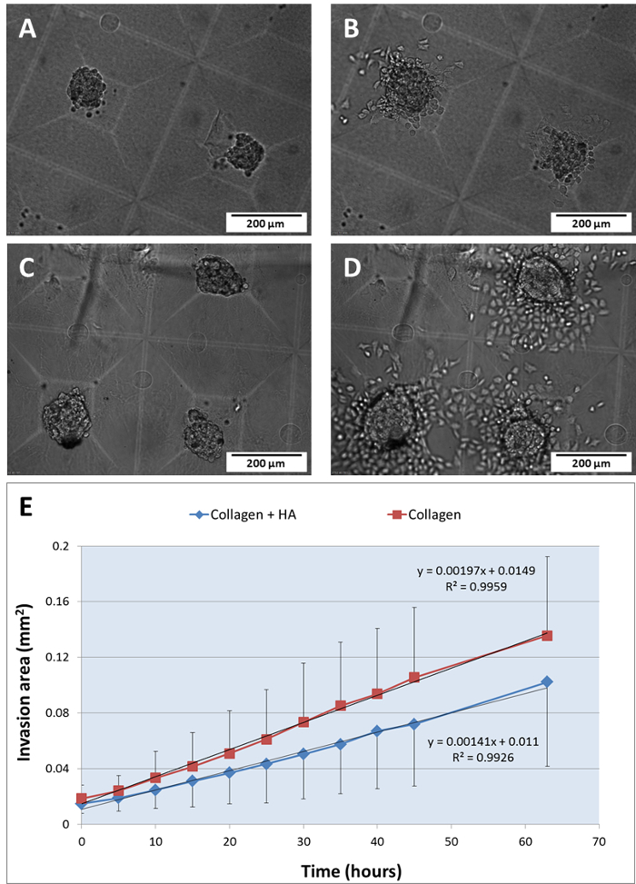
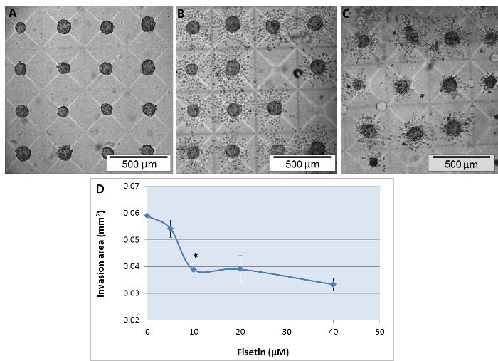
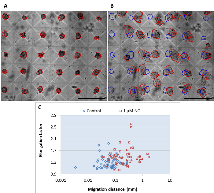
Image analysis of the spheroid invasion was achieved by semi-automatic in-house MATLAB software. The acquired time lapse images of spheroid formation and invasion within the HMCA consists of numerous spheroids in one image (4-6 spheroids at 10X magnification and 25-30 spheroids at 4X magnification). The analysis of spheroid formation, growth and invasion was concomitantly performed on all spheroids in the image. The key parameters extracted for spheroid invasion are presented in Figure 8A, which shows a representative image segmentation of 4 spheroids at a single time point (t = 16 h). The main invasion area defined by a red border, as well as the separated cells which disengaged and dispersed around it (indicated by black arrows), were tracked and numbered for each spheroid over time. Spheroid size before invasion at t = 0 is defined by a blue border. The mean/average invasion distance from spheroid center of mass to the invasion area circumference including separated cells is calculated from the encircled red segmentation and indicated by yellow arrows. Data extracted from this time-lapse experiment is summarized in Figure 8B-D. Figure 8B exhibits the elevation of the mean invasion distance from each spheroid center over time. Figure 8C exhibits the elevation of the total invasion area in each of the spheroids over time (including the main invasion area and separated/disengaged-cell area). Figure 8D1-4 shows the magnitude of separated-cell area compared to the total invasion area of each spheroid (over time). The cumulative number of disengaged cells is 33, 7, 4 and 5 for spheroids #1, #2, #3 and #4, respectively. The analysis of cumulative numbers of disengaged cells over 20 h of invasion obtained from 126 HeLa spheroids embedded in collagen is shown in Figure 8E. It is demonstrated here that there is a vast distribution in the number of disengaged cells in the examined population and the average value is 12.3 ± 12.8 cells.
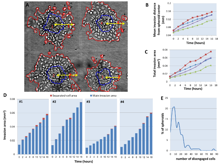
Figure 1: The HMCA imaging plate. (A) Image of one macro-well embossed with HMCA. (B) A cross section of one MC within the HMCA imaging plate. Please click here to view a larger version of this figure.
Figure 2: Homogeneity of the cell distribution and spheroid growth ratio in the HMCA imaging plate. (A) An overlay of BF and fluorescent images of the HMCA loaded with HeLa cells pre-stained with Hoechst 33342 1 µg/mL (loading concentration 150 x 103 cells per mL). Images were acquired right after the cell settlement in the MC. Image magnification 4X, Scale bar = 500 µm. (B) The table summarizes the distribution of HeLa cells within the HMCA-6-well imaging plate. The cells were counted from up to 90 MC/macro-well. The results are presented as mean ± standard deviation (SD), CV (SD/mean100) is calculated within and between the macro-wells. (C) Distribution histogram of the sectional area of 3 day spheroids, n = 418, determined from BF images. (D) Distribution histogram of the spheroid growth ratio (sectional area at day 3/day 2). Growth ratio is calculated at single-element resolution for each of the 418 spheroids. Please click here to view a larger version of this figure.
Figure 3: Tracking spheroid formation in the HMCA imaging plate. BF image of HeLa cells (loading concentration 120 x 103 cells per mL) incubated in the HMCA for 1 day (A) and 5 days (B). Image magnification 4X, Scale bar = 500 μm. (C) Scatter plot of 3D object sphericity as a function of its sectional area, after 1 day (blue diamonds) and 5 days (brown squares) of incubation post cell loading. Each marker represents the analyzed data from a single spheroid, n = 83. Please click here to view a larger version of this figure.
Figure 4: Detection of cell viability in mature spheroids. An overlay of BF and fluorescent images of 5 day spheroids (loading concentration 360 x 103 cells per mL) stained with PI 0.25 µg/mL (A). Image magnification 4X, Scale bar = 500 µm. (B) Distribution histogram of the percent of PI area relative to the sectional area of the spheroid (left panel) and distribution histogram of sectional area (right panel), n = 84. Percent of PI area is calculated at single-element resolution for each of the 84 spheroids. Please click here to view a larger version of this figure.
Figure 5: Influence of ECM composition on spheroid invasion process. BF images of 3 day HeLa spheroids embedded in a mixture of 3 mg/mL collagen and 20 µg/mL HA (A) and 3 mg/mL collagen (C), at t = 0 h and after 50 h of incubation (B) and (D), respectively. Image magnification 10X, Scale bar = 200 µm. The HMCA imaging plate was loaded onto the stage of the inverted microscope equipped with incubator. Images were acquired every 5 h and the kinetic analysis is presented in plot (E), n = 99. Each curve represents the mean ± SD of invasion area increase over time, for collagen and HA (blue diamonds) and for collagen only (brown squares). Average linear regression curve and its equation and R-squared value are indicated above the curves. Please click here to view a larger version of this figure.
Figure 6: Fisetin inhibits spontaneous invasion of HeLa spheroids. BF images of 3 day HeLa spheroids, embedded in a mixture of 3 mg/mL collagen (A) at t = 0 and then, 24 h after addition of 0 µM (B) and 10 µM Fisetin (C) to the complete culture medium. Image magnification 4X, Scale bar = 500 µm. Analysis of invasion area for each spheroid at end point (t = 24 h) is presented in plot (D), n = 488. The curve represents mean ± SD of invasion area as a function of 0-40 µM Fisetin. Fisetin treatment significantly inhibits the invasion at 10 µM (P = 4.65 x 10⁻⁶), 20 µM (P = 0.0021) and 40 µM (P = 4.86 x 10⁻⁸), using t-test: two-sample assuming equal variances. Please click here to view a larger version of this figure.
Figure 7: NO induces collective invasion in MCF-7 breast cancer spheroids. BF images of 2 day MCF-7 breast cancer spheroids, embedded in collagen (A) at (t = 0) and (B) after 20 h exposure to 1 µM DETA/NO. Spheroid ROI segmentation is defined by red border, overlaid and numbered in red on BF images A and B. ROIs defined by blue border, overlaid on BF image B represent spheroid size and location at t = 0. Magnification 4X, Scale bar = 500 µm. (C) A scatter plot of the correlation between elongation factor and migration distance of individual breast cancer spheroids upon the exposure to 1 µM DETA/NO (brown squares) as compared to control (blue diamonds) at t = 20 h, n = 54. Please click here to view a larger version of this figure.
Figure 8: HeLa cell spontaneous invasion image analysis. BF images of 3 day HeLa spheroids, 16 h after embedding in collagen (A). Magnification 10X. Spheroid invasion area and disengaged cells are defined by red border, spheroid size at t = 0 is defined by blue border, mean invasion distance from spheroid center of mass is indicated by yellow arrows and disengaged cells are indicated by black arrows. Plot the increase over time of the mean invasion distance from spheroid center of mass (B) and total invasion area (C). The curves represent spheroid #1 (blue diamonds), spheroid #2 (brown squares), spheroid #3 (green triangles) and spheroid #4 (purple Xs). (D) Bar chart of the main (blue) and separated cell (brown) invasion area increase over time. (E) Distribution histogram of the cumulative number of separated cells per spheroid during 20 h of invasion process, n = 126. Please click here to view a larger version of this figure.
Discussion
It is well documented that living organisms, characterized by their complex 3D multicellular organization are quite distinct from the commonly used 2D monolayer cultured cells, emphasizing the crucial need to use cellular models which better mimic the functions and processes of the living organism for drug screening. Recently, multicellular spheroids, organotypic cultures, organoids and organs-on-a-chip have been introduced8 for the use in standardized drug discovery. However, the 3D multicellular model's great complexity significantly jeopardizes its robustness, parallelization and data analysis which are crucial for assay efficiency.
Quantitative evaluation of invasion capacity typically measures the movement of cells through hydrogel materials. In order to measure the tumor invasion using traditional micro-well plates, large numbers of cancer cells are seeded in round bottom plates and forced to aggregate by centrifugation21,22. These plates restrict cell/spheroid interaction in adjoining wells, while the round bottom obstructs the optical quality and complicates image acquisition. In other methods, individual cells randomly encapsulated within the hydrogel, grow and function in a 3D environment but do not necessarily develop into mature spheroids23,24. Moreover, complicated procedures for cell positioning within hydrogel are required, like magnetic force-based cell patterning25 or two-photon laser irradiation of bioactive hydrogels26.
The HMCA-based technology presented herein proves to be advantageous over the above methods: cell positioning, spontaneous aggregation and creation of spheroids from few dispersed cells can be easily achieved, enabling the use of valuable limited cellular sample (e.g., cancer stem-like cells or primary cells derived from patient specimens). The system has control over both the nature of the cells that compose the spheroids as well as over their exact spatial location during long term experiments. In addition, the flat bottom of the MC facilitates the generation of numerous spheroids on the same focal plan, hence rapid illumination and image acquisition of large areas via a wide field microscope is possible, eliminating the need for complicated time-consuming confocal microscopy. The system is easy to handle and its practicality feasible. By applying simple operational procedures, we achieved high occupancy of spheroid populations in which approximately 50% of the spheroids have comparable size and a reliable analysis of cancer cell invasion capacity. In addition, the effect of drugs on invasion capacity can be analyzed simultaneously with their cytostatic and/or cytotoxic effects by using high-content analysis approach together with HMCA device cultured with numerous spheroids. Moreover, in the HMCA, all cellular elements share the same space and medium, making it possible to investigate spheroid-spheroid interaction which is usually mediated via cell-secreted cytokines, chemokines, hormones and the ECM27. This cross-talk facilitates the survival and the function of individual cells/small cell clusters in macro-well volume.
A critical step in the execution of the protocol is the addition of ECM mixture on top of the spheroids and validating its proper polymerization. The spheroids will not show migratory behavior even if they are embedded within ECM, unless assembly and cross-linking occur, and appropriate collagen fibers are formed. The collagen fibers can be observed by BF illumination, and we advise checking the plate under a microscope to confirm the creation of collagen fibers at the end of this phase. Since the number of spheroids is dependent on initial cell concentration and the percent of occupied MCs, the array should be checked after initial cell loading, and if cell occupancy is not optimal, re-seeding of the same array may be performed. Indeed, the size and geometry of the HMCA described herein were designed to accommodate relatively small cell clusters (up to 150 µm in diameter). This could be considered a limitation since designing a new type of array will be necessary for analyzing cell migration from larger cell structures.
The current platform utilizes minimal cell number and small reagent volume, while at the same time providing a large sample size (thousands of spheroids per plate). In order to analyze 12 different compounds for anti-metastatic activity, 2 single 6-well HMCA based plates would be required, yielding the results from about 5,000 spheroids, while at least fifty 96-well plates would be needed to achieve the same outcomes. The ability to analyze the migration at individual-object resolution in the HMCA provides a high level of statistical robustness and accuracy, enabling the study of structural and functional invasion heterogeneity in numerous spheroids.
This study uniquely demonstrates the collective invasion of breast cancer spheroid populations upon the exposure to DETA/NO. The cell clusters of MCF7 cells show amoeboid migratory phenotype, and quantitative changes in the morphology and location of each spheroid can be automatically attained. To the best of our knowledge, this is the first arrayed system that facilitates monitoring and analysis of collective invasion in numerous 3D structures. By analyzing the relative directions and the invasion distance for each spheroid, it is possible to study the mutual interaction between spheroids within the population. Additionally, the established influence of extracellular microenvironment factors on cancer cell behavior28 is illustrated here. Among these factors, the stiffness and composition of the microenvironment has been shown to strongly influence cell migration. HMCA technology provides a defined, biomimetic, in vitro platform, in which these properties of the ECM can be easily accessed and controlled. The stiffness of pure collagen type I hydrogel at the concentration of 3 mg/mL which was used in this study, is reported to be approximately 50-600 Pa29,30,31 and the addition of HA (20 µg/mL; 0.4 wt %) did not change the stiffness of the hydrogel significantly32,33. Thus, the suppressive effect of medium molecular weight (MMW)-HA on the invasion of 3D HeLa spheroids which was demonstrated here is not due to stiffness changes. These results are in agreement with previous studies which showed a bimodal effect of HA on cancer cell invasion with high dependency on HA molecular weight34,35,36,37.
Future applications of the methods include side by side multi cell type culturing of tumor and stromal cells in different regions within the macro-well, and retrieval of specific spheroids for downstream molecular analysis.
Disclosures
The authors declare that they have no competing financial interests.
Acknowledgments
This work is supported by the bequest of Moshe Shimon and Judith Weisbrodt.
References
- Guan X. Cancer metastases: challenges and opportunities. Acta pharmaceutica Sinica. B. 2015;5(5):402–418. doi: 10.1016/j.apsb.2015.07.005. [DOI] [PMC free article] [PubMed] [Google Scholar]
- Sapudom J, et al. The phenotype of cancer cell invasion controlled by fibril diameter and pore size of 3D collagen networks. Biomaterials. 2015;52:367–375. doi: 10.1016/j.biomaterials.2015.02.022. [DOI] [PubMed] [Google Scholar]
- Portillo-Lara R, Annabi N. Microengineered cancer-on-a-chip platforms to study the metastatic microenvironment. Lab on a chip. 2016;16(21):4063–4081. doi: 10.1039/c6lc00718j. [DOI] [PubMed] [Google Scholar]
- Gkountela S, Aceto N. Stem-like features of cancer cells on their way to metastasis. Biology Direct. 2016;11(1):33. doi: 10.1186/s13062-016-0135-4. [DOI] [PMC free article] [PubMed] [Google Scholar]
- Kramer N, et al. In vitro cell migration and invasion assays. Mutation Research/Reviews in Mutation Research. 2013;752(1):10–24. doi: 10.1016/j.mrrev.2012.08.001. [DOI] [PubMed] [Google Scholar]
- Guzman A, Sánchez Alemany V, Nguyen Y, Zhang CR, Kaufman LJ. A novel 3D in vitro metastasis model elucidates differential invasive strategies during and after breaching basement membrane. Biomaterials. 2017;115:19–29. doi: 10.1016/j.biomaterials.2016.11.014. [DOI] [PubMed] [Google Scholar]
- Lee E, Song H-HG, Chen CS. Biomimetic on-a-chip platforms for studying cancer metastasis. Current opinion in chemical engineering. 2016;11:20–27. doi: 10.1016/j.coche.2015.12.001. [DOI] [PMC free article] [PubMed] [Google Scholar]
- Mittler F, Obeïd P, Rulina AV, Haguet V, Gidrol X, Balakirev MY. High-Content Monitoring of Drug Effects in a 3D Spheroid Model. Frontiers in Oncology. 2017;7:293. doi: 10.3389/fonc.2017.00293. [DOI] [PMC free article] [PubMed] [Google Scholar]
- Evensen NA, et al. Development of a High-Throughput Three-Dimensional Invasion Assay for Anti-Cancer Drug Discovery. PLoS ONE. 2013;8(12):e82811. doi: 10.1371/journal.pone.0082811. [DOI] [PMC free article] [PubMed] [Google Scholar]
- Aw Yong KM, Li Z, Merajver SD, Fu J. Tracking the tumor invasion front using long-term fluidic tumoroid culture. Scientific Reports. 2017;7(1):10784. doi: 10.1038/s41598-017-10874-1. [DOI] [PMC free article] [PubMed] [Google Scholar]
- Mi S, et al. Microfluidic co-culture system for cancer migratory analysis and anti-metastatic drugs screening. Scientific Reports. 2016;6(1):35544. doi: 10.1038/srep35544. [DOI] [PMC free article] [PubMed] [Google Scholar]
- Chung S, Sudo R, Mack PJ, Wan C-R, Vickerman V, Kamm RD. Cell migration into scaffolds under co-culture conditions in a microfluidic platform. Lab on a chip. 2009;9(2):269–275. doi: 10.1039/b807585a. [DOI] [PubMed] [Google Scholar]
- Krakhmal NV, Zavyalova MV, Denisov EV, Vtorushin SV, Perelmuter VM. Cancer Invasion: Patterns and Mechanisms. Acta naturae. 2015;7(2):17–28. [PMC free article] [PubMed] [Google Scholar]
- Lintz M, Muñoz A, Reinhart-King CA. The Mechanics of Single Cell and Collective Migration of Tumor Cells. Journal of Biomechanical Engineering. 2017;139(2):21005. doi: 10.1115/1.4035121. [DOI] [PMC free article] [PubMed] [Google Scholar]
- Afrimzon E, et al. Hydrogel microstructure live-cell array for multiplexed analyses of cancer stem cells, tumor heterogeneity and differential drug response at single-element resolution. Lab on a Chip. 2016;16(6):1047–1062. doi: 10.1039/c6lc00014b. [DOI] [PubMed] [Google Scholar]
- Shafran Y, et al. Nitric oxide is cytoprotective to breast cancer spheroids vulnerable to estrogen-induced apoptosis. Oncotarget. 2017;8(65):108890–108911. doi: 10.18632/oncotarget.21610. [DOI] [PMC free article] [PubMed] [Google Scholar]
- Sato H, Idiris A, Miwa T, Kumagai H. Microfabric Vessels for Embryoid Body Formation and Rapid Differentiation of Pluripotent Stem Cells. Scientific Reports. 2016;6(1):31063. doi: 10.1038/srep31063. [DOI] [PMC free article] [PubMed] [Google Scholar]
- Lee K, et al. Gravity-oriented microfluidic device for uniform and massive cell spheroid formation. Biomicrofluidics. 2012;6(1):14114. doi: 10.1063/1.3687409. [DOI] [PMC free article] [PubMed] [Google Scholar]
- Zaretsky I, et al. Monitoring the dynamics of primary T cell activation and differentiation using long term live cell imaging in microwell arrays. Lab on a Chip. 2012;12(23):5007. doi: 10.1039/c2lc40808b. [DOI] [PubMed] [Google Scholar]
- Khan N, Syed DN, Ahmad N, Mukhtar H. Fisetin: a dietary antioxidant for health promotion. Antioxidants & redox signaling. 2013;19(2):151–162. doi: 10.1089/ars.2012.4901. [DOI] [PMC free article] [PubMed] [Google Scholar]
- Lee GH, et al. Networked concave microwell arrays for constructing 3D cell spheroids. Biofabrication. 2017;10(1):15001. doi: 10.1088/1758-5090/aa9876. [DOI] [PubMed] [Google Scholar]
- Vinci M, Box C, Eccles SA. Three-dimensional (3D) tumor spheroid invasion assay. Journal of visualized experiments: JoVE. 2015. p. e52686. [DOI] [PMC free article] [PubMed]
- Toh Y-C, Raja A, Yu H, van Noort D. A 3D Microfluidic Model to Recapitulate Cancer Cell Migration and Invasion. Bioengineering. 2018;5(2):29. doi: 10.3390/bioengineering5020029. [DOI] [PMC free article] [PubMed] [Google Scholar]
- Sugimoto M, Kitagawa Y, Yamada M, Yajima Y, Utoh R, Seki M. Micropassage-embedding composite hydrogel fibers enable quantitative evaluation of cancer cell invasion under 3D coculture conditions. Lab on a Chip. 2018;18(9):1378–1387. doi: 10.1039/c7lc01280b. [DOI] [PubMed] [Google Scholar]
- Yamamoto S, Hotta MM, Okochi M, Honda H. Effect of Vascular Formed Endothelial Cell Network on the Invasive Capacity of Melanoma Using the In Vitro 3D Co-Culture Patterning Model. PLoS ONE. 2014;9(7):e103502. doi: 10.1371/journal.pone.0103502. [DOI] [PMC free article] [PubMed] [Google Scholar]
- Lee S-H, Moon JJ, West JL. Three-dimensional micropatterning of bioactive hydrogels via two-photon laser scanning photolithography for guided 3D cell migration. Biomaterials. 2008;29(20):2962–2968. doi: 10.1016/j.biomaterials.2008.04.004. [DOI] [PMC free article] [PubMed] [Google Scholar]
- Gschwind A, Zwick E, Prenzel N, Leserer M, Ullrich A. Cell communication networks: epidermal growth factor receptor transactivation as the paradigm for interreceptor signal transmission. Oncogene. 2001;20(13):1594–1600. doi: 10.1038/sj.onc.1204192. [DOI] [PubMed] [Google Scholar]
- Jiang K, Dong C, Xu Y, Wang L. Microfluidic-based biomimetic models for life science research. RSC Advances. 2016;6(32):26863–26873. [Google Scholar]
- Mason BN, Starchenko A, Williams RM, Bonassar LJ, Reinhart-King CA. Tuning three-dimensional collagen matrix stiffness independently of collagen concentration modulates endothelial cell behavior. Acta biomaterialia. 2013;9(1):4635–4644. doi: 10.1016/j.actbio.2012.08.007. [DOI] [PMC free article] [PubMed] [Google Scholar]
- Raub CB, Putnam AJ, Tromberg BJ, George SC. Predicting bulk mechanical properties of cellularized collagen gels using multiphoton microscopy. Acta Biomaterialia. 2010;6(12):4657–4665. doi: 10.1016/j.actbio.2010.07.004. [DOI] [PMC free article] [PubMed] [Google Scholar]
- Paszek MJ, et al. Tensional homeostasis and the malignant phenotype. Cancer Cell. 2005;8(3):241–254. doi: 10.1016/j.ccr.2005.08.010. [DOI] [PubMed] [Google Scholar]
- Rao SS, DeJesus J, Short AR, Otero JJ, Sarkar A, Winter JO. Glioblastoma Behaviors in Three-Dimensional Collagen-Hyaluronan Composite Hydrogels. ACS Applied Materials & Interfaces. 2013;5(19):9276–9284. doi: 10.1021/am402097j. [DOI] [PMC free article] [PubMed] [Google Scholar]
- Kreger ST, Voytik-Harbin SL. Hyaluronan concentration within a 3D collagen matrix modulates matrix viscoelasticity, but not fibroblast response. Matrix Biology. 2009;28(6):336–346. doi: 10.1016/j.matbio.2009.05.001. [DOI] [PMC free article] [PubMed] [Google Scholar]
- Chanmee T, Ontong P, Itano N. Hyaluronan: A modulator of the tumor microenvironment. Cancer Letters. 2016;375(1):20–30. doi: 10.1016/j.canlet.2016.02.031. [DOI] [PubMed] [Google Scholar]
- Zhao Y, et al. Modulating Three-Dimensional Microenvironment with Hyaluronan of Different Molecular Weights Alters Breast Cancer Cell Invasion Behavior. ACS Applied Materials & Interfaces. 2017;9(11):9327–9338. doi: 10.1021/acsami.6b15187. [DOI] [PubMed] [Google Scholar]
- Wu M, et al. A novel role of low molecular weight hyaluronan in breast cancer metastasis. The FASEB Journal. 2015;29(4):1290–1298. doi: 10.1096/fj.14-259978. [DOI] [PubMed] [Google Scholar]
- Fisher GJ. Cancer resistance, high molecular weight hyaluronic acid, and longevity. Journal of cell communication and signaling. 2015;9(1):91–92. doi: 10.1007/s12079-015-0278-6. [DOI] [PMC free article] [PubMed] [Google Scholar]


