Abstract
A series of solid and macroporous N-doped carbon nanofibers composed of Fe3C nanoparticles (named as solid Fe3C/N-C NFs, solid Fe3C/N-C NFs-1, solid Fe3C/N-C NFs-2, macroporous Fe3C/N-C NFs, macroporous Fe3C/N-C NFs-1 and macroporous Fe3C/N-C NFs-2, respectively) were prepared through carbonization of as-electrospun nanofiber precursors. The results show that the magnetic Fe3C nanoparticles (NPs) dispersed homogeneously on the N-doped carbon fibers; as-prepared six materials exhibit excellent microwave absorption with a lower filler content in comparison with other magnetic carbon hybrid nanocomposites in related literatures. Particularly, the solid Fe3C/N-C NFs have an optimal reflection loss value (RL) of −33.4 dB at 7.6 GHz. For solid Fe3C/N-C NFs-2, the effective absorption bandwidth (EAB) at RL value below −10 dB can be up to 6.2 GHz at 2 mm. The macroporous Fe3C/N-C NFs have a broadband absorption area of 4.8 GHz at 3 mm. The EAB can be obtained in the 3.6–18.0 GHz frequency for the thickness of absorber layer between 2 and 6 mm. These Fe3C–based nanocomposites can be promising as lightweight, effective and low-metal content microwave absorption materials in 1–18 GHz.
Introduction
Following rapid development of electronic science and technology, widespread use of electronic devices in wireless communications, high-frequency circuit components and other related fields1–3. Considerable efforts have been put to prepare the effective electromagnetic (EM) samples due to its application in the military stealth technology4–6. In recent years, with the increasing attention on the prevention and control of electromagnetic pollution and the increasing requirements of military weapons, microwave absorbing samples with a low thickness, light density, high reflection loss at a wide frequency range and corresponding stealth technology are urgently needed7–9. And a number of studies have endeavored to the development of such materials10,11. For example, the flower-like CuS hollow materials were successfully prepared by a simple solvothermal procedure. This material can reach a lowest RL value of −31.5 dB with 30 wt% filler loading3. The Ni−CNT nanocomposites obtained the lowest RL values (−30.0 dB) at 2.0 mm thickness10. The CNFs/Fe absorbers exhibited super-duper EM wave absorbing ability on the basis of a lowest RL value (−67.5 dB) with merely 5 wt% filler loading11. Among these microwave-absorbing materials, carbon-based composite microwave-absorbing materials comprising of carbon and magnetic particles have been attracting increasing attention, including Fe3O4 multi-walled carbon nanotube (CNTs)9, Fe3C/CNT nanocomposites12 and porous Co/CNTs13. It is worth mentioning that our group prepared the cobalt/N-doped carbon nanocomposites with two morphologies using electrospinning and annealing methods14. The solid Co/N-doped carbon nanocomposites show a strong absorbing property of −24.5 dB at 3 mm with 10 wt% filler loadings. Because these materials not only have large EM losses, which can effectively improve EM wave absorption, but also can overcome the disadvantages of magnetic components with a high density13–17. The Fe3C nanoparticles possess satisfactory stability and outstanding magnetic properties18–20. Some studies have shown that the combination of Fe3C and carbon nanofibers can significantly improve the microwave absorption performance21. In order to meet the requirements of absorbing materials including light density, thin thickness, and high reflection loss at a wide frequency range, we have prepared the macroporous Fe3C/N-doped carbon nanofibers with a novel macroporous structure. The experimental results suggested that the macroporous Fe3C/N-doped carbon nanofibers were endowed with a lighter weight and a broader bandwidth contrasted to the solid Fe3C/N-doped carbon nanofibers. And the effective microwave absorption of macroporous Fe3C/N-doped carbon nanocomposites can be obtained in the 3.6–18.0 GHz frequency range. At the same time, we also prepared the solid Fe3C/N-doped carbon nanocomposites, which exhibit superior microwave absorbability with a small RL value of −34.9 dB. The Fe3C/N-doped carbon composite nanofibers achieve a significant advancement in EM wave absorbing ability at the same 10 wt% filler content compared with the Co/N-doped carbon composite nanofibers14. This may be caused by the unique magnetic properties of Fe3C nanoparticles and the better impedance matching effect between Fe3C and carbon nanofibers13,18. In recent years, the electrospinning technology has become one of the popular techniques in fabricating nanofibers, because it is a simple and mature technology that can be applied on a large scale22,23. For instance, carbon fibers consist of Fe3O4 particles were prepared by electrospinning techniques. The sample reached the minimum RL value of −44.0 dB24. Park et al. synthesized Ni–Fe composite carbon fibers by electrospinning process and the materials showed good electromagnetic wave absorbability25.
In this work, a series of solid and macroporous Fe3C/N-doped carbon hybrid nanocomposites have been obtained by carbonizing as-spun polyacrylonitrile (PAN)-based nanofiber precursors, which were synthesized by spinning a PAN/DMF (N, N-dimethyl formamide) solution containing iron acetylacetonate. The six nanocomposites with 10 wt% filler loading showed an exceedingly good microwave absorption property. The as-prepared lightweight magnetic carbon hybrid nanocomposites will be valuable in different EM absorbing areas due to their superior EM absorption performance.
Results and Discussion
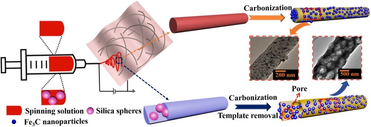
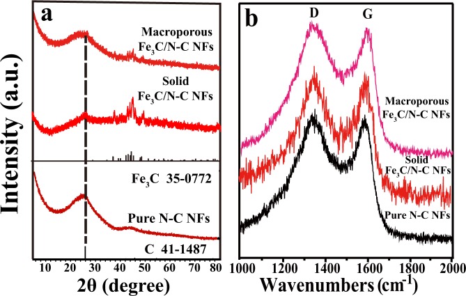
Figure 1 illustrates the preparation process of solid and macroporous Fe3C/N-doped carbon nanofibers by using electrospinning and calcination treatment. As shown in Fig. 1, the precursor nanofibers were fabricated using electrospinning method11. According to the literature21,26,27, in the heating process of the tube furnace, the polyacrylonitrile in the precursor fiber decomposes at 250–300 °C. The main decomposition products are hydrogen cyanide, ammonia and carbon, etc., however, the fiber morphology remains. Iron acetylacetonate starts to decompose into iron oxide at 280 °C. These Fe3C particles are distributed on the surface and inside of the nanofiber. As the temperature increases, the iron oxide reacts with carbon to form Fe3C nanoparticles, then the final sample of N-doped carbon nanofibers composed of Fe3C nanoparticles was produced28,29. The crystallographic features of the synthesized representative products were examined by XRD and Raman spectrometer (Fig. 2). In Fig. 2a, the peak at 2θ = 26.5° match with XRD patterns of the standard graphite carbon (JCPDS No. 41–1487)30,31. Other obvious diffraction peaks at 37.8°, 39.9°, 40.8°, 43.0°, 43.8°, 44.7°, 45.1°, 46.0°, 48.7° and 49.3° can be indexed to the (021), (200), (120), (121), (210), (022), (103), (211), (113) and (122) planes of Fe3C phase (JCPDS No. 75–0910), respectively, revealing that the Fe3C nanoparticles and nanocrystalline graphite are successfully synthesized by the carbonization method32,33. In the Raman spectra depicted in Fig. 2, two broad peaks at 1342 cm−1 and 1580 cm−1 correspond to the D band and G band from carbon. As is known to all, the ratios of ID/IG indicate the carbon disorder degree34,35. In Fig. 2b, we calculated the value of ID/IG to be 1.08:1 for solid Fe3C/N-doped carbon nanocomposites, 1.05:1 for macroporous Fe3C/N-doped carbon nanocomposites and 1.03:1 for pure N-doped carbon nanofibers, respectively. It implies that the disorder degree of the carbon in our materials has greatly increased compared with pure N-doped carbon nanofibers. Moreover, the carbon with plenty of defects can be considered as effective polarization center under electromagnetic field36.
Figure 1.
Schematic illustration of the synthesis of the two Fe3C/N-doped carbon nanocomposites.
Figure 2.
(a) XRD patterns and (b) Raman spectra of the as-obtained two representative Fe3C/N-C nanofibers and pure N-C nanofibers.
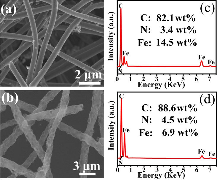
The SEM images (Fig. S1a,b) show the typical morphology of the as-obtained materials. The lengths of these two representative nanofibers could beyond several micrometers. The average diameters of solid Fe3C/N-C nanofibers are 500 nm, whereas the average diameters of macroporous Fe3C/N-C nanofibers are 1 μm (Fig. 3a,b). Their component contents are measured by EDS analysis (Fig. 3c,d). The results reveal the occurrence of C, N and Fe elements in as-synthesized two composites. For solid Fe3C/N-doped carbon nanofibers, the respective C, N and Fe mass fractions are 82.1%, 3.4% and 14.5%, while in the macroporous Fe3C/N-doped carbon nanofibers, the respective C, N and Fe mass fractions are 88.6%, 4.5% and 6.9%. The EDX mapping images and EDS spectra of solid Fe3C/N-doped carbon NFs-1, solid Fe3C/N-doped carbon NFs-2, macroporous Fe3C/N-doped carbon NFs-1 and macroporous Fe3C/N-doped carbon NFs-2 are shown in Fig. S2. For solid Fe3C/N-C NFs-1, the respective C, N and Fe mass fractions are 95.7%, 0.5% and 3.8%. As for solid Fe3C/N-C NFs-2, the respective C, N and Fe mass fractions are 80.6%, 4.4% and 15.0%. For macroporous Fe3C/N-C NFs-1, the respective C, N and Fe mass fractions are 90.0%, 4.8% and 5.2%. For macroporous Fe3C/N-C NFs-2, the respective C, N and Fe mass fractions are 86.6%, 5.0% and 8.4%. For the as-prepared solid and macroporous Fe3C/N-doped carbon nanofibers, as the amount of iron acetylacetonate of the spinning solution increases, the iron content of the final products also increases.
Figure 3.
(a,b) SEM images, (c,d) EDS spectra of the representative Fe3C/N-doped carbon nanocomposites with two structures, respectively.
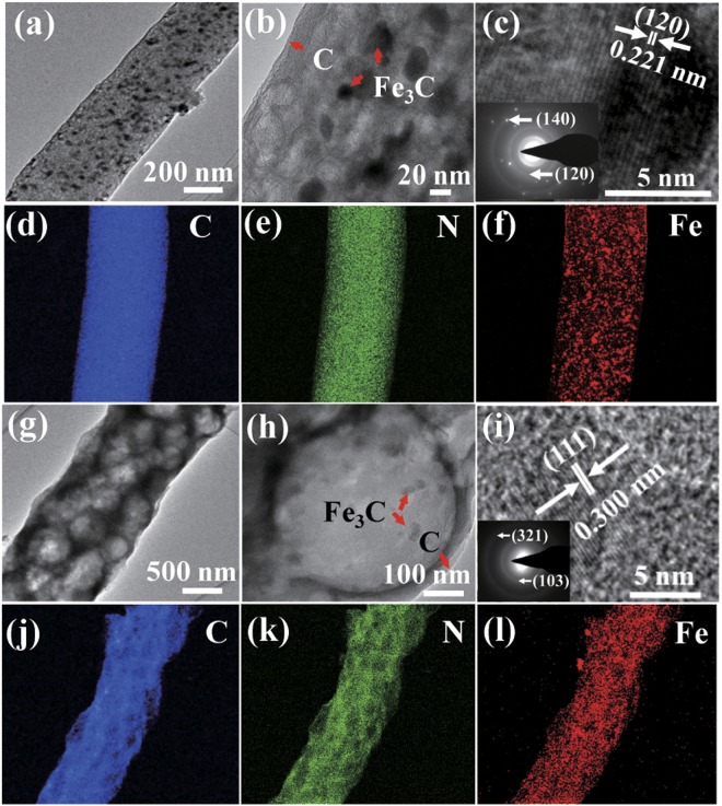
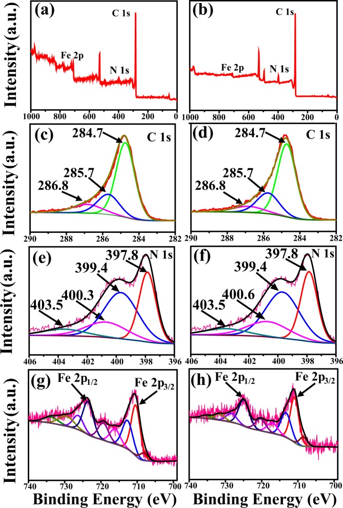
Figure 4 shows typical TEM photographs and EDX mapping images. It is obvious that numerous Fe3C NPs are uniformly distributed in the two prepared materials (Fig. 4a,g). Further, the particle sizes of the Fe3C NPs ranged from 20 to 50 nm (Fig. 4b,h). Moreover, the Fe3C NPs in the solid Fe3C/N-doped carbon nanofibers present a lattice spacing of 0.221 nm between adjacent lattice, corresponding to the (120) lattice plane (Fig. 4c), indicating a high crystallinity. The elemental mappings (Fig. 4d–f) reveal the uniform distribution of Fe3C nanoparticles throughout the nanofibers. Furthermore, the existence of C, N and Fe in the structure is further demonstrated by the peaks of N 1s, C 1s, and Fe 2p observed in Fig. 5. The HRTEM images in Fig. 4g,h, the TEM and STEM images in Fig. S1c,d demonstrate that the macroporous Fe3C/N-doped carbon nanofibers have a pore size of around 500 nm. In Fig. 4i, the lattice distance is 0.300 nm, corresponding to the (111) diffraction peak of Fe3C37. The inset of Fig. 4i displays a selected area electron diffraction (SAED) pattern and the clear diffraction rings represent the (321) and (103) planes of the Fe3C nanoparticles. Moreover, the EDX mapping results confirm that Fe3C NPs are decorated in the macroporous Fe3C/N-doped carbon nanofibers (Fig. 4j–l).
Figure 4.
Morphologies and elemental mapping images of the representative Fe3C/N-doped carbon nanocomposites with two structures: (a,b,g,h) TEM images, (c,i) HRTEM images, the insets of (c,i) corresponding SAED pattern, (d–f,j–l) EDX mapping images.
Figure 5.
XPS spectra of (a,b) Survey scans, (c,d) C 1s spectrum, (e,f) N 1s spectrum, (g,h) Fe2p spectrum of the representative Fe3C/N-doped carbon nanocomposites with two structures, respectively.
Figure 5 shows the survey spectra of the two representative nanocomposites. In the survey XPS spectra (Fig. 5a,b), the XPS peaks for C 1s, N 1s, and Fe 2p indicate the existence of these elements in these synthesized nanomaterials. Figure 5c,d represent the XPS spectra of C 1s for as-fabricated nanofibers. The C 1s spectrum includes three peaks that can be indexed to C-C at around 285.7 eV, C-N at around 284.7 eV and C-O at around 286.8 eV, respectively38,39. Figure 5e,f display N 1s spectra of the as-fabricated products. The N 1s spectrum include four different nitrogen atoms: pyridinic N (397.8 eV), pyrrolic N (399.4 eV), quaternary N (400.3 and 400.6 eV), and oxidized N (403.5 eV)33. The peaks at 708.5 eV is due to Fe3C. The other peaks shown in the spectra of Fe 2p in Fig. 5g could be divided into two pairs of peaks at around 710.4 and 724.4 eV, which represent Fe 2p3/2 and Fe 2p1/2, respectively40,41. This confirms the existences of Fe3C in as obtained materials. As shown in Fig. 5h, in the macroporous Fe3C/N-C NFs, the peaks at 708.5 eV correspond to Fe3C, and the other two major peaks at around 710.6 and 725.0 eV represent the Fe 2p3/2 and Fe 2p1/2, respectively.
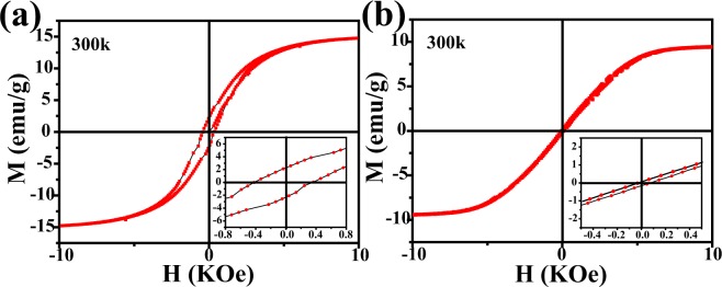
Figure 6 illustrates the magnetic hysteresis loops of as synthetized Fe3C/N-C nanofibers materials measured at room temperature. From Fig. 6, it is not difficult to find that the two samples exhibit typical ferromagnetic properties at 300 K42,43. The saturation magnetization of the solid Fe3C/N-doped carbon nanocomposites reaches 14.8 emu/g and 9.4 emu/g for macroporous Fe3C/N-doped carbon nanocomposites. This phenomenon can be related to the higher iron contents for solid Fe3C/N-doped carbon nanocomposites44. As shown in Fig. 3c,d, the Fe mass fraction of the solid Fe3C/N-doped carbon hybrid nanocomposites (14.5%) is larger than that in macroporous Fe3C/N-doped carbon hybrid nanocomposites (6.9%). The specific surface area (SSA) of pure N-doped carbon nanofibers, solid and macroporous Fe3C/N-doped carbon nanofibers are 28.1, 144.3 and 30.6 m2 g−1, respectively (Fig. S3). As shown in Fig. S3, the two samples display IV N2 adsorption isothermals, indicating that mesoporous structures in these materials. The SSA of the obtained materials was computed by Brunauer-Emmett-Teller method. Due to the limitations of the method, the 500 nm macropores is too large to be represented in the specific surface area data, so the macropores has no remarkable impact on the SSA of the macroporous Fe3C/N-doped carbon nanocomposites. The Fe3C/N-doped carbon hybrid nanocomposites have a larger SSA compared with the pure N-doped nanofibers, which indicates that the mass fraction of iron plays a major role in the specific surface area of these materials45,46. Besides, the iron mass fraction of this macropores nanofibers is smaller than the nanofibers with solid structure47,48, so the SSA of the macroporous nanocomposites is smaller than the solid nanocomposites. As is known to all, coercivity force is considered as a momentous parameter to evaluating the magnetic performance. The EM wave absorbers possess a high coercivity force value might result in a resonance effect49. In addition, the coercivity force value is closely bound up with the metal content. As a result, a high metal content may cause a high coercivity50. Herein, the solid nanofibers with the higher iron content are endowed with the higher coercive force of 421 Oe, whereas the coercivity force of macroporous nanofibers are 46 Oe.
Figure 6.
Hysteresis loops of (a) solid Fe3C/N-doped carbon nanocomposites and (b) macroporous Fe3C/N-doped carbon nanocomposites at 300 K.
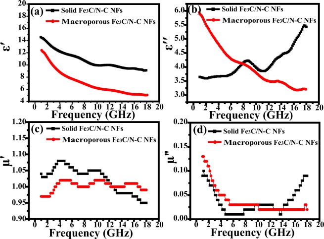
Figure 7a,b denote the curve of the real and imaginary parts (ε′ and ε″) of the complex permittivity as a function of frequency. For the two Fe3C/N-doped carbon hybrid nanocomposites, the ε′ values decrease from 14.6 to 9.12 and 12.6 to 5.2 in 1–18 GHz, respectively. The ε″ value of macroporous Fe3C/N-C NFs decreases from 6.0 to 3.2, while the ε″ values of solid Fe3C/N-C NFs increases from 3.65 to 5.43 and exhibits a peak in the 6.0–11.0 GHz ranges, which reflects a relatively high dielectric loss51. In contrast to the macroporous nanocomposites, the solid nanocomposites have a larger ε′ value, suggesting that higher appropriate conductivity is obtained. As shown in Fig. 7c,d, the real (μ′) and imaginary (μ″) part of the complex permeability for two samples remains constant, so we suppose that the complex permittivity may play an important role in the EM absorbing ability of the two nanofibers.
Figure 7.
(a) ε′, (b) ε″, (c) μ′ and (d) μ″ of the two representative Fe3C/N-doped carbon nanofibers with 10 wt% filler content.
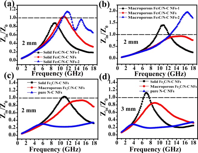
In order to investigate the main determinant for the as fabricate solid and macroporous nanofibers, we measured the dielectric dissipation factors tan dε = ε″/ε′ and magnetic loss tangent tan dμ = μ″/μ′ of the two nanocomposites at 2 mm, respectively (Fig. 8). For the solid Fe3C/N-doped carbon nanofibers, the tan dε and tan dμ curves have similar trends with the ε″ and μ″ curves (Fig. 7b,d), suggesting both dielectric loss and magnetic loss have an effect on the EM wave absorbing performance of the solid nanofibers, or, impedance matching51,52. Nevertheless, we didn’t see similar results for macroporous Fe3C/N-doped carbon nanofibers. On the other hand, we also calculated Z = |Zin/Z0| of as-prepared samples as shown in Fig. 9. Figure 9a displays the normalized characteristic impedance of three as-prepared solid Fe3C/N-doped carbon nanofibers at 2.0 mm. The experimental results show that the Z values of the solid Fe3C/N-C NFs and solid Fe3C/N-C NFs-2 are approximately 1.0 (The nearer to 1.0 for Z, the better the impedance matching properties), suggesting the rather good impedance matching properties53. Figure 9b displays the impedance matching performance of three as-prepared macroporous Fe3C/N-doped carbon nanofibers at 2.0 mm. It is obvious that the macroporous Fe3C/N-C NFs have more appropriate impedance matching properties compared with the other two macroporous Fe3C/N-doped carbon nanocomposites. Besides, we also compare the impedance matching performance of the two representative Fe3C/N-C nanofibers and pure N-C nanofibers with the thickness of 2 mm and 3 mm (Fig. 9c,d). The Z values of solid Fe3C/N-C NFs are close to 1, which represents a remarkable impedance matching performance. Especially, for solid Fe3C/N-C nanofibers, the appropriate components, synergistic effect of conductive N-doped carbon nanofibers and higher composition of magnetic Fe3C nanoparticles are propitious to their outstanding impedance matching properties. The Z values of macroporous Fe3C/N-C NFs are far away from 1.0, indicating a relatively worse impedance matching properties. The Z values of pure N-C nanofibers are near to 0, revealing nearly none impedance matching properties. Thus we speculate that the solid Fe3C/N-C NFs have better impedance matching properties which can lead leading to the excellent microwave-wave absorbing ability.
Figure 8.
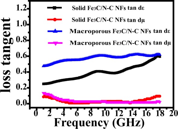
tan dε and tan dμ for the two representative Fe3C/N-doped carbon nanofibers with 10 wt% doping content.
Figure 9.
Calculated modulus of normalized characteristic impedance of (a) three as-obtained solid Fe3C/N-doped carbon nanocomposites at 2 mm (b) three as-synthesized macroporous Fe3C/N-doped carbon nanocomposites at 2 mm (c) the representative two Fe3C/N-C nanocomposites and pure N-C nanofibers at 2 mm (d) the representative two Fe3C/N-C nanocomposites and pure N-C nanofibers at 3 mm.
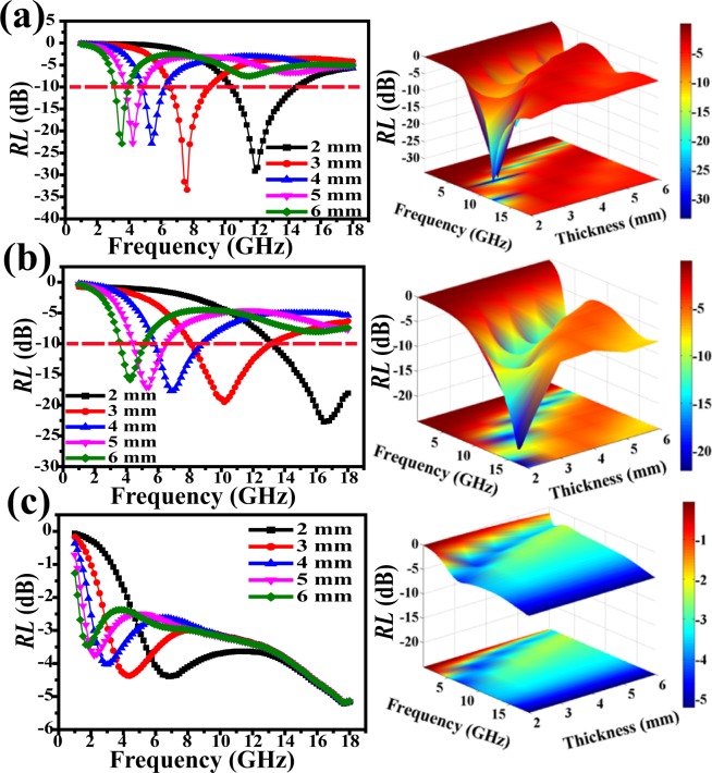
The RL values were evaluated via measuring relative complex permittivity (εr = ε′ − jε″) and permeability (μr = μ′ − jμ″) based off of equations (1) and (2). The EM absorption property of solid Fe3C/N-doped carbon nanofibers with 10 wt% filler loading is shown in Fig. 10a. The respective optimal microwave absorption is achieved at 11.9 GHz for −29.1 dB (2 mm), 7.6 GHz for −33.4 dB (3 mm) and 5.4 GHz for −22.8 dB (4 mm), respectively. The EAB is 4.1 GHz (10.4–14.5 GHz) at 2.0 mm. In Fig. 10b, the macroporous Fe3C/N-doped carbon nanofibers with 10 wt% nanofiber loading shows an optimal RL value of −22.1 dB. The microwave absorbing bandwidths with RL lower than −10 dB are 4.8 GHz (8.2–13.0 GHz) at 3.0 mm. Apparently, the solid Fe3C/N-doped carbon nanocomposites present the optimal reflection loss value. Perhaps it is because the solid Fe3C/N-doped carbon nanofibers have the larger coercivity force and higher iron content54,55. Moreover, the proper impedance matching also plays a major role in its superior EM wave absorbing properties. As shown in Fig. 10c, the lowest RL value of the pure N-doped carbon nanofibers with 10 wt% doping amount is unable to achieve −10 dB at 2.0–6.0 mm. The EM absorbing ability of other two solid Fe3C/N-doped carbon nanofibers and two macroporous Fe3C/N-doped carbon nanofibers are shown in Fig. S4. In Fig. S4a, the optimal frequency value of solid Fe3C/N-C NFs-1 can reach −34.4 dB at 3.0 mm. It is worth mentioning that solid Fe3C/N-C NFs-2 with 6 mm possess an optimal RLmin of −34.9 dB. The effective absorption bandwidth can reach 6.2 GHz across 11.8–18.0 GHz (Fig. S4c). The macroporous Fe3C/N-C NFs-1 displays the optimal EM absorption of −32.8 dB among the three macroporous Fe3C/N-doped carbon nanocomposites (Fig. S4b). The macroporous Fe3C/N-C NFs-2 displays the strongest RL value of −15.0 dB (Fig. S4d). Table 1 concludes the EM-wave absorbing ability of these Fe3C/N-doped carbon composite nanofibers. Table 2 shows that the present solid Fe3C/N-C NFs-2 and macroporous Fe3C/N-C NFs exhibits the outstanding EM wave absorbing ability among the related Fe3C-based materials with the smallest fiber loadings. For example, Fe-Fe3C/C microspheres with 25 wt% doping amount gained an optimal RL of −18.8 dB12. The Fe3C/graphitic carbon with 70 wt% doping amount loading achieved the optimal RL value (−26 dB) at 2.0 mm56. The Fe3C/C nanocapsules with 40 wt% doping amount obtained the strongest RL of −38 dB and the EAB was only 2.0 GHz57. It is exhilarating to observe that these Fe3C/N-doped carbon nanocomposites possess an enhanced EM wave absorbing performance with the smallest fiber loadings58.
Figure 10.
Simulated curves of EM wave reflection loss of (a) solid Fe3C/N-doped carbon nanocomposites (b) macroporous Fe3C/N-doped carbon nanocomposites, (c) pure N-doped carbon nanofibers with 10 wt% filler content.
Table 1.
Microwave absorbing ability of the as-prepared materials in 1–18 GHz.
| Samples | Optimal RL Values (dB) | Matching Thickness (mm) | RL Values at 2 mm (dB) | Effective Bandwidth at 2 mm (GHz) |
|---|---|---|---|---|
| Solid Fe3C/N-C NFs | −33.4 | 3.0 | −29.2 | 4.1 |
| Solid Fe3C/N-C NFs-1 | −34.4 | 3.0 | −19.4 | 2.4 |
| Solid Fe3C/N-C NFs-2 | −34.9 | 6.0 | −31.3 | 6.2 |
| Macroporous Fe3C/N-C NFs | −22.1 | 2.0 | −22.1 | 4.6 |
| Macroporous Fe3C/N-C NFs-1 | −32.8 | 5.0 | −17.2 | 2.5 |
| Macroporous Fe3C/N-C NFs-2 | −15.0 | 6.0 | −11.5 | 0.8 |
Table 2.
Typical Fe-based materials for EM wave absorption reported in related literatures.
| Samples | Mass Ratio (wt%) | Optimal RL Values (dB) | Matching Thickness (mm) | Frequency Range RL ≤ −10 dB (GHz) | Ref |
|---|---|---|---|---|---|
| Fe3C/HCNTs | 50 | −21.5 | 2.0 | 4.0 | 12 |
| C/Fe3O4 nanorods | 55 | −27.9 | 2.0 | 5.8 | 17 |
| Fe–C nanofibers | 50 | −44.0 | 3.0 | 1.7 | 24 |
| Fe-Fe3C/C microspheres | 25 | −18.8 | 1.5 | 4.0 | 56 |
| Fe3C/graphitic carbon | 70 | −26.0 | 2.0 | 4.0 | 57 |
| Fe3C/C nanocapsules | 40 | −38.0 | 1.9 | 2.0 | 58 |
| Laminated RGO/Fe3O4 | 30 | −26.4 | 4.0 | 2.0 | 60 |
| hollow Fe3O4−Fe/G | 18 | −30.5 | 2.0 | 6.2 | 62 |
| Solid Fe3C/N-C NFs-2 | 10 | −34.9 | 6.0 | 6.2 | This work |
| Macroporous Fe3C/N-C NFs | 10 | −22.1 | 2.0 | 4.8 | This work |
Conclusions
In summary, solid and macroporous Fe3C/N-doped carbon nanocomposites have been successfully obtained by coupling electrospinning with heat treatment in an argon atmosphere. The nanocomposites possess superior microwave absorption capability at a lower doping content (10 wt%). The solid Fe3C/N-C NFs display the optimal RL value of −33.4 dB at 3 mm. The lower RL value can be attribute to the appropriate impedance matching, which can be achieved by changing the formation of the absorber and Fe3C content. The solid Fe3C/N-C NFs-2 present an optimal RLmin of −34.9 dB with the widest EAB of 6.2 GHz. The minimum RL value of the macroporous Fe3C/N-C NFs-1 is up to −32.8 dB at 4.2 GHz. The RL value of the macroporous Fe3C/N-C NFs exceeds −10 dB in the 3.6–18.0 GHz for the thickness of absorber layer between 2 and 6 mm. These Fe3C/N-doped carbon hybrid nanofibers are promising full-band EM-wave absorbers with low density and less doped metal.
Methods
All chemicals were analytical pure and used without any pre-purification. Polyacrylonitrile (PAN, Mw = 150,000) and Iron acetylacetonate (97%) were purchased from Sigma-Aldrich Company. N, N-dimethyl formamide (DMF, 99.5%), Ethyl orthosilicate (TEOS), ammonium hydroxide (NH3·H2O, 25%), ethanol (C2H5OH, 99.7%) and sodium hydroxide (NaOH, 96%) were obtained from Beijing Chemical Reagent Co. Ltd.
Preparation of solid Fe3C/N-doped carbon nanofibers
Typically, 1.0 g PAN and 0.8 g iron acetylacetonate were dissolved in 10 mL DMF, followed by slowly mixing under vigorously stirring for 24 hours. Next, the precursor solution was put in a syringe for spinning. The applied positive high voltage was maintained at 12 kV and the negative high voltage was maintained at −4 kV. The receiving distance was 15 cm and the feeding rate was controlled at 0.1 mL/min. The as-spun fibers were calcined at 280 °C for 3 h and then heated up to 800 °C with a heating rate of 1 °C/min in an Ar atmosphere. The sample obtained was recorded as solid Fe3C/N-C NFs. Besides, the solid Fe3C/N-doped carbon nanofibers with the different amount of iron acetylacetonate (0.6 and 1.0 mg, respectively) were prepared and named as solid Fe3C/N-C NFs-1 and solid Fe3C/N-C NFs-2, respectively.
Preparation of macroporous Fe3C/N-doped carbon nanofibers
The template (silica microspheres) was synthesized according to the description by Stöber et al.11. The macroporous Fe3C/N-doped carbon nanocomposites were prepared using the similar synthetic process with 1.2 g previously synthesized silica template in the spinning dope. The obtained precursor fibers were placed in sodium hydroxide solution and stirred for 2 h to remove the template, followed by washing with deionized water and desiccation. The sample gained was recorded as macroporous Fe3C/N-C NFs. Besides, the macroporous Fe3C/N-doped carbon nanofibers with the different amount of iron acetylacetonate (0.6 and 1.0 mg, respectively) were prepared and named as macroporous Fe3C/N-C NFs-1 and macroporous Fe3C/N-C NFs-2, respectively.
Preparation of pure N-doped carbon nanofibers
The pure N-C NFs were obtained by the similar process as solid Fe3C/N-doped carbon nanofibers synthesization without adding metal salt precursors.
Materials characterization
The three solid Fe3C/N-doped carbon nanofibers and three macroporous Fe3C/ N-doped carbon nanofibers have almost the same morphology, structure and magnetic performance, therefore the solid Fe3C/N-C NFs and macroporous Fe3C/N-C NFs are selected as the representative in each group to describe its morphology, microstructure and magnetic performance in details. The structure of the products was carried out by X-ray diffraction (XRD). Field-emission scanning electron microscopy (FESEM, Hitachi SU-8010), high-resolution transmission electron microscopy (HRTEM, JEM-2010), scanning transmission electron microscope (STEM), energy-dispersive X-ray spectroscopy (EDX) and energy-dispersive spectrometer (EDS) analysis were used to characterize the morphology, microstructures and element content of the representative solid and macroporous nanofibers. X-ray photoelectron spectroscopy (XPS) spectra were characterized by ESCALAB 250Xi spectrometer (Thermo Fisher). Raman spectra were measured by a Raman spectrometer. The hysteresis loops were achieved by superconducting quantum interference device (SQUID-MPMS3) at room temperature.
Measurement of electromagnetic parameters and absorbing performance
The value of complex permittivity (ε′, ε″) and permeability (μ′, μ″) of the as-synthesized seven products were evaluated via a network analyzer (Model No. HP-E8362B, Agilent, frequency range 1.0 GHz to 18.0 GHz). The measurement samples were prepared by homogeneously milling the powders (10 wt%) in paraffin and then pressing them into a ring of 7.0 mm external diameter, 3.04 mm inner diameter, 2.0 mm thickness59,60. The EM-wave absorbing ability of the materials were computed by equations (1) and (2)61,62.
| 1 |
| 2 |
where d, f, c, Zin and Z0 represent the absorber thickness, microwave frequency, light velocity, input characteristic impedance and air impedance, respectively
Electronic supplementary material
Acknowledgements
Financial support from the National Natural Science Foundation of China (No. 21771024, 21421003, 51672026, 51527802, 51372020, and 51232001), Beijing Municipal Science & Technology Commission (No. Z161100002116027), National Key Research and Development Program of China (No. 2016YFA0202701).
Author Contributions
Huihui Liu and Genban Sun conceived and designed the experiments. Huihui Liu and Yajing Li fabricated the samples and conducted the measurements. Yue Zhang and Qingliang Liao contributed to measure electromagnetic absorption properties. All authors discussed the results and Huihui Liu, Mengwei Yuan, Genban Sun contributed to the manuscript preparation. All authors reviewed the manuscript.
Competing Interests
The authors declare no competing interests.
Footnotes
Publisher’s note: Springer Nature remains neutral with regard to jurisdictional claims in published maps and institutional affiliations.
Contributor Information
Genban Sun, Email: gbsun@bnu.edu.cn.
Qingliang Liao, Email: liao@ustb.edu.cn.
Yue Zhang, Email: yuezhang@ustb.edu.cn.
Electronic supplementary material
Supplementary information accompanies this paper at 10.1038/s41598-018-35078-z.
References
- 1.Zhang Y, et al. Broadband and tunable high-performance microwave absorption of an ultralight and highly compressible graphene foam. Adv. Mater. 2015;27:2049–2053. doi: 10.1002/adma.201405788. [DOI] [PubMed] [Google Scholar]
- 2.Yin X, et al. Electromagnetic properties of Si–C–N based ceramics and composites. Int. Mater. Rev. 2014;59:326–355. [Google Scholar]
- 3.Zhao B, et al. Synthesis of flower-like CuS hollow microspheres based on nanoflakes self-assembly and their microwave absorption properties. J. Mater. Chem. A. 2015;3:10345–10352. doi: 10.1039/C5TA00086F. [DOI] [Google Scholar]
- 4.Li X, et al. One-pot synthesis of CoFe2O4/graphene oxide hybrids and their conversion into FeCo/graphene hybrids for lightweight and highly efficient microwave absorber. J. Mater. Chem. A. 2015;3:5535–5546. doi: 10.1039/C4TA05718J. [DOI] [Google Scholar]
- 5.Quan B, et al. Strong electromagnetic wave response derived from the construction of dielectric/magnetic media heterostructure and multiple interfaces. ACS Appl. Mater. Interfaces. 2017;9:9964–9974. doi: 10.1021/acsami.6b15788. [DOI] [PubMed] [Google Scholar]
- 6.Faisal S, et al. Electromagnetic interference shielding with 2D transition metal carbides (MXenes) Science. 2016;353:1137–1140. doi: 10.1126/science.aag2421. [DOI] [PubMed] [Google Scholar]
- 7.Qiu S, et al. Facile synthesis of porous nickel/carbon composite microspheres with enhanced electromagnetic wave absorption by magnetic and dielectric losses. ACS Appl. Mater. Interfaces. 2016;8:20258–20266. doi: 10.1021/acsami.6b03159. [DOI] [PubMed] [Google Scholar]
- 8.Wu T, et al. Facile hydrothermal synthesis of Fe3O4/C core-shell nanorings for efficient low-frequency microwave absorption. ACS Appl. Mater. Interfaces. 2016;8:7370–7380. doi: 10.1021/acsami.6b00264. [DOI] [PubMed] [Google Scholar]
- 9.Wang Z, et al. Magnetite nanocrystals on multiwalled carbon nanotubes as a synergistic microwave absorber. J. Phys. Chem. C. 2013;117:5446–5452. doi: 10.1021/jp4000544. [DOI] [Google Scholar]
- 10.Sha L, Gao P, Wu T, Chen Y. Chemical Ni-C bonding in Ni-carbon nanotube composite by a microwave welding method and its induced high-frequency radar frequency electromagnetic wave absorption. ACS Appl. Mater. Interfaces. 2017;9:40412–40419. doi: 10.1021/acsami.7b07136. [DOI] [PubMed] [Google Scholar]
- 11.Xiang J, et al. Magnetic carbon nanofibers containing uniformly dispersed Fe/Co/Ni nanoparticles as stable and high-performance electromagnetic wave absorbers. J. Mater. Chem. A. 2014;2:16905–16914. doi: 10.1039/C4TA03732D. [DOI] [Google Scholar]
- 12.Tang H, et al. Fe3C/helical carbon nanotube hybrid: Facile synthesis and spin-induced enhancement in microwave-absorbing properties. Composites Part B. 2016;107:51–58. doi: 10.1016/j.compositesb.2016.09.003. [DOI] [Google Scholar]
- 13.Yin Y, Liu X, Wei X, Yu R, Shui J. Porous CNTs/Co composite derived from zeolitic imidazolate framework: a lightweight, ultrathin, and highly efficient electromagnetic wave absorber. ACS Appl. Mater. Interfaces. 2016;8:34686–34698. doi: 10.1021/acsami.6b12178. [DOI] [PubMed] [Google Scholar]
- 14.Liu H-H, et al. In situ preparation of Cobalt nanoparticles decorated in N-doped carbon nanofibers as excellent electromagnetic wave absorbers. ACS Appl. Mater. Interfaces. 2018;10:22591–22601. doi: 10.1021/acsami.8b05211. [DOI] [PubMed] [Google Scholar]
- 15.Feng J, et al. Interfacial interactions and synergistic effect of CoNi nanocrystals and nitrogen-doped graphene in a composite microwave absorber. Carbon. 2016;104:214–225. doi: 10.1016/j.carbon.2016.04.006. [DOI] [Google Scholar]
- 16.Wang G, et al. High densities of magnetic nanoparticles supported on graphene fabricated by atomic layer deposition and their use as efficient synergistic microwave absorbers. Nano Res. 2014;7:704–716. doi: 10.1007/s12274-014-0432-0. [DOI] [Google Scholar]
- 17.Chen Y-J, et al. Porous Fe3O4/carbon core/shell nanorods: synthesis and electromagnetic properties. J. Phys. Chem. C. 2011;115:13603–13608. doi: 10.1021/jp202473y. [DOI] [Google Scholar]
- 18.Lei X, Wang W, Ye Z, Zhao N, Yang H. High saturation magnetization of Fe3C nanoparticles synthesized by a simple route. Dyes and Pigments. 2017;139:448–452. doi: 10.1016/j.dyepig.2016.12.046. [DOI] [Google Scholar]
- 19.Jiang X, et al. Ultrathin AgPt alloy nanowires as a high-performance electrocatalyst for formic acid oxidation. Nano Res. 2017;508:462–468. [Google Scholar]
- 20.Kumar R, Sahoo B. Investigation of disorder in carbon encapsulated core-shell Fe/Fe3C nanoparticles synthesized by one-step pyrolysis. Diamond and Related Materials. 2018;90:62–71. doi: 10.1016/j.diamond.2018.10.003. [DOI] [Google Scholar]
- 21.Sun C, et al. In situ preparation of carbon/Fe3C composite nanofibers with excellent electromagnetic wave absorption properties. Composites Part A. 2017;92:33–41. doi: 10.1016/j.compositesa.2016.10.033. [DOI] [Google Scholar]
- 22.Xue H, et al. A nickel cobaltate nanoparticle-decorated hierarchical porous N-doped carbon nanofiber film as a binder-free self-supported cathode for nonaqueous Li–O2batteries. J. Mater. Chem. 2016;A4:9106–9112. doi: 10.1039/C6TA01712F. [DOI] [Google Scholar]
- 23.Huang Q, et al. One-step electrospinning of carbon nanowebs on metallic textiles for high-capacitance supercapacitor fabrics. J. Mater. Chem. A. 2016;4:6802–6808. doi: 10.1039/C5TA09309K. [DOI] [Google Scholar]
- 24.Mordina B, Kumar R, Tiwari RK, Setua DK, Sharma A. Fe3O4 nanoparticles embedded hollow mesoporous carbon nanofibers and polydimethylsiloxane-based nanocomposites as efficient microwave absorber. J. Phys. Chem. C. 2017;121:7810–7820. doi: 10.1021/acs.jpcc.6b12941. [DOI] [Google Scholar]
- 25.Park K-Y, Han J-H, Lee S-B, Yi J-W. Microwave absorbing hybrid composites containing Ni–Fe coated carbon nanofibers prepared by electroless plating. Composites Part A. 2011;42:573–578. doi: 10.1016/j.compositesa.2011.01.020. [DOI] [Google Scholar]
- 26.Kumar R, Choudhary HK, Pawar SP, Bose S, Sahoo B. Carbon encapsulated nanoscale iron/iron-carbide/graphite particles for EMI shielding and microwave absorption. Phys. Chem. Chem. Phys. 2017;19:23268–23279. doi: 10.1039/C7CP03175K. [DOI] [PubMed] [Google Scholar]
- 27.Kumar R, Sahoo B. One-step pyrolytic synthesis and growth mechanism of core–shell type Fe/Fe3C-graphite nanoparticles-embedded carbon globules. Nano-Structures & Nano-Objects. 2018;16:77–85. doi: 10.1016/j.nanoso.2018.05.005. [DOI] [Google Scholar]
- 28.Kumar R, Anupama VA, Kumaran V, Sahoo B. Effect of solvents on the structure and magnetic properties of pyrolysis derived carbon globules embedded with iron/iron carbide nanoparticles and their applications in magnetorheological fluids. Nano-Structures & Nano-Objects. 2018;16:167–173. doi: 10.1016/j.nanoso.2018.06.002. [DOI] [Google Scholar]
- 29.Kumar R, Sahoo B. Carbon nanotubes or carbon globules: Optimization of the pyrolytic synthesis parameters and study of the magnetic properties. Nano-Structures & Nano-Objects. 2018;14:131–137. doi: 10.1016/j.nanoso.2018.01.014. [DOI] [Google Scholar]
- 30.Barman BK, Nanda KK. Prussian blue as a single precursor for synthesis of Fe/Fe3C encapsulated N-doped graphitic nanostructures as bi-functional catalysts. Green Chem. 2016;18:427–432. doi: 10.1039/C5GC01405K. [DOI] [Google Scholar]
- 31.Yang W, Liu X, Yue X, Jia J, Guo S. Bamboo-like carbon nanotube/Fe3C nanoparticle hybrids and their highly efficient catalysis for oxygen reduction. J. Am. Chem. Soc. 2015;137:1436–1439. doi: 10.1021/ja5129132. [DOI] [PubMed] [Google Scholar]
- 32.Wu A, Liu D, Tong L, Yu L, Yang H. Magnetic properties of nanocrystalline Fe/Fe3C composites. CrystEngComm. 2011;13:876–882. doi: 10.1039/C0CE00328J. [DOI] [Google Scholar]
- 33.Ren G, et al. Porous core-shell Fe3C embedded N-doped carbon nanofibers as an effective electrocatalysts for oxygen reduction reaction. ACS Appl. Mater. Interfaces. 2016;8:4118–4125. doi: 10.1021/acsami.5b11786. [DOI] [PubMed] [Google Scholar]
- 34.Xia H, Wan Y, Yuan G, Fu Y, Wang X. Fe3O4/carbon core–shell nanotubes as promising anode materials for lithium-ion batteries. J. Power Sources. 2013;241:486–493. doi: 10.1016/j.jpowsour.2013.04.126. [DOI] [Google Scholar]
- 35.Sun X, Li Y. Colloidal carbon spheres and their core/shell structures with noble-metal nanoparticles. Angew. Chem. Int. Ed. 2004;43:597–601. doi: 10.1002/anie.200352386. [DOI] [PubMed] [Google Scholar]
- 36.Fang J, et al. Rice husk-based hierarchically porous carbon and magnetic particles composites for highly efficient electromagnetic wave attenuation. J. Mater. Chem. C. 2017;5:4695–4705. doi: 10.1039/C7TC00987A. [DOI] [Google Scholar]
- 37.Yang H, et al. Oxidase-mimicking activity of the nitrogen-doped Fe3C@C composites. Chem.Commun. 2017;53:3882–3885. doi: 10.1039/C7CC00610A. [DOI] [PubMed] [Google Scholar]
- 38.Kang Y, et al. Incorporate boron and nitrogen into graphene to make BCN hybrid nanosheets with enhanced microwave absorbing properties. Carbon. 2013;61:200–208. doi: 10.1016/j.carbon.2013.04.085. [DOI] [Google Scholar]
- 39.Zhang S, et al. Porous magnetic carbon sheets from biomass as an adsorbent for the fast removal of organic pollutants from aqueous solution. J. Mater. Chem. A. 2014;2:4391–4397. doi: 10.1039/C3TA14604A. [DOI] [Google Scholar]
- 40.Joshi B, et al. Supersonically blown reduced graphene oxide loaded Fe–Fe3C nanofibers for lithium ion battery anodes. J. Alloy. Compd. 2017;726:114–120. doi: 10.1016/j.jallcom.2017.07.306. [DOI] [Google Scholar]
- 41.Zhong B, Wang C, Wen G, Yu Y, Xia L. Facile fabrication of boron and nitrogen co-doped carbon@Fe2O3/Fe 3C/Fe nanoparticle decorated carbon nanotubes three-dimensional structure with excellent microwave absorption properties. Composites Part B. 2018;132:141–150. doi: 10.1016/j.compositesb.2017.09.001. [DOI] [Google Scholar]
- 42.Chen N, et al. Co7Fe3 and Co7Fe3@SiO2 nanospheres with tunable diameters for high-performance electromagnetic wave absorption. ACS Appl. Mater. Interfaces. 2017;9:21933–21941. doi: 10.1021/acsami.7b03907. [DOI] [PubMed] [Google Scholar]
- 43.Wang H, et al. Covalent interaction enhanced electromagnetic wave absorption in SiC/Co hybrid nanowires. J. Mater. Chem. A. 2015;3:6517–6525. doi: 10.1039/C5TA00303B. [DOI] [Google Scholar]
- 44.Lv H, et al. Coin-like alpha-Fe2O3@CoFe2O4 core-shell composites with excellent electromagnetic absorption performance. ACS Appl. Mater. Interfaces. 2015;7:4744–4750. doi: 10.1021/am508438s. [DOI] [PubMed] [Google Scholar]
- 45.Shen G, et al. Enhanced microwave absorption properties of N-doped ordered mesoporous carbon plated with metal Co. J. Alloy. Compd. 2016;680:553–559. doi: 10.1016/j.jallcom.2016.04.181. [DOI] [Google Scholar]
- 46.Wang N, Zhao P, Zhang Q, Yao M, Hu W. Monodisperse nickel/cobalt oxide composite hollow spheres with mesoporous shell for hybrid supercapacitor: a facile fabrication and excellent electrochemical performance. Composites Part B. 2017;113:144–151. doi: 10.1016/j.compositesb.2017.01.041. [DOI] [Google Scholar]
- 47.Cheng Y, et al. Rationally regulating complex dielectric parameters of mesoporous carbon hollow spheres to carry out efficient microwave absorption. Carbon. 2018;127:643–652. doi: 10.1016/j.carbon.2017.11.055. [DOI] [Google Scholar]
- 48.Etacheri V, Wang C, O’Connell MJ, Chan CK, Pol VG. Porous carbon sphere anodes for enhanced lithium-ion storage. J. Mater. Chem. A. 2015;3:9861–9868. doi: 10.1039/C5TA01360G. [DOI] [Google Scholar]
- 49.Ohkoshi S, et al. A millimeter-wave absorber based on gallium-substituted epsilon-iron oxide nanomagnets. Angew. Chem. Int. Ed. 2007;46:8392–8395. doi: 10.1002/anie.200703010. [DOI] [PubMed] [Google Scholar]
- 50.Herzer G. Modern soft magnets: Amorphous and nanocrystalline materials. Acta Mater. 2013;61:718–734. doi: 10.1016/j.actamat.2012.10.040. [DOI] [Google Scholar]
- 51.Liu T, Xie X, Pang Y, Kobayashi S. Co/C nanoparticles with low graphitization degree: a high performance microwave-absorbing material. J. Mater. Chem. C. 2016;4:1727–1735. doi: 10.1039/C5TC03874J. [DOI] [Google Scholar]
- 52.Wu H, Li H, Sun G, Ma S, Yang X. Synthesis, characterization and electromagnetic performance of nanocomposites of graphene with α-LiFeO2 and β-LiFe5O8. J. Mater. Chem. C. 2015;3:5457–5466. doi: 10.1039/C5TC00778J. [DOI] [Google Scholar]
- 53.Liu Y, et al. Broadband and Lightweight Microwave Absorber Constructed by in Situ Growth of Hierarchical CoFe2O4/Reduced Graphene Oxide Porous Nanocomposites. ACS Appl. Mater. Interfaces. 2018;10:13860–13868. doi: 10.1021/acsami.8b02137. [DOI] [PubMed] [Google Scholar]
- 54.Choudhary HK, et al. Mechanistic Insight into the Critical Concentration of Barium Hexaferrite and the Conductive Polymeric Phase with Respect to Synergistically Electromagnetic Interference (EMI) Shielding. Chemistry Select. 2017;2:830–841. [Google Scholar]
- 55.Choudhary HK, et al. Effect of Coral-Shaped Yttrium Iron Garnet Particles on the EMI Shielding Behaviour of Yttrium Iron Garnet-Polyaniline-Wax Composites. Chemistry Select. 2018;3:2120–2130. [Google Scholar]
- 56.Li W, et al. Fe–Fe3C/C microspheres as a lightweight microwave absorbent. RSC Adv. 2016;6:24820–24826. doi: 10.1039/C6RA02787C. [DOI] [Google Scholar]
- 57.Bateer B, et al. A novel Fe3C/graphitic carbon composite with electromagnetic wave absorption properties in the C-band. RSC Adv. 2015;5:60135–60140. doi: 10.1039/C5RA08623J. [DOI] [Google Scholar]
- 58.Tang Y, Shao Y, Yao KF, Zhong YX. Fabrication and microwave absorption properties of carbon-coated cementite nanocapsules. Nanotechnology. 2014;2:035704. doi: 10.1088/0957-4484/25/3/035704. [DOI] [PubMed] [Google Scholar]
- 59.Pan G, Zhu J, Ma S, Sun G, Yang X. Enhancing the electromagnetic performance of Co through the phase-controlled synthesis of hexagonal and cubic Co nanocrystals grown on graphene. ACS Appl. Mater. Interfaces. 2013;5:12716–12724. doi: 10.1021/am404117v. [DOI] [PubMed] [Google Scholar]
- 60.Sun X, et al. Laminated magnetic graphene with enhanced electromagnetic wave absorption properties. J. Mater. Chem. C. 2013;1:765–777. doi: 10.1039/C2TC00159D. [DOI] [Google Scholar]
- 61.Liu X, Hao C, Jiang H, Zeng M, Yu R. Hierarchical NiCo2O4/Co3O4/NiO porous composite: a lightweight electromagnetic wave absorber with tunable absorbing performance. J. Mater. Chem. C. 2017;5:3770–3778. doi: 10.1039/C6TC05167G. [DOI] [Google Scholar]
- 62.Qu B, Zhu C, Li C, Zhang X, Chen Y. Coupling hollow Fe3O4-Fe nanoparticles with graphene sheets for high-performance electromagnetic wave absorbing material. ACS Appl. Mater. Interfaces. 2016;8:3730–3735. doi: 10.1021/acsami.5b12789. [DOI] [PubMed] [Google Scholar]
Associated Data
This section collects any data citations, data availability statements, or supplementary materials included in this article.


