Abstract
Vasomotor reactivity, which is important to estimate neurogenic regulation of blood vessels in patients with different pathologies, is still assessed by occlusion plethysmography using sensors contacting the limbs. Recently we proposed a contactless approach for measuring blood flow changes during venous occlusion using imaging photoplethysmography [Kamshilin et al., Sci. Rep. 7, 464 2017]. In this work, the response of the vascular system on the occlusion was studied simultaneously by contact air-plethysmography system and remote optical system under illumination by incoherent polarized green light. A high correlation (r > 0.93) between the waveforms measured by both system was observed. Moreover, we found that the response of the optical system on the venous occlusion is uniform at the whole area of the forearm. The new optical technique is more convenient for assessment of the blood flow dynamics because it can be used for measurements in any part of the body. Method of imaging photoplethysmography is very promising for use in equipment intended for evaluation of neurogenic mechanisms of regulation of vascular blood flow.
1. Introduction
Assessment of the muscle blood flow and studying of the reactivity of blood vessels in response to various physiological impacts is an important approach for diagnosis of vasomotor regulation disorders in a wide range of patients. The well-known method of occlusive plethysmography [1] is still considered as the most appropriate for evaluation of vascular reactivity. Initially, either water- or air-filled cuff was used for plethysmography measurements, but these setups were bulky and required a well-trained operator to be implemented properly [2]. Currently, the mercury-in-rubber type of strain sensors is still widely used to measure changes of limb's circumference caused by the venous occlusion [1,3] in spite of toxicity of mercury. More advanced metal-free electromechanical sensor with inelastic but flexible plastic line spanning around the limb [4,5] was also proposed for measurements of forearm blood flow. However, all these methods require direct contact with a subject skin, which constrains their wide applications because of impossibility of measuring damaged limbs and necessity of proper selecting of the well-wrapping gauge. Several attempts to apply optical technologies based on contact photoplethysmography (PPG) to the assessment of venous blood flow were unsuccessful, as well [6–8]. Development of noncontact plethysmography systems could overcome these problems. Nakano et al. suggested assessment of venous compliance via measurements of skin-color changes nearby superficial veins caused by venous occlusion by digital color camera [9]. However, this technique has been validated only in the back of the hand.
In imaging photoplethysmography (IPPG) the subject’s skin is typically illuminated by green polarized light, and the video camera captures the live image through a cross-polarized filter attached to the lens [10–12], so it actually measures and records the quantity of the light scattered and reemitted from the dermis tissue including the shallow capillary bed located just below the epidermis. Any changes in the blood microcirculation parameters can be detected as changes in the amount of light reemitted from the skin [13,14]. Particularly, change of musculocutaneous blood flow due to venous occlusion should lead to alteration of microcirculation, as well. However, the detailed mechanism explaining how and which parameters of the capillary blood flow do result in green light intensity modulation remains unrevealed. Nevertheless, recently we demonstrated the feasibility of monitoring the changes of microcirculation in the course of venous occlusion by using IPPG system [15]. Four monochrome cameras providing all-around video recordings of subject’s forearm illuminated by green light were used in this pilot experiment. It was found that the mean light intensity reemitted from the skin is linearly diminishing immediately after the occlusion starts in the most of the arm surface. The optical waveform had the shape similar with the typical response of classical plethysmography [15]. However, no direct comparison with the classical plethysmography was done in this first experiment.
IPPG videos, besides the useful signal components reflecting the parameters of the capillary bed, also contain deviations because of the subject’s unintended movements, illumination fluctuations, and other factors. These signal components do not carry the information about the capillary bed and should be considered as noise. Typical approach to increase the signal-to-noise ratio (SNR) in IPPG is averaging when the temporal signal component is calculated as mean of the varying image pixel values over the chosen region of interest (ROI) within every frame. The averaging allows to reduce both noise components: the camera-sensor noise and the noise which appears due to unintended movements. This type of averaging was utilized for obtaining the reference signal in high-spatial-resolution IPPG [10]. However, averaging over a large area can be used only to detect the signal component that is synchronous within the entire area. If the parameters of the capillary bed vary differently at different locations of the visible skin, then the amplitude of the signal varying with every frame calculated as mean pixel values over large areas may sufficiently degrade and the information on the capillary-bed condition can be lost. To provide improvements in IPPG signal quality, other approaches were proposed. These are based on spatiotemporal filtering [16], algorithms for proper ROI selection [17], blind source separation methods [18,19] including independent component analysis for multivariate data [20] and principal component analysis [21], and motion resistant spectral peak tracking method [22]. In this research, we study the properties of the IPPG signal using matrix singular value decomposition (SVD) [23] when applying venous occlusion tests.
The aim of this work was twofold: (i) to simultaneously measure the response of classical air plethysmography (APG) and IPPG system on venous occlusion of an upper limb and (ii) analyze homogeneity of the IPPG-system response over large area of the forearm by applying advanced processing of recorded video frames.
2. Materials and methods
2.1. Four-cameras imaging system
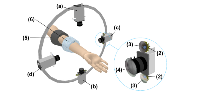
Experiments were carried out by using a custom-made IPPG system similar to that described in [15]. It consisted of four Smartek Vision GC1391MP digital cameras with Sony ICX267 CCD image sensor, and KOWA LM5NCL lenses. The cameras were installed around the forearm at the distance of 20-25 cm to provide all-round video recordings of subject’s forearm as shown in Fig. 1. Image frames with a resolution of 696 × 520 pixels were recorded at the frame rate of 30 frames per second. Two LEDs (BL-HP20APGCL-5W STAR) with the output power of 5W and wavelength of 525 nm were placed nearby each camera lens providing almost uniform illumination of the forearm’s side recorded by the respective camera (Fig. 1). Light emitted by each pair of LEDs propagates through film polarizers with parallel transmittance axes assembled ahead of each LED. The cross-polarized analyzer was installed ahead of the respective camera lens to increase SNR [12,24]. The whole setup was covered with opaque fabric to reduce the influence of the ambient light. All four cameras were controlled by a custom-made software via personal computer allowing simultaneous start of video recordings from four sides of the forearm. The frames were saved in the portable network graphics (PNG) format directly into the computer RAM to avoid problems with the bandwidth of the network connector between the camera and its processor.
Fig. 1.
Layout of the measuring setup for simultaneous recording of the vascular system reaction on the venous occlusion by IPPG and APG systems: (1) Digital cameras, (2) Illuminating green LEDs, (3) Film polarizers, (4) Cross-polarized analyzer, (5) Inflating cuff, (6) Measuring cuff of the Dohn plethysmograph; (a), (b), (c), and (d) are indexes of the video cameras.
2.2. Experimental procedure
During the experiment, the subject was in a comfortable supine position whereas his hand was in the physiological position on a support keeping the arm at the same level as the heart. The support was adjusted so that the forearm was located approximately at the same distance from each of four cameras. Venous occlusion was accomplished using inflation cuff attached to the lower third of the subject’s upper arm. Another, measuring cuff of an air plethysmograph was attached to the upper third of the forearm to measure changes of the forearm size in the course of the venous occlusion. It was custom-made plethysmograph fabricated according to design of Dohn et al. [25]. The measuring cuff consisted of a flexible inner jacket made of thin, elastic rubber and an outer stiff plastic frame. It was filled with air at ambient pressure and connected to the pressure sensor. During venous occlusion, the pressure in the cuff is increasing due to an increase in the limb volume caused by the influx of arterial blood in conditions of outflow cessation via the venous vessels. At small volume changes, the air pressure in the cuff grows up linearly in time with the inclination angle proportional to the blood flow in the tissue located distal to the occluding cuff.
Baseline conditions were recorded simultaneously by IPPG and APG systems for about 4 seconds. In the next step, the venous blood flow was suspended by fast increasing of the pressure in the occlusion cuff up to 40 mmHg and maintaining this pressure for 10 seconds. Then, the occlusion cuff was deflated and kept without pressure 10 seconds more. The occlusion cuff was inflated and deflated sequentially three times. Duration of the experiment was about one minute. During the whole test, the subject was asked to relax, avoid any movement, and keep breathing normally. All measurements were carried out in a medical laboratory at the temperature of 22 ± 2 °C.
2.3. Participants
We recruited seven volunteers (5 males, 2 females) between 26 and 64 years (42.1 ± 14.7 years). Each subject was informed about the experimental procedure and gave written consent of participation in the experiment. The study was conducted in accordance with ethical standards presented in the 2013 Declaration of Helsinki. The study plan was approved by the ethical research committee of the Almazov National Medical Research Centre prior the experiments.
2.4. Image and signal processing
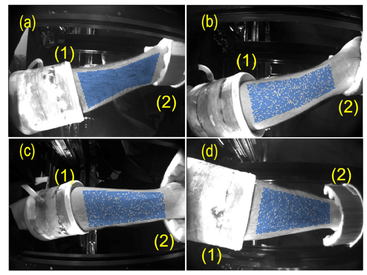
Typical set of four images of a subject’s forearm is shown in Fig. 2. Particular subject placed his hand inside the measuring setup in such a way that the images of radial and ulnar sides of the forearm were recorded by the cameras (a) and (b), respectively, whereas the cameras (c) and (d) recorded the palmar and dorsal sides of the forearm, respectively. Note that each subject has chosen the most comfortable position for his hand, thus the correspondence between the camera index and the recorded part of the forearm was different for different subjects. The measuring air-cuff and support for the hand can be also seen in each part of Fig. 2. All the frames recorded by four cameras were processed off-line by using custom software implemented in the MATLAB platform.
Fig. 2.
Images of a subject’s forearm from four digital cameras: (a) the radial side viewed by the top camera, (b) the ulnar side viewed by the bottom camera, (c) and (d) the palmar and dorsal sides viewed by the right and left cameras, respectively. The measuring air-cuff of APG system and the hand support are marked by (1) and (2), respectively. Blue points show the random choice of 2048 samples in each view of the forearm skin.
APG system includes the measuring cuff with the embedded air-pressure sensor. Its signal was sampled at 16 Hz and then filtered by Bessel low-pass filter of 4th order with the cutoff frequency of 4 Hz. The filtering was performed by filtfilt function in Matlab providing zero phase shift. Then the resulting signal was interpolated to obtain new samples at the frequency of 30 Hz to be matched with the frame rate of our video system. Since preliminary experiments revealed similarity of the PPG and classical plethysmography waveforms recorded in the course of venous occlusion [15], we synchronized APG and the mean IPPG signals off-line calculating the cross-correlation function and defining the time mismatch between them.
In this research we used SVD technique for IPPG data processing to find out the most significant temporal function which describes the time-varying modulation of the light due to venous occlusion. With arbitrarily selected images, the ROIs were chosen manually on the frames from all four cameras. ROIs were formed by polygons situated within the areas with well visible skin. To speed up the calculation and reduce the required amount of computer memory for SVD, the images have been reduced by a factor 4, and the number of spatial samples from every ROI has been chosen to be less or equal to 2048. If the number of pixels within the ROI of the reduced image exceeded this limit, the required samples within the ROI were chosen randomly (an example of the random choice is shown in Fig. 2 by blue points). After the ROIs selection, images had been read sequentially to fill either the all-cameras or joined-data matrix with elements obtained by sampling the images at distinct time of each image frame and pixel coordinates :
| (1) |
Since the recorded information includes images from multiple cameras, the position vector contains not just ordinary geometrical coordinates within an image but also the correspondent camera index.
Before calculating the SVD of the matrix , mean values and linear trends from every column of were removed. The SVD represents the signal as
| (2) |
where is the diagonal amplitude matrix consisting of singular values of the original data matrix ; and columns of the matrices and consist of left and right singular vectors of . These sets of vectors are orthonormal:
| (3) |
where is the identity matrix. Typically the computer algorithms of SVD are designed in such a way that order of columns in calculated matrices and corresponds to decreasing diagonal values of the matrix . It means that the contribution of the first columns of and is higher than the second ones, etc.
When the SVD is applied for a complete data set, i.e., when the original matrix contains values of all pixels from all frames of the video, the matrices and can be used to represent temporal principal components (PCs) and spatial distribution of their amplitudes [26]. In our analysis, we used all frames for calculations but the number of spatial samples in selected ROIs was reduced, as described above, and the SVD was applied to joined-data matrix only to obtain the common temporal PCs. To find the most variable parts in the studied images, the orthonormal columns of were used to calculate the decomposition of temporal variation of any image pixel into a sum of PCs,
| (4) |
where
| (5) |
Here, are the elements of the matrix , and is the number of frames. The coefficients of this decomposition mapped into the image space would show a spatial distribution of the amplitude of every PC. SVD is often used for principal component analysis (PCA) [26] to find correlated data and transform the data set in such a way that it allows to represent the data with the reduced amount of variables. SVD can be successfully used for detection of the most pronounced changes in the signal and association of these changes with correspondent spatial distributions. Therefore, the size of the required SVD can be diminished to a few principal components if the resulting accuracy of the signal representation (Eq. (1) is sufficient. Particularly, if one of the processes is dominating over others, the first diagonal value of the matrix will be much larger than others, and temporal variations of the process will be described by the first columns of the matrices and . Then, the first column of the matrix allows calculations of the spatial distribution of the amplitude with the dominant process.
In our experiments, PC represents temporal changes of the light intensity reemitted from the skin. According to a convention accepted by the majority of PPG researchers, changes of the light intensity are inverted in sign providing IPPG waveform to correlate positively with variations of blood pressure [13,27]. Similarly, we inverted the sign of the PCs in all our calculations.
3. Results
3.1. Comparison of IPPG and APG responses on venous occlusion
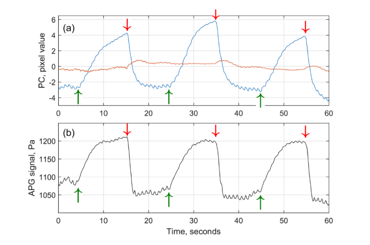
Typical response of both IPPG and APG systems on the triple venous occlusion is shown in Fig. 3. IPPG waveforms were calculated from the matrix (Eq. (1) containing the data recorded by all four cameras. The first and second PCs taken from two leftmost columns of multiplied by their respective diagonal elements of (Eq. (2) and scaled to represent the root-mean-square deviation of the light intensity in units of pixel value are shown in Fig. 3a by blue and red lines, respectively. The black line in Fig. 3b shows the APG waveform in units of the pressure.
Fig. 3.
Comparison of IPPG and APG waveforms in response to triple venous occlusion. (a) Two largest principal components calculated by SVD from the matrix of video-signals from all 4 cameras. First and second PC are shown by blue and red curves, respectively. (b) Signal from the air-cuff plethysmography (black curve). Green and red arrows show the beginning and end of each event of venous occlusion.
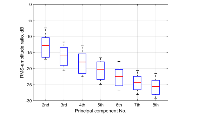
As one can see, the amplitude of the first PC is much higher than the second. A significant excess of the first PC over all other PCs was found in all 14 experiments (the sequence of triple venous occlusion was applied twice to every subject). Distribution of the root-mean-square (RMS) amplitudes of the higher PCs normalized by the RMS amplitude of the first PC among all experimental trials is shown in Fig. 4 proving that the first largest PC presents the most variable signal change in the image. It is clearly seen in Fig. 3 that the shape of the first PC is very similar to the shape of the APG waveform: (i) the beginning and end of each occlusion event are well synchronized, and (ii) small oscillations at the frequency ~1 Hz attributed with arterial blood pulsations at the heart rate are in phase in both waveforms.
Fig. 4.
RMS amplitudes of PCs from 2nd to 8th normalized by RMS amplitude of 1st PC obtained from 14 statistically independent measurements of the response on triple venous occlusion. Zero dB corresponds to the RMS of the first PC. Red horizontal lines, blue boxes, and whiskers show the mean, its standard deviation, and extreme values, respectively of the data for each PC order.
Nevertheless, some differences between these waveforms are also visible: more pronounced saturation of the APG signal after the fifth second of occlusion, and more delayed relaxation of the IPPG signal after the end of occlusion. To compare quantitatively IPPG and APG waveforms we calculated Pearson’s coefficients of correlation between these two waveforms for 14 statistically independent experiments: these coefficients vary from 0.67 to 0.95 with the median value of 0.8. Therefore, high correlation observed between responses of different systems confirms the feasibility of the contactless optical system to monitor the blood flow changes during venous occlusion.
Heartbeat-related pulsatile component of the first PC was observed in all measured subjects. As seen in Fig. 3, the amplitude of pulsations before the occlusion event is higher than at the end of occlusion in both IPPG and APG waveforms. Every occlusion is the statistically independent event. Analysis of 67 acts of venous occlusion revealed that the relative decrease of the mean pulsation amplitude measured by IPPG during last 3 s before the occlusion end in respect to that averaged during 3 s before the occlusion beginning is 43 ± 14% (Mean ± STD) with the minimal and maximal decrease of 11% and 78%, respectively. Similar decrease of the pulsation amplitude was measured by APG: 45 ± 20% with 6% in the minimum and 76% in the maximum (P = 0.44).
3.2. Mapping the response measured by IPPG system
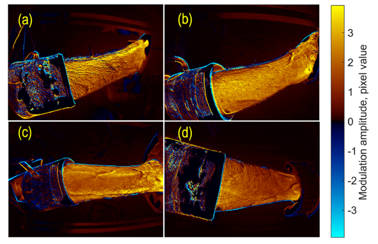
To visualize the spatial distribution of the light-intensity modulation that is synchronized with the first temporal PC, we used Eq. (5) to calculate the amplitude of this modulation in every image pixel. An example of this distribution is shown in Fig. 5 for a subject whose forearm images are shown in Fig. 2 and PCs are shown in Fig. 3(a). The modulation amplitude represents the contribution of the first PC in the light intensity changes in different image areas. The amplitude is coded in the color scale shown on the right side. The positive sign of the amplitude in Fig. 5 corresponds to the in-phase variations of light intensity in respect to the first PC (different tones of red), whereas the negative – to the counter-phase (different tones of blue).
Fig. 5.
Spatial distribution of the amplitude of the light intensity variations in time corresponding to the first PC. The radial, ulnar, palmar, and dorsal sides of the forearm are shown in panels (a), (b), (c), and (d), respectively. The color scale on the right shows the amplitude in pixel values. Red-yellow colors are associated with the positive sign for in-phase modulations with the first PC, whereas blue-cyan colors represent the negative sign or counter-phase modulation.
As one can see in Fig. 5, the light reemitted from the forearm skin is modulated in time synchronously over the entire skin area. Moreover, in all studied subjects, the considerable changes of the forearm’s image in time occur in-phase with the first PC. Similar color shades in different forearm sides assume an insignificant difference in the mean amplitude of intensity variations. For spatial distributions of the particular sample shown in Fig. 5, the normalized mean amplitude was 1.20, 1.00, 1.05, and 0.74 for radial, ulnar, palmar, and dorsal sides, respectively. Here the mean amplitude calculated for each side was normalized to the global mean from 4 sides to minimize possible physiological differences among the subjects. One can see that the amplitude map of the radial side (Fig. 5(a)) is slightly yellow than that of the dorsal side (Fig. 5(d)). However, the ratio of the mean modulation amplitude varies from one subject to another.
3.3. Comparison of responses from different cameras
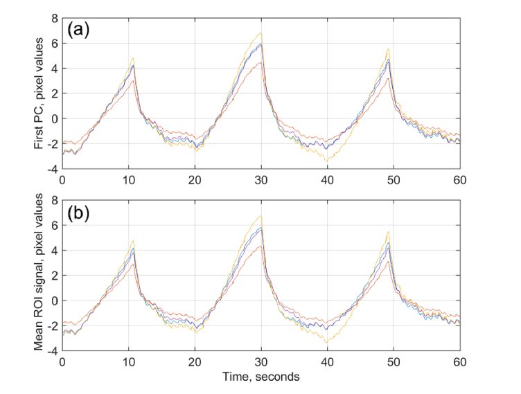
To quantitatively estimate the similarity of individual cameras response on the venous occlusion, SVD was applied independently to every ROI signals from each camera. First largest PCs marked by different colors for each camera are shown in Fig. 6(a). For comparison, the evolution of the mean pixel value spatially averaged over the same selected ROI in the data collected by different cameras are shown in Fig. 6(b) by the curves of the same color as in Fig. 6(a). It is seen that these spatially averaged signals are almost identical to the first PCs from correspondent cameras, and all of them practically coincide with the first PC calculated from the joined data of four cameras (Fig. 3(a)).
Fig. 6.
Temporal evolution of the signals from individual cameras. (a) First PCs calculated from each camera, and (b) spatially averaged signals over the selected ROIs. Yellow, magenta, blue, and brown colors correspond to the signals from cameras aimed on radial, ulnar, palmar and dorsal sides of the forearm, respectively.
The similarity of temporal signals was evaluated numerically by coefficients of correlation between the first PC from an individual camera and the first common PC obtained from joined data shown in Fig. 3(a). The Pierson coefficients were calculated among 7 subjects in 14 independent experiments and found to be between 0.974 and 0.999 with the median values of 0.997, 0.993, 0.997, and 0.998 for palmar, dorsal, radial, and ulnar sides, respectively. Likewise, the Pierson correlation between the evolution of the mean pixel value measured by the individual camera (such as shown in Fig. 6(b)) and respective first PC from all cameras were found to be very high: from 0.970 to 0.999, P < 0.001. Therefore, both SVD and averaging applied to data from a single camera can be used to calculate temporal changes of the light intensity reemitted from the forearm skin.
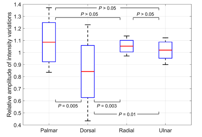
Figure 7 shows the distribution of the normalized mean amplitude of intensity modulation among the forearm’s sides in 14 experiments with triple venous occlusion. It is seen that the modulation amplitude in the dorsal side is significantly smaller than in any other forearm’s side, whereas there is no significant difference in the mean amplitude measured in palmar, radial, and ulnar sides. Thus, it is advisable to locate a single camera for monitoring the venous occlusion so that it views any forearm’s side except the dorsal.
Fig. 7.
Normalized mean amplitude of the light intensity modulation caused by triple venous occlusion as a function of the forearm’s side. Distribution of the amplitude is presented as the mean (red lines), standard deviation (boxes), and extreme values (whiskers) measured in 14 experiments for 7 subjects. Labels at the X-axis show the part of forearm viewed by a camera.
4. Discussion
4.1. Origin of light intensity modulation
The occlusion plethysmography is aimed to estimate the musculocutaneous blood flow measured as an increase of the limb volume due to arterial blood inflow in conditions of the venous outflow cessation caused by the occluding cuff [28]. APG system transfers the volume increase into the measurable change of the air pressure. In IPPG system, the measurable parameter is intensity of the light reemitted from the skin. The green light (525 ± 30 nm) used in our system has small penetration depth of 0.6 – 0.9 mm [29], which limits its interaction with upper capillary layer. Capillaries themselves are noncompliant [30] providing that arterial blood-pressure pulsations cannot change their size. Nevertheless, recent comparative study of videocapillaroscopy and PPG has revealed that the faster the movement of erythrocytes in capillaries, the higher the amplitude of pulsating modulation of light intensity [14]. A detailed mechanism for the modulation of light by capillaries is still unknown, but these observations are likely supporting the hypothesis of Lindberg and Ӧberg [31] in which the heartbeat related intensity modulation arises from the dependence of the number of aligned and elongated erythrocytes on the blood speed in vessels. Our more recent experiments with capsaicin-induced opening of precapillary sphincters have demonstrated that such an opening increases the amplitude of the heartbeat related modulation twenty-fold higher than the skin redness, the latter is related to the erythrocytes density in capillaries [32]. Opening of sphincters evidently increases the speed of erythrocytes in capillaries. Therefore, we suggest that significant increase of the modulation amplitude observed in [32] can be also explained by the dependence of the modulation of RBC orientation on their speed despite the fact that the Lindberg and Ӧberg model [31] was initially proposed for thick blood vessels containing several stratum of RBCs. In the upper capillary layer we are dealing with capillaries whose mean diameter is less than the mean diameter of RBCs but assume existence of an orientation-speed dependence that might be different from the case of thick vessel. Note that recent mathematical simulations of the pulsatile PPG component at green light using Monte-Carlo method carried out by different groups leaded to controversial results. While one group concludes that modulation at the heart rate arises from pulsating arterioles [33], the other one considers the compression of the upper capillary layer due to arterial expansion as the modulation origin [34]. Advanced theoretical and experimental investigation of the PPG waveform origin is certainly needed.
As seen in Fig. 3, an increase of the IPPG waveform follows the APG-signal increase during the venous occlusion. It can be explained by increasing the green light absorption because of development of venous hyperemia in the surface layers of the skin due to increased blood filling of near-skin vessels. Since the mean diameter of capillaries in the upper layer (7 μm) is comparable or smaller than the mean erythrocytes’ size [35], and the blood flow is maintained in these vessels during occlusion, the density of erythrocytes is hardly increases in this layer. These capillaries are first connected with the non-contractile postcapillary vessels, which are essentially wide capillaries with diameters from 10 to 20 μm and then they followed by larger, contractile, and collecting venules (20 – 50 μm) [35]. In condition of outflow cessation, the erythrocytes density can be increased in both these types of vessels. Considering that the average length of the capillary loop is about 0.4 mm [36], green light can interact effectively with both postcapillary vessels and venules being more absorbed due to increased density of erythrocytes. The absorption increases linearly in time, and the rate of the increase is obviously proportional to the volume speed of the blood flow in the surface layer of the dermis. However, as the venules fill up, the pressure difference between the arterial and venous ends decreases diminishing the blood flow through the surface capillaries, and consequently, the rate of absorption increase. Decrease of the pressure difference between the capillary ends also leads to diminishing of the erythrocytes’ speed and to a progressive decrease of the heart-related pulsation amplitude according to the Lindberg’s model. The decrease of the pulsatile component by 43 ± 14% at the end of venous occlusion was observed in our experiments (see Sect. 3.1).
Therefore, the optical method of blood-flow-changes assessment reflects the increase of the blood volume in venous vessels as well as the classical plethysmography does. However, the main difference between these methods is due to the difference in the vascular system regions affecting the measurable parameters. While it is the dynamics of musculocutaneous blood flow, which defines the shape of APG waveform, the IPPG waveform originates from the blood flow in the superficial layer of the dermis only. Nevertheless, both methods have similar value in terms the regulatory process characterization that is confirmed by high correlation between IPPG and APG waveforms (see Fig. 3).
4.2. IPPG system optimization
Since the spatial distribution of the capillary-blood-flow reaction on venous occlusion was not known before these experiments, we used four cameras to study the response over the entire surface of the forearm. Our experiments have demonstrated high correlation between any temporal IPPG waveform calculated from the data of an individual camera and the waveform obtained from joined data of all cameras in all 14 experiments (see Sect. 3.3). Therefore, it is enough to use a single camera coupled with the source of incoherent polarized light to collect necessary information that significantly simplifies the whole system and diminishes its cost. However, despite of high correlation of the waveforms (the Pierson coefficient exceeds 0.93), we found that the amplitude of light-intensity modulation is significantly smaller when measured in the dorsal side, whereas there is no significant difference among other three sides of the forearm (see Fig. 7). We hypothesize that this difference is a consequence of typically thicker epidermis of the dorsal side of forearm resulting in deeper position of venules and less efficient interaction of green light with large venous vessels. Consequently, it is advisable to adjust a single camera so that it views any of three forearm’s sides: palmar, radial, or ulnar.
In this research, the video-data were processed by using SVD to reveal the main features of capillary blood flow response on the venous occlusion and guarantee that some essential data have not been lost. However, the observed similarity of the evolution of the first PC and spatially averaged reemitted light intensity (see Fig. 6) that proves homogeneity of the capillary bed response allows simplification of the data processing in future devices.
4.3. Limitations of the study
The cutaneous blood flow assessed by IPPG system is measured in the relative units. This limits applications of the method to dynamic studies in paired tests aimed at estimation of either regulatory influence or effect of various drugs and/or chemical substances on the peripheral blood flow.
Another limitation of the method is related to the fact that the green light interacts only with the upper capillary layer. Unlike air plethysmography, the IPPG assesses the cutaneous blood flow, the regulation of which is different from the muscle blood flow. While the latter varies under the influence of systemic sympathetic stimuli, the skin integuments are involved in thermoregulatory processes and respond not only to global, but also to local temperature changes. It means that a constant comfortable room temperature has to be kept during the measurements. Moreover, additional study is required to estimate the performance of the IPPG system in the case of subjects with dark or damaged skin.
5. Conclusions
Direct comparative measurements of the blood-flow changes provided by the contact APG and contactless IPPG systems have confirmed preliminary conclusion [15] about prospects of using the optical technique in the assessment of cardiovascular-system reactivity. Moreover, advanced image processing used in this work allowed us to demonstrate that the response of the optical system on the venous occlusion is uniform at the whole area of the forearm. Therefore, the use of just one camera instead of four is enough to get full information about the change in blood flow caused by an impact. Method of imaging photoplethysmography is very promising for use in equipment intended for evaluation of neurogenic mechanisms of regulation of vascular blood flow by using occlusion plethysmography. It can simplify significantly clinical applications of the equipment and expand the possibilities of the method.
Acknowledgement
SVM is grateful to CONACYT, Mexico, for support of his sabbatical stay at the ITMO University.
Funding
Russian Science Foundation (Grant 15-15-20012).
Disclosures
The authors declare that there are no conflicts of interest related to this article.
References
- 1.Wilkinson I. B., Webb D. J., “Venous occlusion plethysmography in cardiovascular research: methodology and clinical applications,” Br. J. Clin. Pharmacol. 52(6), 631–646 (2001). 10.1046/j.0306-5251.2001.01495.x [DOI] [PMC free article] [PubMed] [Google Scholar]
- 2.Alnaeb M. E., Alobaid N., Seifalian A. M., Mikhailidis D. P., Hamilton G., “Optical techniques in the assessment of peripheral arterial disease,” Curr. Vasc. Pharmacol. 5(1), 53–59 (2007). 10.2174/157016107779317242 [DOI] [PubMed] [Google Scholar]
- 3.Mathiassen O. N., Buus N. H., Olsen H. W., Larsen M. L., Mulvany M. J., Christensen K. L., “Forearm plethysmography in the assessment of vascular tone and resistance vasculature design: new methodological insights,” Acta Physiol. (Oxf.) 188(2), 91–101 (2006). 10.1111/j.1748-1716.2006.01611.x [DOI] [PubMed] [Google Scholar]
- 4.Christ F., Bauer A., Brügger D., Niklas M., Gartside I. B., Gamble J., “Description and validation of a novel liquid metal-free device for venous congestion plethysmography,” J. Appl. Physiol. 89(4), 1577–1583 (2000). 10.1152/jappl.2000.89.4.1577 [DOI] [PubMed] [Google Scholar]
- 5.Leslie S. J., Attinà T., Hultsch E., Bolscher L., Grossman M., Denvir M. A., Webb D. J., “Comparison of two plethysmography systems in assessment of forearm blood flow,” J. Appl. Physiol. 96(5), 1794–1799 (2004). 10.1152/japplphysiol.00567.2002 [DOI] [PubMed] [Google Scholar]
- 6.Bays R. A., Healy D. A., Atnip R. G., Neumyer M., Thiele B. L., “Validation of air plethysmography, photoplethysmography, and duplex ultrasonography in the evaluation of severe venous stasis,” J. Vasc. Surg. 20(5), 721–727 (1994). 10.1016/S0741-5214(94)70159-8 [DOI] [PubMed] [Google Scholar]
- 7.Marston W. A., “PPG, APG, duplex: which noninvasive tests are most appropriate for the management of patients with chronic venous insufficiency?” Semin. Vasc. Surg. 15(1), 13–20 (2002). 10.1016/S0895-7967(02)70011-2 [DOI] [PubMed] [Google Scholar]
- 8.Abay T. Y., Kyriacou P. A., “Reflectance photoplethysmography as noninvasive monitoring of tissue blood perfusion,” IEEE Trans. Biomed. Eng. 62(9), 2187–2195 (2015). 10.1109/TBME.2015.2417863 [DOI] [PubMed] [Google Scholar]
- 9.Nakano K., Aoki Y., Satoh R., Suzuki H., Nishidate I., “Visualization of venous compliance of superficial veins using non-contact plethysmography based on digital red-green-blue images,” Sensors (Basel) 16(12), 1996 (2016). 10.3390/s16121996 [DOI] [PMC free article] [PubMed] [Google Scholar]
- 10.Kamshilin A. A., Miridonov S., Teplov V., Saarenheimo R., Nippolainen E., “Photoplethysmographic imaging of high spatial resolution,” Biomed. Opt. Express 2(4), 996–1006 (2011). 10.1364/BOE.2.000996 [DOI] [PMC free article] [PubMed] [Google Scholar]
- 11.Fallow B. A., Tarumi T., Tanaka H., “Influence of skin type and wavelength on light wave reflectance,” J. Clin. Monit. Comput. 27(3), 313–317 (2013). 10.1007/s10877-013-9436-7 [DOI] [PubMed] [Google Scholar]
- 12.Trumpp A., Bauer P. L., Rasche S., Malberg H., Zaunseder S., “The value of polarization in camera-based photoplethysmography,” Biomed. Opt. Express 8(6), 2822–2834 (2017). 10.1364/BOE.8.002822 [DOI] [PMC free article] [PubMed] [Google Scholar]
- 13.Kamshilin A. A., Nippolainen E., Sidorov I. S., Vasilev P. V., Erofeev N. P., Podolian N. P., Romashko R. V., “A new look at the essence of the imaging photoplethysmography,” Sci. Rep. 5(1), 10494 (2015). 10.1038/srep10494 [DOI] [PMC free article] [PubMed] [Google Scholar]
- 14.Volkov M. V., Margaryants N. B., Potemkin A. V., Volynsky M. A., Gurov I. P., Mamontov O. V., Kamshilin A. A., “Video capillaroscopy clarifies mechanism of the photoplethysmographic waveform appearance,” Sci. Rep. 7(1), 13298 (2017). 10.1038/s41598-017-13552-4 [DOI] [PMC free article] [PubMed] [Google Scholar]
- 15.Kamshilin A. A., Zaytsev V. V., Mamontov O. V., “Novel contactless approach for assessment of venous occlusion plethysmography by video recordings at the green illumination,” Sci. Rep. 7(1), 464 (2017). 10.1038/s41598-017-00552-7 [DOI] [PMC free article] [PubMed] [Google Scholar]
- 16.Hamedani K., Bahmani Z., Mohammadian A., “Spatio-temporal filtering of thermal video sequences for heart rate estimation,” Expert Syst. Appl. 54, 88–94 (2016). 10.1016/j.eswa.2016.01.022 [DOI] [Google Scholar]
- 17.Tasli H. E., Gudi A., den Uyl M., “Remote PPG based vital sign measurement using adaptive facial regions,” in 2014 IEEE International Conference on Image Processing (ICIP) (IEEE, 2014), pp. 1410–1414. 10.1109/ICIP.2014.7025282 [DOI] [Google Scholar]
- 18.Poh M.-Z., McDuff D. J., Picard R. W., “Non-contact, automated cardiac pulse measurements using video imaging and blind source separation,” Opt. Express 18(10), 10762–10774 (2010). 10.1364/OE.18.010762 [DOI] [PubMed] [Google Scholar]
- 19. Wedekind D., Trumpp A., Andreotti F., Gaetjen F., Rasche S., Matschke K., Malberg H., Zaunseder S., “Assessment of source separation techniques to extract vital parameters from videos,” in 2015 23rd European Signal Processing Conference (EUSIPCO) (IEEE, 2015), pp. 434–438. [Google Scholar]
- 20.James C. J., Hesse C. W., “Independent component analysis for biomedical signals,” Physiol. Meas. 26(1), R15–R39 (2005). 10.1088/0967-3334/26/1/R02 [DOI] [PubMed] [Google Scholar]
- 21.Lewandowska M., Ruminski J., Kocejko T., Novak J., “Measuring pulse rate with a webcam - A non-contact method for evaluating cardiac activity,” in 2011 Federated Conference on Computer Science and Information Systems (FedCSIS) (IEEE, 2011), pp. 405–410. [Google Scholar]
- 22.Wu B.-F., Huang P.-W., Lin C.-H., Chung M.-L., Tsou T.-Y., Wu Y.-L., “Motion resistant image-photoplethysmography based on spectral peak tracking algorithm,” IEEE Access 6, 21621–21634 (2018). 10.1109/ACCESS.2018.2828133 [DOI] [Google Scholar]
- 23. Watkins D. S., Fundamentals of Matrix Computations, 3rd ed. (John Wiley & Sons, 2010). [Google Scholar]
- 24.Sidorov I. S., Volynsky M. A., Kamshilin A. A., “Influence of polarization filtration on the information readout from pulsating blood vessels,” Biomed. Opt. Express 7(7), 2469–2474 (2016). 10.1364/BOE.7.002469 [DOI] [PMC free article] [PubMed] [Google Scholar]
- 25.Dohn K., Gravenhorst J. S., Jarlov N. V., “Volume recorder usable during functional states,” Rep.Steno.Memo.Hosp. 6, 141–168 (1956). [Google Scholar]
- 26.Jolliffe I. T., Cadima J., “Principal component analysis: a review and recent developments,” Philos. Trans. R. Soc. A Math. Phys. Eng. Sci. 374(2065), 20150202 (2016). [DOI] [PMC free article] [PubMed] [Google Scholar]
- 27.Allen J., “Photoplethysmography and its application in clinical physiological measurement,” Physiol. Meas. 28(3), R1–R39 (2007). 10.1088/0967-3334/28/3/R01 [DOI] [PubMed] [Google Scholar]
- 28.Joyner M. J., Dietz N. M., Shepherd J. T., “From Belfast to Mayo and beyond: the use and future of plethysmography to study blood flow in human limbs,” J. Appl. Physiol. 91(6), 2431–2441 (2001). 10.1152/jappl.2001.91.6.2431 [DOI] [PubMed] [Google Scholar]
- 29.Bashkatov A. N., Genina E. A., Kochubey V. I., Tuchin V. V., “Optical properties of human skin, subcutaneous and mucous tissues in the wavelength range from 400 to 2000 nm,” J. Phys. D Appl. Phys. 38(15), 2543–2555 (2005). 10.1088/0022-3727/38/15/004 [DOI] [Google Scholar]
- 30.Fung Y. C., Zweifach B. W., Intaglietta M., “Elastic environment of the capillary bed,” Circ. Res. 19(2), 441–461 (1966). 10.1161/01.RES.19.2.441 [DOI] [PubMed] [Google Scholar]
- 31.Lindberg L.-G., Oberg P. Å., “Optical properties of blood in motion,” Opt. Eng. 32(2), 253–257 (1993). 10.1117/12.60688 [DOI] [Google Scholar]
- 32.Kamshilin A. A., Volynsky M. A., Khayrutdinova O., Nurkhametova D., Babayan L., Amelin A. V., Mamontov O. V., Giniatullin R., “Novel capsaicin-induced parameters of microcirculation in migraine patients revealed by imaging photoplethysmography,” J. Headache Pain 19(1), 43 (2018). 10.1186/s10194-018-0872-0 [DOI] [PMC free article] [PubMed] [Google Scholar]
- 33.Moço A. V., Stuijk S., de Haan G., “New insights into the origin of remote PPG signals in visible light and infrared,” Sci. Rep. 8(1), 8501 (2018). 10.1038/s41598-018-26068-2 [DOI] [PMC free article] [PubMed] [Google Scholar]
- 34.Dunn C. E., Lertsakdadet B., Crouzet C., Bahani A., Choi B., “Comparison of speckleplethysmographic (SPG) and photoplethysmographic (PPG) imaging by Monte Carlo simulations and in vivo measurements,” Biomed. Opt. Express 9(9), 4306–4316 (2018). 10.1364/BOE.9.004306 [DOI] [PMC free article] [PubMed] [Google Scholar]
- 35. Caro C. G., Pedley T. J., Schroter R. C., Seed W. A., The Mechanics of the Circulation, 2nd ed. (Cambridge University Press, 2012), Chap. 13. [Google Scholar]
- 36. Witzleb E., “Functions of the vascular system,” in Human Physiology, Schmidt R. F., Thews G., eds. (Springer, 1989), pp. 480–542. [Google Scholar]


