Abstract
When used as small-diameter vascular grafts (SDVGs), synthetic biomedical materials like polytetrafluoroethylene (PTFE) may induce thrombosis and intimal hyperplasia due to the lack of an endothelial cell layer. Modification of the PTFE in an aqueous solution is difficult because of its hydrophobicity. Herein, aiming to simultaneously promote endothelial cell affinity and antithrombogenicity, a mussel-inspired modification approach was employed to enable the grafting of various bioactive molecules like RGD and heparin. This approach involves a series of pragmatic steps including oxygen plasma treatment, dopamine (DA) coating, polyethylenimine (PEI) grafting, and RGD or RGD/heparin immobilization. Successful modification in each step was verified via Fourier transform infrared (FTIR) spectroscopy and X-ray photoelectron spectroscopy (XPS). Plasma treatment increased the hydrophilicity of PTFE, thereby allowing it to be efficiently coated with dopamine. Grafting of dopamine, RGD, and heparin led to an increase in surface roughness and a decrease in water contact angle due to increased surface energy. Platelet adhesion increased after dopamine and RGD modification, but it dramatically decreased when heparin was introduced. All of these modifications, especially the incorporation of RGD, showed favorable effects on endothelial cell attachment, viability, and proliferation. Due to strong cell–substrate interactions between endothelial cells and RGD, the RGD/heparin-grafted PTFE demonstrated high endothelial cell affinity. This facile modification method is highly suitable for all hydrophobic surfaces and provides a promising technique for SDVG modification to stimulate fast endothelialization and effective antithrombosis.
Keywords: Dopamine, RGD, heparin, endothelial cell, polytetrafluoroethylene (PTFE), antithrombogenicity
TOC image
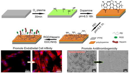
Chemical modification using dopamine, polyethylenimine, RGD and heparin enabled simultaneous promotion of endothelial cell affinity and antithrombogenicity of polytetrafluoroethylene.
1 Introduction
Prosthetic vascular grafts, namely polyethylene terephthalate (PET, Dacron) and expanded polytetrafluoroethylene (ePTFE), have been successfully utilized as large-diameter vessel replacements owing to their high mechanical strength, flexibility, biocompatibility, and commercial availability.1, 2 In addition, the massive blood flow in large-diameter blood vessels aids in the prevention of blood clots. However, the long-term patency of prosthetic vascular grafts is discouraging in small diameter vascular grafts (SDVGs) (< 6 mm) due to the high risk of luminal thrombosis that is caused by a lack of endothelial cells and anastomotic intimal hyperplasia.2, 3 The primary physiological function of endothelial cells is to facilitate blood flow by providing a suitable hemocompatible and antithrombogenic surface.4 To mimic the native physiological structure and properties of blood vessels, vascular tissue engineering strategies have been proposed and have become an important topic in biomedical engineering.
So far, various biodegradable synthetic materials, such as poly (lactic acid) (PLA), poly (lactic-co-glycolic acid) (PLGA), poly (ε-caprolactone) (PCL), and polyurethane (PU), have been employed to fabricate SDVGs.5–8 Although these materials have been found to be biocompatible with endothelial cells, they suffer from a slow endothelialization rate and a high risk of thrombosis. How to improve the endothelial cell affinity and antithrombogenicity of synthetic SDVGs are critical challenges for vascular tissue engineering. The major reason for inferior endothelial cell affinity is the lack of bioactive binding sites on these hydrophobic materials. Therefore, surface modification is highly desired for promoting the bioactivity of synthetic materials since surface modification has the unique advantage of altering the surface chemistry without interfering with the material’s bulk properties.9 Hydrophobic surfaces are typically difficult to modify, especially in an aqueous environment, due to the lack of hydrophilic functional groups. In the present study, we choose PTFE, which is the most hydrophobic and chemically inert material used in vascular grafts, with the aim of developing a general modification method to enhance the endothelial cell affinity and antithrombogenicity of synthetic biomaterials.
Plasma treatment is a practical physical modification approach for altering a material’s surface energy. Earlier studies have demonstrated the positive effect of plasma treatment on improving PTFE biocompatibility. For example, ammonia-plasma-treated PET and PTFE showed the enhanced adhesion and growth of endothelial cells and the slightly upregulated expression of adhesion molecules.10 Amide- and amine-plasma-treated PTFE showed an enhanced endothelial cell lining and stimulated the formation of an endothelial cell monolayer.11 However, the functional groups introduced via plasma treatment are limited and the introduced hydrophilic groups are not stable long-term.6
Dopamine (DA), a mussel adhesive protein-inspired molecule,12 has aroused extensive interest since it can virtually adhere to any solid surfaces, regardless of wettability, through irreversible covalent bonds formed in an alkaline aqueous solution.13–16 Moreover, it is an important organic chemical that is found in the human brain and body.17 Dopamine functions as a neurotransmitter in the brain and has a stimulating effect on nerve cells and the nervous system.18, 19 It has also shown positive effects on myocytes, fibroblasts, and osteoblasts when combined with synthetic biomaterials.20–22 Dopamine was previously self-polymerized on a PTFE surface, without the need for complex linkers, and was able to promote the proliferation of mouse osteoblasts.23 Thus, dopamine modification opens a new path for the functionalization of hydrophobic material surfaces.
Arginine–glycine–aspartic acid (RGD), a tri-amino acid sequence, is the most common peptide motif responsible for cell adhesion to the extracellular matrix (ECM).24 It has been extensively used to enhance cell attachment on biomaterials. Since RGD is readily dissolved in water, it has to be chemically grafted onto a substrate, while the grafting of RGD onto hydrophobic surfaces is fairly difficult. A practical solution is to combine a hydrophobic polymer with a hydrophilic material like alginate or collagen prior to RGD grafting.25, 26 However, doing so deteriorates the mechanical property advantages of synthetic polymers and increases fabrication cost. Therefore, we believe that dopamine modification will better facilitate the grafting of RGD on hydrophobic surfaces.
Although introducing an endothelial cell layer is the optimum solution for the prevention of thrombosis, the risk is still present if the surface is not fully covered by an endothelial cell layer. Therefore, improving the antithrombogenicity is highly desirable in addition to promoting a fast endothelialization rate. The incorporation of heparin is probably the most effect way to improve antithrombogenicity due to its excellent anticoagulation properties. Platelet adhesion was significantly reduced on various heparin-modified materials, such as chitosan/graphene oxide hydrogels, collagen-coated PTFEs, porous PLA membranes, and decellularized matrices.27–30 Heparin should be preferentially immobilized on the substrate surface since heparin molecules may gradually release into the blood flow and cause low sustainability in long-term implantation applications.31 For this reason, fast endothelialization is necessary to remedy the gradually decreasing heparin level.
On these bases, the aim of the present study is to provide a facile method for hydrophobic surface modification to promote endothelial cell affinity and antithrombogenicity simultaneously. PTFE was chosen due to its high hydrophobicity, its wide use as vascular grafts, and its availability. A series of modifications were performed on the PTFE to gradually enhance its biocompatibility, and the effect of each modification step was studied comprehensively. PTFE was first treated with O2 plasma, and then coated with dopamine. After that, a trace amount of polyethylenimine (PEI) was grafted in order to introduce amino groups onto the substrate’s surface since both RGD and heparin are carboxyl groups containing biomolecules that are difficult to conjugate with the phenolic hydroxyl/quinone groups of polymerized dopamine.9, 32 Finally, RGD or RGD/heparin were grafted onto the PTFE surface through (1-ethyl-3-(3-dimethylaminopropyl)-carbodiimide) (EDC)/N-hydroxysuccinimide (NHS) coupling chemistry. In this procedure, all chemical modifications were performed in an aqueous solution at room temperature, and are thus very suitable for scale-up. Most importantly, the RGD/heparin-modified PTFE showed excellent endothelial cell affinity and antithrombogenicity, which further demonstrated the feasibility of this procedure in the modification of SDVGs.
2 Experimental Methods
2.1 Materials
Medical-grade PTFE sheets with a thickness of 1 mm were purchased from Scientific Commodities Inc. All other chemicals were purchased from Sigma–Aldrich and used as received. DI water was used throughout the experiment.
2.2 PTFE Modification
Since the main focus of this study was on evaluating the effectiveness of various surface modification methods and their effect on cell behavior and platelet adhesion, all studies were performed on flat PTFE sheets to make sure all differences in results were solely caused by the surface chemistry of different modifications. PTFE sheets were first cleaned by ultrasonication in a 20% ethanol solution for 30 min. The PTFE sheets were then treated with oxygen plasma to enhance their surface hydrophilicity via a plasma etcher (PlasmaEtch PE-200) at an RF power of 200 W for 30 min at an oxygen flow rate of 20 cm3/min. It was found that 30 minutes of treatment resulted in a water contact angle of 90°, which should be hydrophilic enough to facilitate later modifications. The plasma-treated PTFE sheet was named P-PTFE. P-PTFE was further coated with dopamine (DA) by immersing it into a 2 mg/mL dopamine solution with a pH of 8.5 adjusted by 10 mM tris(hydroxymethyl)aminomethane for 16 h at room temperature. After coating, samples were rinsed with DI water 5 times and dried with nitrogen. Dopamine-coated P-PTFE sheets were named DA-PTFE. To further enhance the surface biocompatibility and anti-thrombogenic properties, RGD and heparin were chemically grafted onto DA-PTFE via a thin layer of PEI molecules. Briefly, PEI was dissolved in a citric acid/sodium phosphate dibasic buffer solution with a pH of 5.5 at a concentration of 0.5 mg/mL. DA-PTFE was immersed in the PEI solution for 1 h at room temperature, then rinsed with DI water and dried using nitrogen. Another buffer solution containing 20 mM of EDC, 50 mM of NHS, and 0.1 M MES was prepared. An RGD solution (100 μg/mL) and an RGD/heparin solution (100 μg/mL for RGD and 1 mg/mL for heparin) were prepared using the above buffer.33 PEI-modified samples were soaked separately in these solutions overnight, followed by sufficient washing and drying, to prepare RGD-grafted PTFE, which was named RGD-PTFE, and RGD/heparin-grafted PTFE, which was named R/H-PTFE.
2.3 General Characterization of Prepared PTFE Sheets
Fourier transform infrared (FTIR) spectra were recorded in transmittance mode to verify the modifications using a Bruker Tensor 27 spectrometer in the range of 4000–600 cm−1, with a resolution of 4 cm−1. X-ray photoelectron spectroscopy (XPS) measurements of different modified PTFE samples were performed on an X-ray photoelectron spectrometer with a focused, monochromatic K-alpha X-ray source and a monoatomic/cluster ion gun (Thermo Scientific). The C1s core-level signal spectra were Gaussian fitted and the proportion of each bond was determined from the peak area ratios. Scanning electron microscopy (SEM) was used to characterize the morphological properties. Samples were first coated with a thin layer of gold and then imaged using a fully digital LEO GEMINI 1530 SEM (Zeiss, Germany) at a voltage of 3 kV. The surface topography of different modified PTFE samples was analyzed using a Bruker BioScope Catalyst atomic force microscope (AFM) in tapping mold. The wettability of the modified PTFE samples was measured by a video contact angle instrument (Dataphysics, OCA 15) using 7 μL of DI water droplets with the sessile drop method.
2.4 Platelet Adhesion Test
Platelet adhesion tests were performed to investigate the antithrombogenicity of the modified PTFE sheets. Platelet-rich-plasma (PRP) was extracted from fresh human blood stabilized with 3.8% sodium citrate as an anti-coagulant (Innovative Research). The blood was centrifuged at 1500 rpm for 15 min to obtain PRP34. For the platelet adhesion test, samples were first incubated in phosphate-buffered saline (PBS) at 37 °C for 1 h. Then, PBS was aspirated and 500 μL of PRP were added, followed by incubation at 37 °C for 2 h. After incubation, samples were rinsed three times with PBS and treated with 2.5 wt% glutaraldehyde in PBS at 4 °C for 1 day. After that, samples were subjected to a series of ethanol solution washes (50%, 70%, 80%, 90%, and 100%) and dried in a desiccator overnight, followed by gold coating and imaging using SEM.
2.5 Human Umbilical Vein Endothelial Cell (HUVEC) Culture
Human umbilical vein endothelial cells (HUVECs; Lonza) were maintained on T75 tissue culture-treated polystyrene flasks. Cells were fed every other day with an endothelial cell growth medium EGM-2-MV bullet kit (Lonza). Prepared PTFE sheets were cut to the same size, put in 24-well tissue culture plates (TCPs), and washed in a 20% ethanol solution 5 times, followed by washing 3 times with PBS. They were then sterilized with ultraviolet (UV) light for 30 min. HUVECs were detached enzymatically with a trypsin–EDTA solution and seeded on the samples at a density of 1×10⁴ cells/cm2 for the live/dead assay and MTS assay. They were seeded at a density of 1×10³ cells/cm2 for the cytoskeleton assay. Spent medium was aspirated and replaced with 1 mL of fresh medium daily for screening samples. HUVECs were also cultured on TCPs as a control.
2.6 Biological Characterization
Initial cell attachment was evaluated at 4 h after cell seeding. The cells were fixed in 4% paraformaldehyde for 15 min, followed by a PBS rinse, and then treated with 0.1% Triton-X in PBS for 5 min at room temperature. They were rinsed again with PBS and stained with 3 μM 4′, 6-diamidino-2-phenylindole (DAPI) for 1 hour at room temperature. Samples were then rinsed with PBS and imaged using a Nikon Eclipse Ti-E inverted fluorescence microscope.
Cell viability was determined after culturing for 7 days and 14 days. Viability was assessed via a live/dead viability/cytotoxicity kit (Life Technologies). Green fluorescent calcein-AM was used to target the esterase activity within the cytoplasm of living cells, while the red fluorescence ethidium homodimer-1(EthD-1) was used to indicate cell death. Stained cells were imaged with a Nikon A1RSi inverted confocal microscope system. The number of collected cells that fluoresced red and green were counted with an Accuri C6 (BD Biosciences) flow cytometer to obtain viability data. Briefly, the stained cells of the live/dead assay were detached from the scaffolds by incubation in 250 μL of trypsin (Life Technologies) per well at 37 °C for 5 min. Then the cells were collected and centrifuged at 1000 rpm for 5 min. Next, the supernatant was aspirated and the cells were resuspended in 600 μL of PBS and filtered prior to analysis.
Cell proliferation was assessed at day 7 and day 14 by MTS assay using the CellTiter 96 Aqueous One Solution kit (Promega Life Sciences). Cells were first treated with media containing a 20% MTS solution and allowed to incubate for 1 h. After incubation, 100 μL of spent media were transferred into a clear 96-well plate. The absorbance of the plates at the 450 nm wavelength was read with a Glomax-Multi+Multiplate Reader (Promega). The subsequent number of cells was determined relative to the negative control.
The shape and cytoskeleton organization of the cells were determined by phalloidin–tetramethylrhodamine B isothiocyanate (phalloidin–TMRho, Sigma) staining. For this assay, cells were first fixed following the same procedure in the cell attachment assay. They were then treated with 0.3 μM of phalloidin–TMRho with DAPI for 1 hour at room temperature. Next, samples were washed with PBS and imaged using the same confocal microscope.
The interaction between cells and substrate was observed using SEM. Briefly, the samples stained with phalloidin/DAPI were dehydrated through a series of ethanol solution (50%, 70%, 80%, 90%, 100%) washes and sufficiently dried in a desiccator. They were then coated with gold and imaged using SEM.
2.7 Statistical Analysis
All biological results are presented as mean ± standard deviation. All of the values were averaged at least in triplicate. The data were analyzed using the one-way analysis of variance method (ANOVA). The Turkey’s test was then used to evaluate the specific differences of the data, and these differences were considered statistically significant at p < 0.05.
3 Results and Discussion
3.1 Surface Chemistry
A series of surface modifications were carried out on flat PTFE sheets in this study as shown in Schematic 1. We investigated the effect of each modification on the cellular substrate interaction to find a pragmatic way to enhance the bioactivity of the hydrophobic surfaces. Oxygen plasma was first used to introduce hydrophilic groups on the PTFE surface prior to dopamine (DA) coating. Although it has been reported that dopamine is able to coat any surface, regardless of hydrophobicity,13, 15 we found that the coating efficiency was greatly improved when the PTFE was first treated with O2 plasma. As evidenced in Figure S1, the plasma-treated PTFE showed a distinctly darker color than the PTFE without plasma treatment, thus indicating that more dopamine was coated on the P-PTFE. In order to further graft bioactive molecules onto the substrate surface, a very thin layer of polyethylenimine (PEI) was immobilized on the polydopamine to introduce reactive amino groups on the substrate surface.35 The PEI concentration was controlled at a low level (0.5 mg/mL) since we previously found that the addition of a trace amount of PEI was helpful to improve cell adhesion, while an excess amount of PEI caused cell death.36 Chemical grafting of RGD or RGD/heparin was performed using EDC/NHS grafting chemistry. In this grafting process, carboxyl groups on RGD and heparin were reacted while the bioactive component of RGD and the antithrombosis sulfo group of heparin were preserved and exposed on the substrate surface.
Schematic 1.
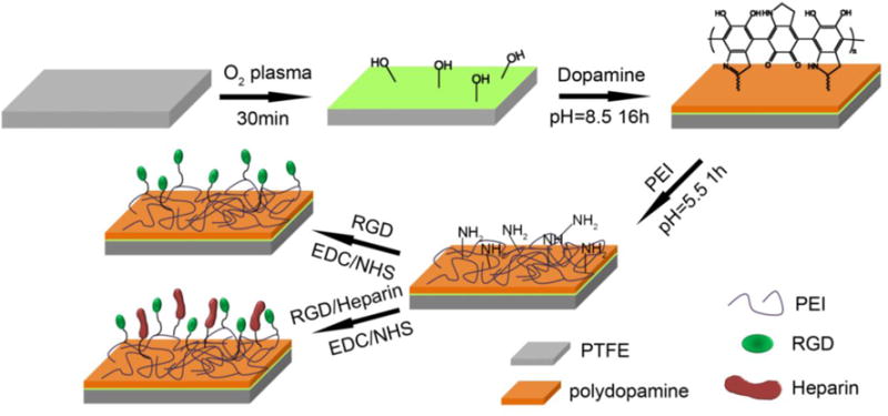
Stepwise surface modification procedure of PTFE. PTFE was first treated with O2 plasma to obtain P-PTFE, dopamine (DA) was polymerized on P-PTFE to obtain DA-PTFE, then PEI was immobilized on DA-PTFE, followed by the grafting of RGD or RGD/heparin to obtain RGD-PTFE or R/H-PTFE, respectively.
The chemical composition of the modified PTFE sheets was first characterized using FTIR. As shown in Figure 1, all materials showed very similar peak patterns due to the strong signal from the PTFE substrate. However, the difference among samples can be seen when specific regions are enlarged. The plasma-treated PTFE (P-PTFE) showed the same peak pattern as PTFE, except for a small wide peak at 3300 cm−1 indicating the introduction of a small amount of hydroxyl groups. The intensity of this peak significantly increased after dopamine coating due to the O–H and N–H bonds of polydopamine.37 Moreover, another peak attributed to C=O presented at 1615 cm−1, and the peak for C=N and C=C was also observed at 1512 cm−1.38, 39 These results indicate the successful coating of dopamine on the substrate surface. The RGD-grafted PTFE showed more intense peaks in the enlarged regions. The increase of the peak at 3300 cm−1 was attributed to the N–H from PEI and RGD. The peaks at 1702 cm−1 and 1464 cm−1 corresponded to the amide I and III of RGD. Interestingly, the wavenumbers of these peaks shifted higher compared to the freeze-dried RGD from the references.40, 41 This might have been due to the formation of hydrogen bonds with dopamine, which would further immobilize the RGD on the substrate surface. When heparin was further grafted onto the PTFE surface, a shoulder peak assigned to S=O asymmetry vibration presented on the FTIR spectrum at 1018 cm−1.42 Additionally, the intensity of the C=O peak at 1615 cm−1, and the peak at 3300 cm−1, increased, thus indicating the successful grafting of heparin. The peak at 2928 cm−1 corresponded to the symmetric stretching of CH2, and the peaks at 2850 and 2940 cm−1 were assigned to the antisymmetric stretching of CH2. The increase in the intensity of these peaks reflected the increase of coating materials on the material surfaces after modification.
Figure 1.
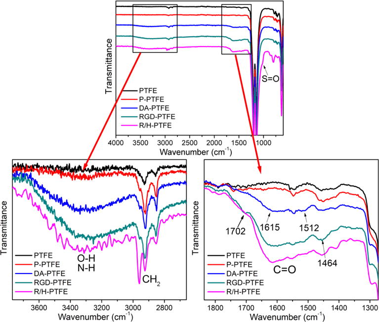
FTIR spectra of PTFE, P-PTFE, DA-PTFE, RGD-PTFE, and R/H-PTFE. Two regions are enlarged for better comparison.
Since the strong signal from PTFE in the FTIR measurements may hide some details in the surface chemistry, XPS was used to further characterize the surface layer of the modified samples. From the survey scans (Figure S2) and atom percentage statistical data (Table S1), it was found that only C and F were detected on PTFE, while 4.1% O was detected on P-PTFE, thus indicating the introduction of hydrophilic groups. Nitrogen was detected on the surface of DA-PTFE and RGD-PTFE at a rate of 5.5% and 8.2%, respectively, suggesting the introduction of bioactive components. On the R/H-PTFE, 2.1% of S was detected, which confirmed the grafting of heparin. The C1s core level scans (Figure 2) show the detailed information of carbon-containing bonds on the material surface. According to statistical data (Table S2), the proportion of CF2 and CF3 was reduced by more than half after plasma treatment, and it was less than 5% after dopamine coating, thus suggesting an increase in surface energy. As expected, C–O, C=O, and C–N bonds were present on DA-PTFE, and the proportion of C–N bonds greatly increased after RGD grafting, which was attributed to the massive amide bonds on RGD. Similarly, C–O bonds dominated when heparin was grafted, which corresponded to the increase in C–O–C linkages from heparin.13 Moreover, the O1s scan results indicated that the oxygen containing groups on the P-PTFE and DA-PTFE surfaces were mostly C–O–H, while the proportion of C–O–C and C=O was higher on the RGD-PTFE and R/H-PTFE surfaces (Figure S3). Therefore, the XPS results further confirmed the success of each modification step. The surface chemistry of PTFE was tuned by dopamine coating and RGD or RGD/heparin grafting.
Figure 2.
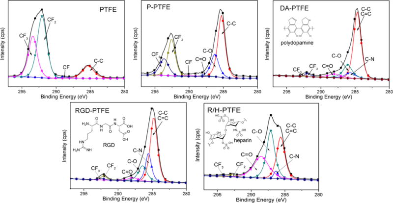
Gauss-fitted C1s high-resolution scans of PTFE, P-PTFE, DA-PTFE, RGD-PTFE, and R/H-PTFE showing the composition of different carbon bonds. Statistical data is listed in Table S2 in the Supporting Information. The insets show the chemical structure of polydopamine, RGD, and heparin.
3.2 Surface Morphology
The surface morphology of modified PTFE sheets was imaged using SEM. As can be seen from Figure 3, neat PTFE showed a relatively smooth surface. After 30 min of O2 plasma treatment, some cracks showed on the P-PTFE surface indicating the cleavage of carbon bonds. Dopamine-coated PTFE (DA-PTFE) showed an obvious coating layer with increased surface roughness. It has been reported that self-polymerized polydopamine forms nanoparticles in an aqueous solution.43 When coated on PTFE, these particles merged to form a film, but some particulate morphology was still observable on the material surface. When RGD was grafted on DA-PTFE with the PEI layer, the surface morphology of RGD-PTFE remained about the same. Remarkably, when heparin was grafted on the surface, R/H-PTFE showed a much rougher surface with many nanoparticles (~50 nm) anchored to the substrate surface. This was because heparin molecules tend to aggregate and form nanoparticles when dried from an aqueous solution.44 A similar rough surface was also found when heparin was directly coated onto a poly(lactic acid) (PLA) membrane.28
Figure 3.
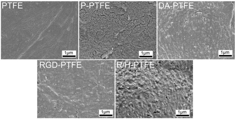
SEM images of the surface morphologies of PTFE, P-PTFE, DA-PTFE, RGD-PTFE, and R/H-PTFE samples.
The surface topography of modified PTFE sheets was further characterized using AFM to better quantify the change of surface roughness in each modification step. As shown in the 3D AFM images (Figure 4) and cross-sectional images (Figure S4), PTFE showed a height difference of 28 nm. The micro grooves seen on the images were caused by the finishing of the pristine PTFE sheets during production. After O2 plasma treatment, the height difference increased to 78 nm, thus indicating that some PTFE had been etched away. Gao et al. reported a greater increase in height difference (from 18 nm to 135 nm) when PTFE sheets were treated with N2 plasma for 3 h.1 The height difference further increased after dopamine coating and RGD grafting as shown in Figure 4. Notably, after grafting with RGD and heparin, the height difference increased to 209 nm, which was significantly higher than other samples. This was because of the nanoparticles formed by heparin and is in agreement with SEM observations. The increased surface roughness should be favorable for cell attachment since rough surfaces have been found to facilitate serum protein adsorption and enhance osteoblast cell adhesion.45
Figure 4.
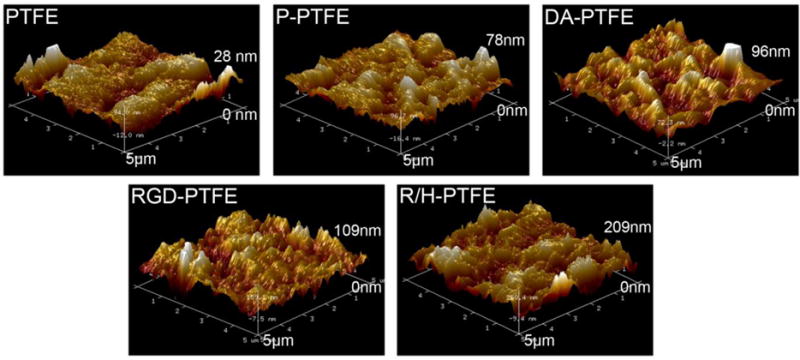
Three-dimensional AFM images of PTFE, P-PTFE, DA-PTFE, RGD-PTFE, and R/H-PTFE across a 5 μm × 5 μm area. The height differences are marked on the images. The corresponding cross-sectional images and height profiles are provided in Figure S4 of the supporting information.
3.3 Surface Wettability and Platelet Adhesion
A great challenge for vascular grafts is the risk of thrombosis due to the coagulation of platelets. Platelet adhesion was evaluated to understand the effect of surface modification on the risk of thrombosis. As shown in Figure 5a, the platelets adhered on the substrate had round shapes indicating that they generally had a low attachment force to the substrate. The number of attached platelets on P-PTFE, DA-PTFE, and RGD-PTFE was significantly higher than on PTFE and R/H-PTFE as shown in the statistical results (Figure 5b). Remarkably, almost no platelets adhered to R/H-PTFE. We believe that the lower platelet adhesion for PTFE was associated with its low surface roughness and high hydrophobicity. As found in the water contact angle (WCA) measurements (Figure 5c), the WCA decreased after each modification step because more hydrophilic components were introduced in each step. The surface roughness, on the contrary, gradually increased as demonstrated above. The combination of these two factors caused increased platelet adhesion after modification. However, although R/H-PTFE possessed the lowest WCA and the highest surface roughness, it showed very low platelet adhesion. This was mainly attributed to the introduction of heparin, which is a very effective anticoagulant due to its high negative charge density.31, 46
Figure 5.
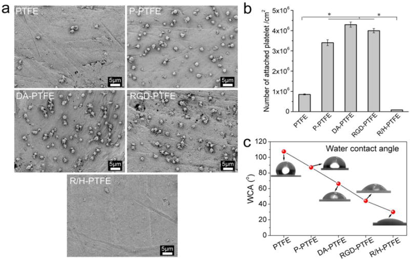
(a) SEM images of platelets attached to PTFE, P-PTFE, DA-PTFE, RGD-PTFE, and R/H-PTFE. (b) Statistical results of the platelet adhesion test. (c) Water contact angle results of different PTFE samples.
3.4 HUVEC Viability and Proliferation
Due to the high hydrophobicity of PTFE and low cell adhesion, PTFE vascular grafts could not be endothelialized, which resulted in a poor patency rate and a high risk of thrombosis when the diameter of grafts was less than 6 mm.47, 48 Although the grafting of heparin prevented platelet adhesion, endothelialization of vascular grafts is preferred to prevent luminal thrombosis and intimal hyperplasia, thereby improving the long-term patency of PTFE grafts.49, 50 In order to investigate the effect of different modifications on cellular–substrate interactions, HUVECs were cultured on pristine PTFE and different PTFE samples.
Initial cell attachment was evaluated 4 h after cell seeding. It was found that the cell attachment on PTFE and P-PTFE samples was significantly lower than on other samples. The dopamine-coated substrate showed improved cell adhesion that was mainly attributed to native serum proteins—which could interact with the adhesion receptors on the cell membrane—being absorbed on the dopamine surface.12, 23 The samples grafted with RGD and RGD/heparin had significantly higher cell seeding than the one coated only with dopamine (Figure S5). This was because, when RGD was grafted, the surface energy of the substrate increased further. This should facilitate protein adhesion, and, more importantly, RGD itself can interact with the receptors on the cell membrane to enhance cell adhesion, thus resulting in further enhanced cell adhesion.51, 52 It was found that the difference of cell attachment on RGD-PTFE and R/H-PTFE was not statistically significant, indicating that the addition of heparin did not further improve cell attachment. Thus, RGD may have played the major role in facilitating cell attachment. This result is consistent with published works since heparin is usually used together with adhesion peptides to facilitate cell attachment.53, 54
The viability of HUVECs on different modified PTFE substrates was investigated using a live/dead assay. The assay uses calcein-AM to stain live cells with green fluorescence and EthD-1 to target dead cells with red fluorescence. The day 7 results are shown in Figure 6a and the day 14 results are shown in Figure S6. The fluorescence images showed that HUVECs were able to grow on all substrates, while the number of cells and the percentage of live cells differed among them. The statistical results of the cell viability from flow cytometry are shown in Figure 6a, and the cell population from the MTS assay is shown in Figure 6b. The results suggest that neat PTFE had a very low cell population and cell viability at both day 7 and day 14 time points, indicating that cells were not able to proliferate or proliferated slowly on PTFE. Moreover, the cell viability on PTFE was the lowest. After O2 plasma treatment, P-PTFE showed improved cell proliferation and viability at both time points. A significant improvement was achieved when PTFE was coated with dopamine. Compared to PTFE, DA-PTFE showed 4.5 times the cell population of PTFE at day 7, and it further increased to 8.4 times as many on day 14. When RGD or RGD/heparin was grafted, the cell proliferation improved further. Remarkably, at day 14, the number of cells on RGD-PTFE was 11 times that of PTFE, and it was also significantly higher than DA-PTFE and TCP. However, the difference between RGD-PTFE and R/H-PTFE was not significant, suggesting that RGD was the main cause of the increased cell affinity. This trend was maintained at both day 7 and day 14 time points and was consistent with the cell attachment results, which indicated that dopamine and RGD were able to not only facilitate initial cell attachment, but also stimulate cell growth over time. In addition, it was observed that HUVECs cultured on RGD-PTFE and R/H-PTFE showed smaller sizes than cells cultured on other samples (Figure 6a). This was because of the significant increase in the cell population over the limited sample area. At day 14, the HUVECs cultured on DA-PTFE and TCP also became smaller compared to day 7 (Figure S6).
Figure 6.
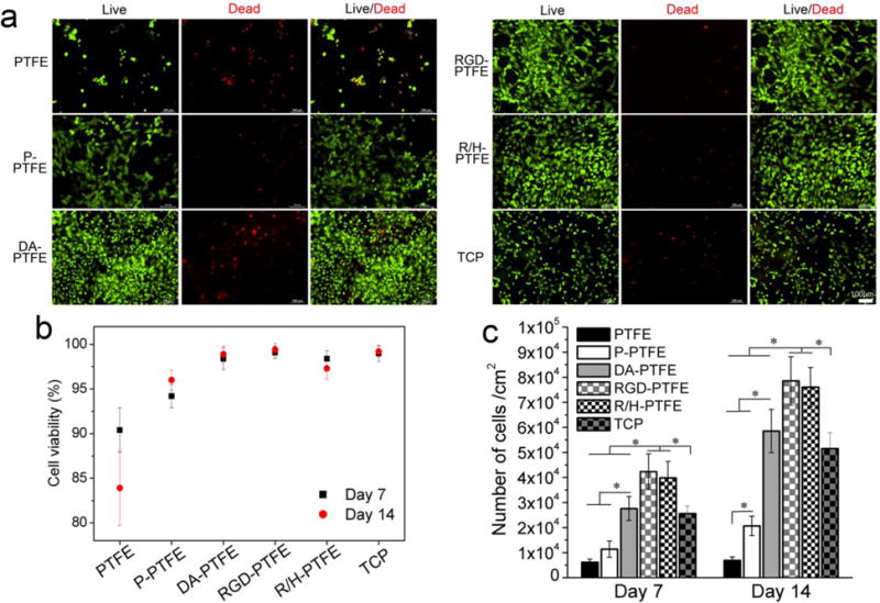
(a) Fluorescence images of HUVECs cultured on different PTFE substrates for 7 days. Live cells were stained with calcein-AM (green) and dead cells were stained with EthD-1 (red). (b) Statistical results of cell viability from live/dead assay, and (c) statistical results of cell proliferation from MTS assay at day 7 and day 14 time points.
3.5 HUVEC Cytoskeleton and Morphology
In order to investigate the cell phenotype, HUVECs were seeded on different PTFE substrates at a low density (1×10³ cells/cm2) and cultured for 14 days. The cytoskeletons of the cells were stained red with phalloidin–TMRho, and cell nuclei were stained blue with DAPI. Figure 7a shows the cytoskeleton of HUVECs cultured on different PTFE substrates for 7 days. As can be seen, both cell size and nuclei size of HUVECs cultured on PTFE were smaller than cells on other samples. The cells were not spread out and the fluorescence intensity was weak, thus indicating that cells did not show a healthy growing state. After a series of modifications, the cellular–substrate interaction greatly improved. For statistical comparison, the average projected cell area and aspect ratio of the cells were measured as shown in Figures 7b and c. It was found that samples with DA, RGD, and RGD/heparin modification showed significantly larger cell sizes than cells on PTFE and P-PTFE, and the cells were more spread out and stretched on those samples. Notably, the cells on RGD-PTFE and R/H-PTFE showed extremely flourishing growing states with a typical spindle-like cell morphology and filopodia. The average aspect ratio of the cells on RGD-PTFE and R/H-PTFE was over 3, which was significantly larger than those grown on PTFE and TCP (Figure 7c). Moreover, the filaments in the cells can be clearly seen on cells grown on RGD-PTFE and R/H-PTE, thus indicating highly extended cell morphology. This was mainly attributed to the RGD, which was able to stimulate cell attachment and spreading by interacting with proteins on the cell membrane.55 After 14 days of cell culture, the number of cells greatly increased on the DA-PTFE, RGD-PTFE, and R/H-PTFE samples (Figure S7). In some regions of the RGD-PTFE and R/H-PTFE samples, cells started to grow on top of each other to form dense cell aggregates. Similar to the live/dead assay, the cell size decreased at day 14 due to the great increase in the number of cells, thus the projected cell area was not measured at day 14. All of these results strongly suggest that dopamine coating and RGD and heparin grafting greatly improved the biocompatibility and endothelial cell affinity of PTFE.
Figure 7.
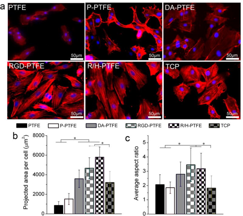
(a) Fluorescence images showing the cytoskeleton of HUVECs cultured on different PTFE substrates for 7 days, and the measurement results of (b) the average projected area per cell, and (c) the average aspect ratio per cell.
In order to reveal the cellular–substrate interactions in detail, the samples at day 7 were imaged using SEM to observe the morphology of the cells on different substrates. As shown in Figure 8, cells were rarely present on PTFE samples. Although more cells can be seen on P-PTFE compared with PTFE, many of the cells were round and a gap can clearly be seen between the cells and the substrate, indicating poor cell adhesion. On the DA-PTFE sample, cells were flattened and showed tight adhesion to the substrate. Many cells were connected with each other by extended filopodia. Meanwhile, the cell boundaries were clearly seen and some cells observed were not fully spread. Remarkably, individual cells and cell boundaries were not observed at low magnification on the RGD-PTFE and R/H-PTFE samples. When zoomed in to high magnification, it can be seen that the cell membranes were greatly flattened and extended. For better observation, the cell membranes were highlighted in red on the enlarged SEM images. As one can see, the lamellipodia and filopodia were tightly attached to the substrate, and the boundary of the cell membrane was difficult to see, thus suggesting strong cellular–substrate interactions.
Figure 8.
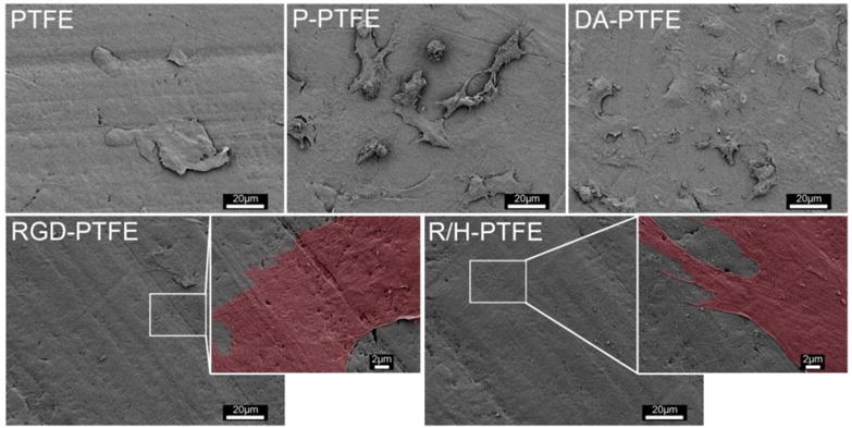
SEM images of HUVECs cultured on different PTFE substrates for 7 days showing the interaction between cells and substrate.
4. Conclusions
In summary, a facile modification method has been developed in this study for the functionalization of PTFE with bioactive molecules including dopamine (DA), RGD, and heparin towards their application as vascular grafts. Oxygen plasma treatment activated hydrophilic groups on PTFE’s surface and facilitated dopamine coating. RGD and heparin were immobilized on DA-PTFE through a thin PEI layer. Successful modification in each step was verified via FTIR and XPS. The surface roughness increased as more components were grafted onto the PTFE surface, and the hydrophilicity increased due to the increased number of hydrophilic groups. Platelet adhesion increased after dopamine and RGD modification, but it decreased dramatically when heparin was grafted onto the surface, thereby demonstrating excellent antithrombogenicity. In vitro HUVEC cultures revealed that all of the modifications had a positive effect on the biocompatibility of PTFE. The initial cell attachment, cell viability, and cell proliferation all improved significantly when dopamine and RGD were grafted onto the PTFE surface, and the incorporation of RGD outperformed dopamine coating alone. Endothelial cells cultured on RGD- and RGD/heparin-grafted PTFE substrates exhibited favorable cell morphologies and strong cell–substrate interactions owing to the significantly enhanced cell affinity. Therefore, we achieved simultaneous improvement of endothelial cell affinity and antithrombogenicity of hydrophobic surfaces through this pragmatic modification method, which is highly suitable for the modification of SDVGs to stimulate fast endothelialization and effective antithrombosis.
Supplementary Material
Acknowledgments
Research reported in this article was partially supported by the NHLBI of the National Institutes of Health under award number U01HL134655, the Office of the Vice Chancellor for Research and Graduate Education, and the Wisconsin Institute for Discovery at the University of Wisconsin–Madison. The content is solely the responsibility of the authors and does not represent the official views of the National Institutes of Health. The first two authors would also like to acknowledge the support of the National Natural Science Foundation of China [51603075, 21604026] and the Fundamental Research Funds for the Central Universities of China [2015ZM093].
Notes and References
- 1.Gao A, Hang RQ, Li W, Zhang W, Li PH, Wang GM, Bai L, Yu XF, Wang HY, Tong LP, Chu PK. Biomaterials. 2017;140:201–211. doi: 10.1016/j.biomaterials.2017.06.023. [DOI] [PubMed] [Google Scholar]
- 2.Chlupac J, Filova E, Bacakova L. Physiol Res. 2009;58:S119–S139. doi: 10.33549/physiolres.931918. [DOI] [PubMed] [Google Scholar]
- 3.Deutsch M, Meinhart J, Zilla P, Howanietz N, Gorlitzer M, Froeschl A, Stuempflen A, Bezuidenhout D, Grabenwoeger M. J Vasc Surg. 2009;49:352–362. doi: 10.1016/j.jvs.2008.08.101. [DOI] [PubMed] [Google Scholar]
- 4.Seib FP, Herklotz M, Burke KA, Maitz MF, Werner C, Kaplan DL. Biomaterials. 2014;35:83–91. doi: 10.1016/j.biomaterials.2013.09.053. [DOI] [PMC free article] [PubMed] [Google Scholar]
- 5.Mi HY, Jing X, Yu E, McNulty J, Peng XF, Turng LS. Mater Lett. 2015;161:305–308. [Google Scholar]
- 6.Jing X, Mi HY, Salick MR, Cordie TM, Peng XF, Turng LS. Mat Sci Eng C-Mater. 2015;49:40–50. doi: 10.1016/j.msec.2014.12.060. [DOI] [PubMed] [Google Scholar]
- 7.Rocco KA, Maxfield MW, Best CA, Dean EW, Breuer CK. Tissue Eng Part B-Re. 2014;20:628–640. doi: 10.1089/ten.TEB.2014.0123. [DOI] [PubMed] [Google Scholar]
- 8.Landau S, Szklanny AA, Yeo GC, Shandalov Y, Kosobrodova E, Weiss AS, Levenberg S. Biomaterials. 2017;122:72–82. doi: 10.1016/j.biomaterials.2017.01.015. [DOI] [PubMed] [Google Scholar]
- 9.Yang Y, Qi PK, Ding YH, Maitz MF, Yang ZL, Tu QF, Xiong KQ, Leng Y, Huang N. J Mater Chem B. 2015;3:72–81. doi: 10.1039/c4tb01236d. [DOI] [PubMed] [Google Scholar]
- 10.Pu FR, Williams RL, Markkula TK, Hunt JA. Biomaterials. 2002;23:2411–2428. doi: 10.1016/s0142-9612(01)00377-5. [DOI] [PubMed] [Google Scholar]
- 11.Tseng DY, Edelman ER. Journal of biomedical materials research. 1998;42:188–198. doi: 10.1002/(sici)1097-4636(199811)42:2<188::aid-jbm4>3.0.co;2-l. [DOI] [PubMed] [Google Scholar]
- 12.Lee H, Rho J, Messersmith PB. Adv Mater. 2009;21:431–+. doi: 10.1002/adma.200801222. [DOI] [PMC free article] [PubMed] [Google Scholar]
- 13.Ma L, Qin H, Cheng C, Xia Y, He C, Nie CX, Wang LR, Zhao CS. J Mater Chem B. 2014;2:363–375. doi: 10.1039/c3tb21388a. [DOI] [PubMed] [Google Scholar]
- 14.Lee H, Dellatore SM, Miller WM, Messersmith PB. Science. 2007;318:426–430. doi: 10.1126/science.1147241. [DOI] [PMC free article] [PubMed] [Google Scholar]
- 15.Schlaich C, Carnacho LC, Yu LX, Achazi K, Wei Q, Haag R. ACS Appl Mater Interfaces. 2016;8:29117–29127. doi: 10.1021/acsami.6b08487. [DOI] [PubMed] [Google Scholar]
- 16.Mi HY, Jing X, Huang HX, Turng LS. ACS Appl Mater Interfaces. 2017;9:37529–37535. doi: 10.1021/acsami.7b10901. [DOI] [PubMed] [Google Scholar]
- 17.Zucca FA, Segura-Aguilar J, Ferrari E, Munoz P, Paris I, Sulzer D, Sarna T, Casella L, Zecca L. Prog Neurobiol. 2017;155:96–119. doi: 10.1016/j.pneurobio.2015.09.012. [DOI] [PMC free article] [PubMed] [Google Scholar]
- 18.Wu J, Xie LL, Lin WZY, Chen QS. Drug Discov Today. 2017;22:1375–1384. doi: 10.1016/j.drudis.2017.03.007. [DOI] [PubMed] [Google Scholar]
- 19.Korshunov KS, Blakemore LJ, Trombley PQ. Front Cell Neurosci. 2017;11:91. doi: 10.3389/fncel.2017.00091. [DOI] [PMC free article] [PubMed] [Google Scholar]
- 20.Wang LY, Jiang JZ, Hua WX, Darabi A, Song XP, Song C, Zhong W, Xing MMQ, Qiu XZ. Adv Funct Mater. 2016;26:4293–4305. [Google Scholar]
- 21.Lee SJ, Lee D, Yoon TR, Kim HK, Jo HH, Park JS, Lee JH, Kim WD, Kwon IK, Park SA. Acta Biomater. 2016;40:182–191. doi: 10.1016/j.actbio.2016.02.006. [DOI] [PubMed] [Google Scholar]
- 22.Jing X, Mi HY, Napiwocki BN, Peng XF, Turng LS. Carbon. 2017;125:557–570. [Google Scholar]
- 23.Ku SH, Ryu J, Hong SK, Lee H, Park CB. Biomaterials. 2010;31:2535–2541. doi: 10.1016/j.biomaterials.2009.12.020. [DOI] [PubMed] [Google Scholar]
- 24.Kim S, Cui ZK, Fan JB, Fartash A, Aghaloo TL, Lee M. J Mater Chem B. 2016;4:5289–5298. doi: 10.1039/C6TB01154C. [DOI] [PMC free article] [PubMed] [Google Scholar]
- 25.Jeon HJ, Lee H, Kim GH. J Mater Chem B. 2015;3:3279–3287. doi: 10.1039/c5tb00057b. [DOI] [PubMed] [Google Scholar]
- 26.Lee JY, Chung J, Chung WJ, Kim G. J Mater Chem B. 2016;4:656–665. doi: 10.1039/c5tb01748c. [DOI] [PubMed] [Google Scholar]
- 27.Wei HL, Han LL, Tang YC, Ren J, Zhao ZB, Jia LY. J Mater Chem B. 2015;3:1646–1654. doi: 10.1039/c4tb01673d. [DOI] [PubMed] [Google Scholar]
- 28.Gao AL, Liu F, Xue LX. J Membrane Sci. 2014;452:390–399. [Google Scholar]
- 29.Chandy T, Das GS, Wilson RF, Rao GHR. Biomaterials. 2000;21:699–712. doi: 10.1016/s0142-9612(99)00231-8. [DOI] [PubMed] [Google Scholar]
- 30.Gong WH, Lei D, Li S, Huang P, Qi Q, Sun YJ, Zhang YJ, Wang Z, You ZW, Ye XF, Zhao Q. Biomaterials. 2016;76:359–370. doi: 10.1016/j.biomaterials.2015.10.066. [DOI] [PubMed] [Google Scholar]
- 31.Yao Y, Wang JN, Cui Y, Xu R, Wang ZH, Zhang J, Wang K, Li YJ, Zhao Q, Kong DL. Acta Biomater. 2014;10:2739–2749. doi: 10.1016/j.actbio.2014.02.042. [DOI] [PubMed] [Google Scholar]
- 32.Ham HO, Liu ZQ, Lau KHA, Lee H, Messersmith PB. Angew Chem Int Edit. 2011;50:732–736. doi: 10.1002/anie.201005001. [DOI] [PMC free article] [PubMed] [Google Scholar]
- 33.Sawyer AA, Hennessy KM, Bellis SL. Biomaterials. 2005;26:1467–1475. doi: 10.1016/j.biomaterials.2004.05.008. [DOI] [PubMed] [Google Scholar]
- 34.Hoshi RA, Van Lith R, Jen MC, Allen JB, Lapidos KA, Ameer G. Biomaterials. 2013;34:30–41. doi: 10.1016/j.biomaterials.2012.09.046. [DOI] [PMC free article] [PubMed] [Google Scholar]
- 35.Liu MY, Ji JZ, Zhang XY, Zhang XQ, Yang B, Deng FJ, Li Z, Wang K, Yang Y, Wei Y. J Mater Chem B. 2015;3:3476–3482. doi: 10.1039/c4tb02067g. [DOI] [PubMed] [Google Scholar]
- 36.Jing X, Mi HY, Salick MR, Cordie T, McNulty J, Peng XF, Turng LS. J Mater Res. 2015;30:1808–1819. [Google Scholar]
- 37.Mrowczynski R, Coy LE, Scheibe B, Czechowski T, Augustyniak-Jablokow M, Jurga S, Tadyszak K. J Phys Chem B. 2015;119:10341–10347. doi: 10.1021/acs.jpcb.5b01524. [DOI] [PubMed] [Google Scholar]
- 38.Luo HY, Gu CW, Zheng WH, Dai F, Wang XL, Zheng Z. Rsc Adv. 2015;5:13470–13477. [Google Scholar]
- 39.Zhang M, Zhang XH, He XW, Chen LX, Zhang YK. Nanoscale. 2012;4:3141–3147. doi: 10.1039/c2nr30316g. [DOI] [PubMed] [Google Scholar]
- 40.Mavropoulos E, Hausen M, Costa AM, Alves G, Mello A, Ospina CA, Mir M, Granjeiro JM, Rossi AM. J Mater Sci-Mater M. 2013;24:1271–1283. doi: 10.1007/s10856-013-4851-3. [DOI] [PubMed] [Google Scholar]
- 41.Yin HQ, Mai DS, Gan F, Chen XJ. Rsc Adv. 2014;4:9078–9085. [Google Scholar]
- 42.Bogdan N, Rodriguez EM, Sanz-Rodriguez F, de la Cruz MCI, Juarranz A, Jaque D, Sole JG, Capobianco JA. Nanoscale. 2012;4:3647–3650. doi: 10.1039/c2nr30982c. [DOI] [PubMed] [Google Scholar]
- 43.Cheng YL, Chen YW, Wang K, Shie MY. J Mater Chem B. 2016;4:6307–6315. doi: 10.1039/c6tb01377e. [DOI] [PubMed] [Google Scholar]
- 44.Cheng C, Sun SD, Zhao CS. J Mater Chem B. 2014;2:7649–7672. doi: 10.1039/c4tb01390e. [DOI] [PubMed] [Google Scholar]
- 45.Deligianni DD, Katsala ND, Koutsoukos PG, Missirlis YF. Biomaterials. 2001;22:87–96. doi: 10.1016/s0142-9612(00)00174-5. [DOI] [PubMed] [Google Scholar]
- 46.Limtiaco JFK, Jones CJ, Larive CK. Anal Chem. 2009;81:10116–10123. doi: 10.1021/ac901812y. [DOI] [PubMed] [Google Scholar]
- 47.Kannan RY, Salacinski HJ, Butler PE, Hamilton G, Seifalian AM. J Biomed Mater Res B. 2005;74B:570–581. doi: 10.1002/jbm.b.30247. [DOI] [PubMed] [Google Scholar]
- 48.Klinkert P, Post PN, Breslau PJ, van Bocke JH. Eur J Vasc Endovasc. 2004;27:357–362. doi: 10.1016/j.ejvs.2003.12.027. [DOI] [PubMed] [Google Scholar]
- 49.Liu T, Liu SH, Zhang K, Chen JY, Huang N. J Biomed Mater Res A. 2014;102:3754–3772. doi: 10.1002/jbm.a.35025. [DOI] [PubMed] [Google Scholar]
- 50.Kipshidze N, Dangas G, Tsapenko M, Moses J, Leon MB, Kutryk M, Serruys P. J Am Coll Cardiol. 2004;44:733–739. doi: 10.1016/j.jacc.2004.04.048. [DOI] [PubMed] [Google Scholar]
- 51.Mu Y. Phys Rev E. 2011;84:031906. doi: 10.1103/PhysRevE.84.031906. [DOI] [PubMed] [Google Scholar]
- 52.Hoesli CA, Garnier A, Juneau PM, Chevallier P, Duchesne C, Laroche G. Biomaterials. 2014;35:879–890. doi: 10.1016/j.biomaterials.2013.09.076. [DOI] [PubMed] [Google Scholar]
- 53.Choi WS, Joung YK, Lee Y, Bae JW, Park HK, Park YH, Park JC, Park KD. ACS Appl Mater Interfaces. 2016;8:4336–4346. doi: 10.1021/acsami.5b12052. [DOI] [PubMed] [Google Scholar]
- 54.Chiang NY, Chang GW, Huang YS, Peng YM, Hsiao CC, Kuo ML, Lin HH. J Cell Sci. 2016;129:2156–2169. doi: 10.1242/jcs.174458. [DOI] [PubMed] [Google Scholar]
- 55.Hersel U, Dahmen C, Kessler H. Biomaterials. 2003;24:4385–4415. doi: 10.1016/s0142-9612(03)00343-0. [DOI] [PubMed] [Google Scholar]
Associated Data
This section collects any data citations, data availability statements, or supplementary materials included in this article.


