Abstract
Functional outcomes, such as joint flexion and gait, are important indicators of efficacy in musculoskeletal research. Current technologies that objectively assess these parameters, including visual tracking systems and force plates, are challenging to deploy in long-term translational and clinical studies. To that end, we developed a wearable device that measures both physical activity and joint flexion using a single integrated sensor and magnet system, and hypothesized that it could evaluate post-operative functional recovery in an unsupervised setting. To demonstrate the feasibility of measuring joint flexion, we first compared knee motion from the wearable device to that acquired from a motion capture system to confirm that knee flexion measurements during normal human gait, predicted via changes in magnetic field strength, closely correlated with data acquired by motion capture. Using this system, we then monitored a porcine cohort after bilateral stifle arthrotomy to investigate longitudinal changes in physical activity and joint flexion. We found that unsupervised activity declined immediately after surgery, with a return to pre-operative activity occurring over a period of 2 weeks. By providing objective, individualized data on locomotion and joint function, this magnet-based system will facilitate the in vivo assessment of novel therapeutics in orthopaedic research.
Keywords: Joint Function, Motion Sensor, Large Animal Model, Translational Research
Introduction
Restoring locomotor function, such as full range of joint motion during gait, is the primary goal of treating musculoskeletal injury and deformity. Large animal models are uniquely suited to investigate treatments of joint diseases that affect humans, such as osteoarthritis, knee meniscal tears, and osteochondritis dissecans, as their size allows for experimentation in a clinically relevant, orthotopic setting1–3. Despite the ready availability of tissue-level assays that characterize structure, biology, and mechanics, methods that quantify the effects of treatment on joint-level function are limited. This information is critical for improving the efficacy of tissue-engineered implants in dynamic load-bearing environments, an emerging concept known as regenerative rehabilitation4,5. Ultimately, implant success is defined by the ability to restore joint contact mechanics and pain-free range of motion (ROM)6. Nonetheless, recent meta-analyses of translational large animal studies in the cartilage and meniscus fields found that such joint kinematic parameters are rarely evaluated7,8.
Quantitative assessment of joint function is challenging for animal studies. While semi-quantitative scores — for example, numerical rating scales and visual analogue scales — are commonly used to subjectively evaluate limb function, intra-and interobserver reliability are only strong when detecting severe lameness9. Established technologies that objectively assess gait and joint function, such as visual tracking systems10,11, pressure walkways12,13, and force plates14,15, are accurate but are also impractical to deploy in large, long-term translational studies. On the other hand, wearable motion sensors composed of accelerometers and gyroscopes (i.e., inertial measurement unit, or IMU) have the potential to provide objective, individualized data on animal activity and locomotion16. Basic accelerometer-based monitors have previously been employed to assess activity and locomotion patterns in canines with osteoarthritis17 and muscular dystrophy18, respectively, but these systems were limited to characterizing whole-body movement. A more sensitive lameness detection system for horses, developed by Keegan et al., used three IMUs to measure vertical asymmetry at the trot, localizing lameness to a particular limb19. Other sensor-based gait measurement systems recently developed for horses and dogs employ four IMUs, one sensor on each limb, at the walk and trot20,21.
Despite these advances in motion sensing technology, the application of multiple sensor components in a supervised environment limits their utility in preclinical research. Ideally, locomotion and joint function would be assessed in an unsupervised setting so that animal behavior are not altered by human presence. To address these limitations, we developed a wearable, magnet-based device using a single sensor board that measures both overall animal activity and joint-level function. First, to establish that this technology can quantify dynamic joint flexion, we compared knee flexion captured in healthy humans using this single-sensor paradigm and motion capture techniques. Next, using this wearable motion-tracking system, we recorded the recovery of porcine subjects after bilateral stifle arthrotomy, and hypothesized that the device would provide quantitative parameters regarding activity levels and joint flexion in the operated limbs.
Materials and Methods
Device Hardware:
Animal and human motion were measured using a wireless device that was developed with off-the-shelf components. The device consisted of a plastic enclosure containing a motion sensor (Sparkfun 9DoF Sensor Stick; SparkFun Electronics, Niwot, CO), microcontroller board (Arduino Fio v3; Sparkfun Electronics), radio board (XBee 1mW Trace Antenna; Digi International, Inc., Minnetonka, MN), data logger (Sparkfun OpenLog; Sparkfun Electronics), and 3.7 V polymer lithium ion battery (850 mAh, 53 mA operating current, 16 hours battery life; Sparkfun Electronics) (Fig. 1B). The sensor board integrated a triple-axis accelerometer, triple-axis gyroscope, and triple-axis magnetometer, and was calibrated prior to use via a custom software tool. A computer with a radio peripheral received transmitted sensor data to plot it in real time and to store to a text file for post-processing. Data were also locally stored on a microSD card (8 GB capacity).
Fig. 1. System for real-time remote monitoring of activity and measurement of joint flexion.
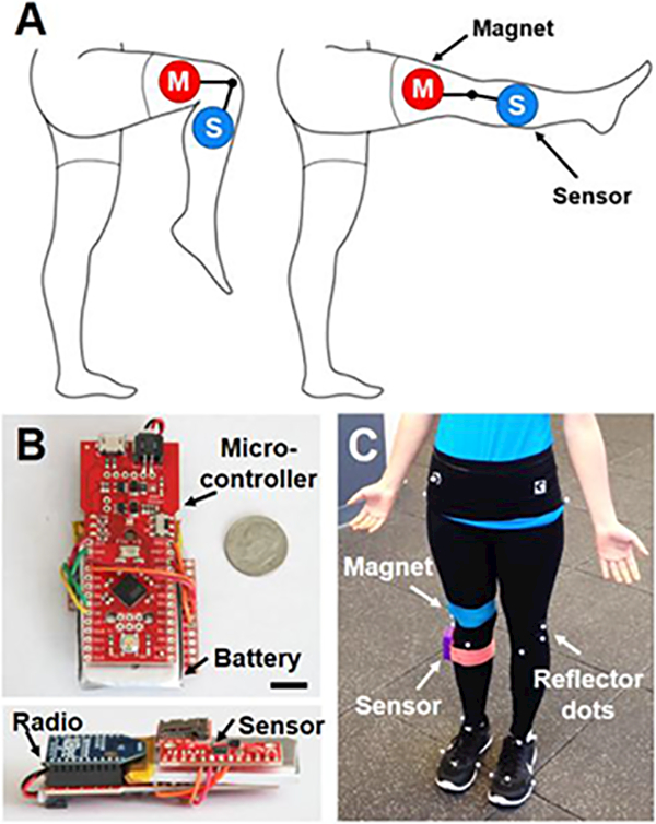
(A) Experimental schematic showing magnet (M) and sensor (S) placement on the lower extremity. (B) Top down and side views of the device hardware. Scale = 1 cm. (C) Magnet, sensor, and reflector dots attached to a human subject for gait analysis.
Angle Measurement:
To determine whether the system could detect changes in flexion angle, the device and a neodymium magnet were placed 15 cm equidistant from a hinge joint. Two magnets were tested: Weak (1.6 cm diameter, 0.5 cm thick; K&J Magnetics, Inc., Pipersville, PA) and Strong (2.5 cm diameter, 0.6 cm thick; K&J Magnetics, Inc.). The device was held stationary and the magnet moved to angles of 0, 45, 90, and 135° to simulate joint flexion. Position was held for 5 seconds at each angle (n=3 measurements/group) and the magnetic field strength was recorded.
To predict sensor-magnet angle as a function of magnetic field magnitude (the Euclidean norm of the three-dimensional vector), a geometry-dependent calibration curve was derived. To demonstrate proof of principle, the magnetic field of the Strong magnet was measured at 5° intervals from 0° to 135° for a fixed sensor-joint (10 cm) and magnet-joint (7.6 cm) distance (n=3 measurements/group), and a linear regression relating the magnetic field magnitude (M) to the inverse of the sensor-magnet distance (D) cubed was determined (Equation 1). D is related to the distance between the sensor and the joint (A), the distance between the magnet and the joint (B), and the angle between the sensor and the magnet (ϕ) by the law of cosines (Equation 2). Therefore, the angle between the magnet and the sensor (ϕ) can be derived by Equation 3.
| (Equation 1) |
| (Equation 2) |
| (Equation 3) |
The flexion angle (θ) is defined as the supplementary angle, or 180 - ϕ. A custom MATLAB (MathWorks, Natick, MA) program was used to calculate the magnetic field magnitude, generate the calibration curve, and derive the flexion angle for subsequent studies that involved different distance and magnet combinations. To determine full ROM, we used combinations that were sensitive enough to predict the angle at peak extension (far distance) without saturating the sensor at peak flexion (near distance).
Device Validation:
To determine the fidelity with which the device could capture joint flexion during normal gait, motion sensor data were synchronously collected with motion capture at 100 Hz. The dynamic ROM of the knee was measured in 3 healthy human subjects (26.7±3.5 years old, 22±1.5 body mass index) walking at a self-selected speed (1.3–1.5 m/s) in an IRB-approved study. A neodymium magnet (10 × 1.3 × 0.6 cm; K&J Magnetics, Inc.) and sensor were affixed 10 cm proximal and distal to the knee joint on the lateral aspect of the right leg, respectively, with self-adhesive wrap. The knee was held for 5 seconds at increasing flexion angles: 0°, 30°, 60°, and 70° (n=3–4 measurements/group). This calibration step was used to create a linear fit between the magnetic field at these angles and the inverse cube of the sensor-magnet distance, as previously described. From this, the relationship between magnetic field and flexion angle was derived and used to calculate joint angles in subsequent walking trials. In addition, the angular velocity of the tibia was extracted from gyroscope data in the sagittal plane.
At the same time, retro-reflective markers (9.5 mm; B&L Engineering, Santa Ana, CA) were adhered to the lower extremities and tracked using a 12-camera motion capture system (Raptor Series; Motion Analysis Corp., Santa Rosa, CA) (Fig. 1C). Markers were placed on the anterior and posterior superior iliac spines, greater trochanter of the femur, medial and lateral epicondyles, proximal tip of the fibular head, tibial tuberosity, medial and lateral malleoli, Achilles insertion into the calcaneus, and heads of the first and fifth metatarsal bones22. Knee flexion angle was calculated for a series of steps (n=10–32 steps/subject) using a constrained-kinematic model23 to determine the average ROM and peak flexion angle during the gait cycle, where knee flexion axis was defined as the tibial-femur rotation about the medial and lateral epicondyles (Visual3D; C-Motion, Inc., Germantown, MD). Angular velocity of the tibia during the gait cycle was calculated as the angular change of the tibia in the sagittal plane with respect to time using segmental measurements from this model (Visual3D; C-Motion, Inc). Data measured using motion capture and the sensor were compared using cross correlation analysis to establish the similarity in motion patterns between the measurement techniques24, where a Pearson’s correlation coefficient (rxy) of 1 indicates a perfect direct linear correlation between the two signals.
Animal Monitoring:
Activity of study animals was monitored using the wearable sensor in two configurations to quantify (1) general physical activity of the animal (n=5 animals) and (2) stifle flexion of the animal (n=1 animal). All animal procedures were approved by the Institutional Animal Care and Use Committee at the University of Pennsylvania.
To evaluate general activity in a large animal model, the device was attached to a harness worn on the back of 5 castrated male Yucatan mini-pigs (6 months old, ~30–35 kg; Sinclair Bioresources, Columbia, MO) pre- and post-surgery in an unrelated study involving bilateral arthrotomy of the stifle1,3 (Fig. 2A), where analgesics were administered for the first 5 days after surgery. Healthy animals were acclimated for 2 weeks pre-operatively to the device. These animals did not demonstrate visually detected gait or behavioral changes (e.g., attempting to remove the device) when wearing the device throughout the study. After a 10-minute acclimation period at each time point, data were collected for 30 minutes of unsupervised activity in a 1.2 × 1.8 m non-ferromagnetic stainless steel pen pre-operatively on Day −1 (Baseline), post-operatively on Day 1, and weekly thereafter until euthanasia at Week 10. Angular velocity (o/s) parallel to the dorsal plane (animal turning left or right) was recorded for 30 minutes at 100 Hz, resulting in 1.8 ×10⁵ data points per animal per timepoint. Angular velocity magnitude was binned into three activity intensity levels based on behavioral observations: 0–5 (Rest; recumbency), 5–50 (Low; low-impact activities such as eating and walking), or >50 (High; high-impact activities such as playing and trotting). Non-rest activity was defined as an angular velocity ≥5 o/s and used as a general marker of physical activity.
Fig. 2. Wearable device remotely monitors large animal activity and joint flexion in an unsupervised setting.
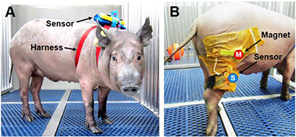
(A) Animal wearing the device dorsally inside a waterproof pouch to measure physical activity and (B) laterally affixed to the hind limb to assess stifle joint flexion. Magnet (M) and sensor (S) are secured to the hind limb with surgical adhesive drapes.
Functional recovery of the stifle joint was quantified using the device and magnet that were worn on the hind limb of one animal and discrete steps were extracted from regions of local maxima in the magnetic field data. The device and a neodymium magnet (2.5 cm diameter, 0.6 cm thick; K&J Magnetics, Inc.) were affixed to the lateral aspect of the right hind limb (10 cm proximal and distal to the stifle joint) of one animal and secured with a surgical adhesive drape (loban; 3M Company, Maplewood, MN) (Fig. 2B). These procedures were performed on a single animal to demonstrate feasibility and proof-of-principle of quantifying joint flexion. The animal was allowed a 10-minute period of acclimation before data collection. Data were collected pre-operatively (Baseline) and bi-weekly post-operatively during unsupervised activity as previously described. Discrete steps were identified by local maxima in the magnetic field (n=8–15 steps/time point) and used to determine the angular velocity of the tibia during the gait cycle. Stifle ROM was measured on Week 10 prior to euthanasia (n=10 steps) in conjunction with a high-speed video camera (Raspberry Pi Camera Module, 640×480 pixel resolution, 90 frames per second) that was synchronized with the wearable device to visually confirm that peaks in magnetic field, as detected by the sensor, corresponded to joint flexion. Immediately after euthanasia, the stifle was manually flexed to angles of 20° (maximum extension), 30°, 60°, and 90° to calibrate the device as previously described (n=3–4 measurements/group).
Statistical Analyses:
Statistical analyses were performed using SYSTAT (Systat Software, Inc., San Jose, CA). Significance was assessed by ANOVA with Tukey’s post-hoc tests or paired two-tailed t-tests to compare between groups, where a p-value ≤0.05 was considered significant. Magnet type (Strong vs. Weak) and their respective flexion angles were assessed by two-way ANOVA (p≤0.05). Joint flexion angles of human or animal hindlimbs were assessed by one-way ANOVA (p≤0.05). Paired two-tailed t-tests were used to compare range of motion and peak flexion angle measurements taken from the sensor and motion capture data for the human study (p≤0.05). Time points for Non-Rest Activity were assessed by one-way ANOVA for the animal study (p≤0.05). Data are presented as the mean ± standard deviation unless specified otherwise.
Results
Wearable magnet-based system measures joint flexion
The sensor detected changes in magnetic field strength when a neodymium magnet was positioned at various angles relative to a pivot point. Magnetic field values differed between all tested angles for both Weak and Strong magnets, with an inverse power law relationship (Fig. 3A, p<0.0001). The Strong magnet induced exponentially higher magnetic fields at each angle and was more sensitive to changes in position than the Weak magnet (Fig. 3A, p<0.0001 ). An equation based on the law of cosines and the inverse cube relationship between sensor-magnet distance and magnetic field (Equation 3) related the magnetic field strength to flexion angle (Fig. 3B-D, R2=0.9996), and this was used for calibrating subsequent studies.
Fig. 3. Magnet-based method for measuring flexion angle.
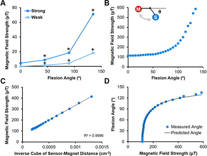
(A) Magnetic field strength as a function of flexion angle for Strong and Weak magnets placed 15 cm from hinge and sensor placed 15 cm from hinge (n=3 measurements/group). *=p≤0.05 vs. Strong, +=p≤0.05 vs. Weak and Strong. (B) Magnetic field strength as a function of flexion angle for Strong magnet placed 10 cm from hinge (sensor placed 7.6 cm from hinge) is used for calibration (n=3 measurements/group). Inset shows flexion angle (Θ) relative to magnet (M) and sensor (S) along a hinge joint. (C) The magnetic field strength is related to the inverse of the distance cubed, and (D) flexion angles are predicted using the law of cosines and compared to measured values.
Knee flexion angle during knee extension exercises and walking in humans was predicted by measuring changes in the magnetic field strength, which increased with flexion (Fig. 4A). Knee flexion measurements during normal gait cycles strongly correlated with motion capture findings (Fig. 4B, rxy=0.987). Knee ROM (68.8 ± 1.4° vs. 66.4 ± 3.7°, p=0.7507) and peak flexion angles (71.0 ± 0.4° vs. 69.2 ± 1.7°, p=0.1529) reflected motion capture measurements. Tibial angular velocity also agreed with motion capture measures, where angular velocity approached zero at peak flexion ( Fig. 4C, rxy=0.984).
Fig. 4. Wearable sensor-magnet system measures dynamic human joint flexion.
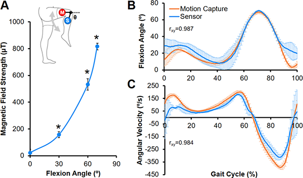
(A) Calibration curve showing the magnetic field strength as a function of knee flexion angle (Θ) (n=3–4 measurements/group). Inset depicts sensor (S) and magnet (M) placement on the lower extremity. *=p≤0.05 vs. all other angles. (B) Average knee flexion angle and (C) tibial angular velocity measured by the device and motion capture system during a normal human gait cycle (n=10–32 steps/subject, mean ± SEM). Pearson’s correlation coefficient (rxy) shows a positive correlation between measurements by the two systems.
Unsupervised monitoring demonstrates time course of recovery in a porcine model
Changes in animal activity pre-and post-arthrotomy were detected during unsupervised monitoring throughout the 10-week recovery period. On Day −1 (Baseline), animals were fully weight-bearing with no perceptible gait deficits, and activity was characterized by Rest (63.4%) and Low intensity activity (33.0%), with short periods of High intensity activity (3.6%) (Fig. 5). Post-operatively on Day 1, animals were predominately sedentary (92.5% Rest) and ambulated with a visibly stiff, limping gait, with non-rest activity reduced to 20.5% of the pre-operative level (Fig. 6B, p=0.003). By Week 1, the animals had regained 46.9% of Baseline activity (p=0.0195), and by Week 2, there was no significant difference compared to Baseline (p=0.9994). After Week 2, the average activity levels for the cohort remained at the Baseline level until sacrifice at Week 10, with distributions of Rest, Low, and High activity comparable to that of Baseline (Fig. 5B).
Fig 5. Sensor detection of unsupervised animal activity level before and after bilateral stifle arthrotomy.
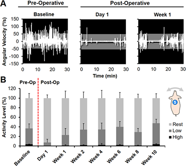
(A) Angular velocity (o/s) measured in the dorsal plane (animal turning left or right) for one animal pre-operatively at Day −1 (Baseline) and post-operatively at Day 1 and Week 1. Activity was divided into intensity levels of Rest (0–5 o/s, light gray), Low (5–50, dark gray), or High (>50, black) activity. (B) Distribution of average pre- and post-operative activity intensity for 5 animals over 10 weeks. Inset shows dorsal placement of the sensor (S).
Fig 6. Unsupervised activity monitoring demonstrates time course of recovery in a porcine model.
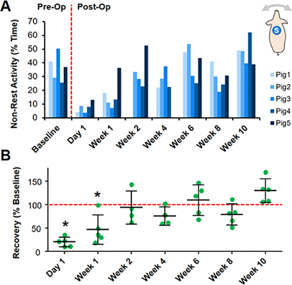
(A) % Non-rest activity before and after bilateral stifle arthrotomy for individual animals over a 10-week time course. Inset shows dorsal placement of the sensor (S). (B) Non-rest activity normalized to the average Baseline value (dashed line) for the entire cohort over 10 weeks. *=p<0.05 vs. Baseline.
At Week 10, the average ROM of the porcine stifle during the gait cycle was 55 ± 13°, with a peak flexion angle of 101 ± 4° (Fig. 7B). Altered ambulation was most apparent at Week 2, where the angular velocity of the tibia was reduced during the swing phase, indicating a stiffer gait (Fig. 7C). Although the angular velocity increased with time to approach the Baseline level, this deviation in ambulation was still detectable by Week 10.
Fig 7. Altered joint motion during unprovoked ambulation post-surgery.
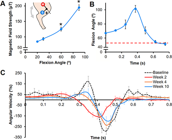
(A) Calibration curve showing magnetic field strength as a function of stifle flexion angle (Θ) (n=3–4 measurements/group). Inset depicts sensor (S) and magnet (M) placement on the hind limb. *=p≤0.05 vs. all other angles. (B) Average flexion angle during a gait cycle at Week 10 for one animal (n=10 steps, mean ± SEM). Red dashed line indicates neutral stance at standing rest. (C) Tibial angular velocity over a gait cycle pre-baseline) and post-surgery for one animal (n=8–15 steps/time point, mean ± SEM).
Discussion
Motion sensors can provide objective data for musculoskeletal research, especially for large animal models, where functional outcomes are difficult to measure. In this study, we established a wearable device capable of quantifying joint flexion in humans, and successfully translated it to a large animal model to detect changes to whole-body and joint-level function after arthrotomy. This paradigm facilitates remote, real-time visualization and analysis of unprovoked and unsupervised movement, setting the stage for more extensive deployment across species and applications in regenerative medicine.
Our findings demonstrate the feasibility of measuring joint flexion in both large animals and humans using a magnet-based detection system. By placing a magnet opposite the articulating joint, we identified discrete steps and calculated the dynamic ROM during ambulation in both the human knee and the porcine stifle. Joint function in the human and large animal arms of this study compared favorably with prior reports. Human knee ROM in the current study (68.8 ± 1.4°) was similar to other studies that used motion capture to quantify knee ROM (65–75o)25,26. Likewise, porcine stifle ROM (55 ± 13°) was consistent with previously reported values for healthy swine (43–68o)10. The novel application of a magnetometer and magnet demonstrate one of many possibilities provided by such low-cost sensors. While magnetometers have previously been exploited for spatial measurements, the Earth’s magnetic field was utilized as a reference, limiting the system to quasi-static measurements27,28. Others have used IMUs to calculate the attitude and heading of the sensor to provide descriptions of segment orientation29,30, but this approach requires two sensors to characterize joint angle, adding to the complexity of the system and implementation in animal studies.
Using our single-sensor system, we tracked the time course of recovery of a porcine cohort after bilateral arthrotomy and found that, while physical activity and gait were altered after surgery, animals returned to baseline activity within 2 weeks. Monitoring revealed substantial variability in the recovery rate between animals, highlighting the importance of assessing the activity of individuals over time. While we found significant changes to activity level at early time points post-operatively, extended monitoring periods may be required to capture subtle long-term differences. We also identified post-operative changes in the angular velocity of the tibia, indicating that gait abnormalities recovered slower than generalized activity. These data indicate that whole-body and joint function may improve at different rates and to different extents over time, and suggest joint-level measurements may be a more sensitive indicator of recovery. Although angular velocity does not describe the absolute joint angle, it does provide information on the motion patterns of the limb segment, such as relative ROM20. Determining the absolute ROM is more complicated, as the calibration step requires precise manipulation of the limb (performed post-euthanasia in the animal study). A more efficient technique to calculate joint angle may be to relate the magnetic field strength to limb position with respect to gravity, via the accelerometer.
Implementing this wearable magnet-based system for quantifying joint flexion has several strengths. The device does not require attachment to a power source to collect, store, and wirelessly transmit data, with the rechargeable battery lasting approximately 16 hours. This single-sensor setup is beneficial in large animal studies where test subjects may attempt to remove multiple sensors. Device performance can also be easily customized by adjusting the type, strength, and/or placement of the magnet. These joint monitoring systems can be implemented in future studies to elucidate the relationship between gait and pain, a clinically relevant outcome that is challenging to objectively evaluate in large animals.
Several limitations should be discussed when considering these study findings. To protect against the test subjects removing this device, we intentionally manufactured it using a robust plastic housing; however, future implementations could fit in much smaller housings based on application criteria. Care should be taken when acquiring measurements when the device is positioned near other ferrous materials. While the knee joint’s hinge-like motion is a good candidate for this measurement device, flexion does not fully define the position and orientation of the limb segments, and current work is focused on developing algorithms to quantify other knee motions, such as internal rotation and anterior translation31. In addition, more mobile joints, including the hip and shoulder, may not be easily quantified using the current approach. Furthermore, the device and magnet are placed near the knee joint, where considerable motion of the skin and soft tissue coverage occurs during walking26 and may induce measurement errors given that the magnetic field strength decays at a cubic rate. Dynamic stereoradiography32, bi-planar fluoroscopy26, and/or bone pins33 may be utilized in future validation studies to reduce motion artifact, although these techniques are expensive and not practical to implement in a traditional large animal research setting.
In conclusion, we demonstrated the potential utility of low-cost motion sensors for quantifying joint function in both human and large animal studies. Our magnet-based system revealed that joint flexion recovered to baseline levels at a slower rate than did overall activity level in this large animal study, suggesting that overall activity and joint-level function are discrete characteristics that should be evaluated independently. Understanding the extent and time course of abnormal joint motion is especially critical in orthopaedic tissue engineering, where joint loading can significantly affect cell behavior, matrix production, and tissue healing4,5. Future work will include employing machine learning algorithms to classify gait patterns (e.g., walk vs. trot34), as well as relate joint function to the structure and function of intra-articular tissues and implants13. The capability to correlate kinematic parameters to intra-articular markers of joint health, such as the gross and histological appearance of articular cartilage and other joint structures, would represent a significant advance for translational studies in tissue engineering as we seek to characterize the functional outcome of tissue engineered implants in vivo.
Acknowledgments
This work was supported by the NIH (T32 AR007132), the Penn Center for Musculoskeletal Disorders (P30 AR069619), and the Montague Research Award. The authors thank Drs. Emily L. Meidel, Christian G. Pfeifer, and James M. Friedman for their assistance with the large animal model.
Footnotes
Author Disclosure Statement
Feini Qu and Peter Gebhard are inventors on patent application US20170231533 and co-founders of Animotion, LLC. Feini Qu, Peter Gebhard, and Brendan Stoeckl have equity interest in Animotion, LLC, which is developing products related to the research described in this paper. All remaining co-authors have no competing financial interests.
References
- 1.Fisher MB, Belkin NS, Milby AH, Henning EA, Bostrom M, Kim M, Pfeifer C, Meloni G, Dodge GR, Burdick JA, Schaer TP, Steinberg DR, and Mauck RL. Cartilage repair and subchondral bone remodeling in response to focal lesions in a mini-pig model: Implications for tissue engineering. Tissue Eng. Part A 21:850–60, 2014. [DOI] [PMC free article] [PubMed] [Google Scholar]
- 2.Qu F, Pintauro MP, Haughan JE, Henning EA, Esterhai JL, Schaer TP, Mauck RL, and Fisher MB. Repair of dense connective tissues via biomaterial-mediated matrix reprogramming of the wound interface. Biomaterials 39:85–94, 2015. [DOI] [PMC free article] [PubMed] [Google Scholar]
- 3.Pfeifer CG, Kinsella SD, Milby AH, Fisher MB, Belkin NS, Mauck RL, and Carey JL. Development of a large animal model of osteochondritis dissecans of the knee: A pilot study. Orthop. J. Sports Med 3:2325967115570019, 2015. [DOI] [PMC free article] [PubMed] [Google Scholar]
- 4.Schatti O, Grad S, Goldhahn J, Salzmann G, Li Z, Alini M, and Stoddart MJ. A combination of shear and dynamic compression leads to mechanically induced chondrogenesis of human mesenchymal stem cells. Eur. Cell Mater 22:214–25, 2011. [DOI] [PubMed] [Google Scholar]
- 5.Ng JL, Kersh ME, Kilbreath S, and Knothe Tate M. Establishing the basis for mechanobiology-based physical therapy protocols to potentiate cellular healing and tissue regeneration. Front. Physiol 8:303, 2017. [DOI] [PMC free article] [PubMed] [Google Scholar]
- 6.Maher SA, Rodeo SA, Potter HG, Bonassar LJ, Wright TM, and Warren RF. A pre-clinical test platform for the functional evaluation of scaffolds for musculoskeletal defects: The meniscus. H.S.S. J 7:157–63, 2011. [DOI] [PMC free article] [PubMed] [Google Scholar]
- 7.Pfeifer CG, Fisher MB, Carey JL, and Mauck RL. Impact of guidance documents on translational large animal studies of cartilage repair. Sci. Transl. Med 7:310re9, 2015. [DOI] [PMC free article] [PubMed] [Google Scholar]
- 8.Bansal S, Keah NM, Neuwirth AL, O’Reilly O, Qu F, Seiber BN, Mandalapu S, Mauck RL, and Zgonis MH. Large animal models of meniscus repair and regeneration: A systematic review of the state of the field. Tissue Eng. Part C Methods 11:661–72, 2017. [DOI] [PMC free article] [PubMed] [Google Scholar]
- 9.Keegan KG, Dent EV, Wilson DA, Janicek J, Kramer J, Lacarrubba A, Walsh DM, Cassells MW, Esther TM, Schiltz P, Frees KE, Wilhite CL, Clark JM, Pollitt CC, Shaw R, and Norris T. Repeatability of subjective evaluation of lameness in horses. Equine Vet. J 42:92–7, 2010. [DOI] [PubMed] [Google Scholar]
- 10.Stavrakakis S, Guy JH, Warlow OM, Johnson GR, and Edwards SA. Longitudinal gait development and variability of growing pigs reared on three different floor types. Animal 8:338–46, 2014. [DOI] [PubMed] [Google Scholar]
- 11.Shin JH, Greer B, Hakim CH, Zhou Z, Chung YC, Duan Y, He Z, and Duan D. Quantitative phenotyping of duchenne muscular dystrophy dogs by comprehensive gait analysis and overnight activity monitoring. PLoS One 8:e59875, 2013. [DOI] [PMC free article] [PubMed] [Google Scholar]
- 12.Lascelles BD, Roe SC, Smith E, Reynolds L, Markham J, Marcellin-Little D, Bergh MS, and Budsberg SC. Evaluation of a pressure walkway system for measurement of vertical limb forces in clinically normal dogs. Am. J. Vet. Res 67:277–82, 2006. [DOI] [PubMed] [Google Scholar]
- 13.Cook JL, Smith PA, Bozynski CC, Kuroki K, Cook CR, Stoker AM, and Pfeiffer FM. Multiple injections of leukoreduced platelet rich plasma reduce pain and functional impairment in a canine model of acl and meniscal deficiency. J. Orthop. Res 34:607–15, 2016. [DOI] [PubMed] [Google Scholar]
- 14.Zumwalt AC, Hamrick M, and Schmitt D. Force plate for measuring the ground reaction forces in small animal locomotion. J. Biomech 39:2877–81, 2006. [DOI] [PubMed] [Google Scholar]
- 15.Evans R, Horstman C, and Conzemius M. Accuracy and optimization of force platform gait analysis in labradors with cranial cruciate disease evaluated at a walking gait. Vet. Surg 34:445–9, 2005. [DOI] [PubMed] [Google Scholar]
- 16.Keegan KG Evidence-based lameness detection and quantification. Vet. Clin. North Am. Equine Pract 23:403–23, 2007. [DOI] [PubMed] [Google Scholar]
- 17.Brown DC, Boston RC, and Farrar JT. Use of an activity monitor to detect response to treatment in dogs with osteoarthritis. J. Am. Vet. Med. Assoc 237:66–70, 2010. [DOI] [PMC free article] [PubMed] [Google Scholar]
- 18.Barthélémy I, Barrey E, Thibaud J-L, Uriarte A, Voit T, Blot S, and Hogrel J-Y. Gait analysis using accelerometry in dystrophin-deficient dogs. Neuromuscul. Disord 19:788–96, 2009. [DOI] [PubMed] [Google Scholar]
- 19.Keegan KG, Yonezawa Y, Pai PF, Wilson DA, and Kramer J. Evaluation of a sensor-based system of motion analysis for detection and quantification of forelimb and hind limb lameness in horses. Am. J. Vet. Res 65:665–70, 2004. [DOI] [PubMed] [Google Scholar]
- 20.Roepstorff L, Wiestner T, Weishaupt MA, and Egenvall E. Comparison of microgyro-based measurements of equine metatarsal/metacarpal bone to a high speed video locomotion analysis system during treadmill locomotion. Vet. J 198 Suppl 1:e157–60, 2013. [DOI] [PubMed] [Google Scholar]
- 21.Ladha C, O’Sullivan J, Belshaw Z, and Asher L. Gaitkeeper: A system for measuring canine gait. Sensors (Basel) 17:309, 2017. [DOI] [PMC free article] [PubMed] [Google Scholar]
- 22.Leardini A, Sawacha Z, Paolini G, Ingrosso S, Nativo R, and Benedetti MG. A new anatomically based protocol for gait analysis in children. Gait Posture 26:560–71,2007. [DOI] [PubMed] [Google Scholar]
- 23.Rajagopal A, Dembia CL, DeMers MS, Delp DD, Hicks JL, and Delp SL. Full-body musculoskeletal model for muscle-driven simulation of human gait. I.E.E.E. Trans. Biomed. Eng 63:2068–79, 2016. [DOI] [PMC free article] [PubMed] [Google Scholar]
- 24.Baxter JR, Sturnick DR, Demetracopoulos CA, Ellis SJ, and Deland JT. Cadaveric gait simulation reproduces foot and ankle kinematics from population-specific inputs. J. Orthop. Res 34:1663–8, 2016. [DOI] [PubMed] [Google Scholar]
- 25.Lafortune MA, Cavanagh PR, Sommer HJ 3rd, and Kalenak A. Three-dimensional kinematics of the human knee during walking. J. Biomech 25:347–57, 1992. [DOI] [PubMed] [Google Scholar]
- 26.Akbarshahi M, Schache AG, Fernandez JW, Baker R, Banks S, and Pandy MG. Non-invasive assessment of soft-tissue artifact and its effect on knee joint kinematics during functional activity. J. Biomech 43:1292–301, 2010. [DOI] [PubMed] [Google Scholar]
- 27.Bonnet S, and Héliot R. A magnetometer-based approach for studying human movements. I.E.E.E. Trans. Biomed. Eng 54:1353–5, 2007. [DOI] [PubMed] [Google Scholar]
- 28.O’Donovan KJ, Kamnik R, O’Keeffe DT, and Lyons GM. An inertial and magnetic sensor based technique for joint angle measurement. J. Biomech 40:2604–11,2007. [DOI] [PubMed] [Google Scholar]
- 29.Lebel K, Boissy P, Nguyen H, and Duval C. Autonomous quality control of joint orientation measured with inertial sensors. Sensors (Basel) 16:1037, 2016. [DOI] [PMC free article] [PubMed] [Google Scholar]
- 30.Favre J, Jolies BM, Aissaoui R, and Aminian K. Ambulatory measurement of 3d knee joint angle. J. Biomech 41:1029–35, 2008. [DOI] [PubMed] [Google Scholar]
- 31.Defrate LE, Papannagari R, Gill TJ, Moses JM, Pathare NP, and Li G. The 6 degrees of freedom kinematics of the knee after anterior cruciate ligament deficiency: An in vivo imaging analysis. Am J Sports Med 34:1240–6, 2006. [DOI] [PubMed] [Google Scholar]
- 32.Anderst WJ, Les C, and Tashman S. In vivo serial joint space measurements during dynamic loading in a canine model of osteoarthritis. Osteoarthritis Cartilage 13:808–16, 2005. [DOI] [PubMed] [Google Scholar]
- 33.Benoit DL, Ramsey DK, Lamontagne M, Xu L, Wretenberg P, and Renstrom P. Effect of skin movement artifact on knee kinematics during gait and cutting motions measured in vivo. Gait Posture 24:152–64, 2006. [DOI] [PubMed] [Google Scholar]
- 34.Olsen E, Andersen PH, and Pfau T. Accuracy and precision of equine gait event detection during walking with limb and trunk mounted inertial sensors. Sensors (Basel) 12:8145–56, 2012. [DOI] [PMC free article] [PubMed] [Google Scholar]


