

Summary
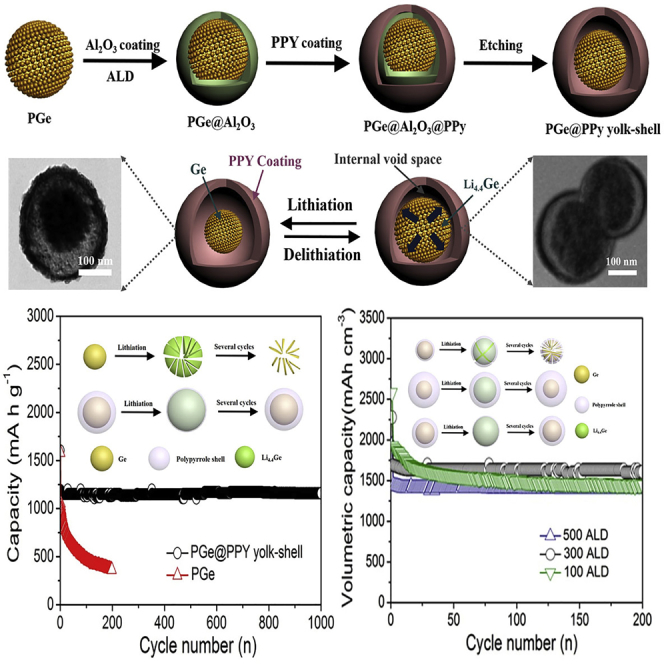
The key properties of yolk-shell architecture in improving electrochemical performance lies in its uniformity and the appropriate void space, which can expand/contract freely upon lithium alloying and leaching without damaging the outer shell, while being achievable with minimal sacrifice of volumetric energy density. Therefore, we developed a highly controllable strategy to fabricate a uniform porous germanium@polypyrrole (PGe@PPy) yolk-shell architecture with conformal Al2O3 sacrificial layer by atomic layer deposition (ALD) process. The PGe@PPy yolk-shell anode fabricated with 300 ALD cycles delivers excellent electrochemical performance: high reversible capacity (1,220 mA hr g−1), long cycle performance (>95% capacity retention after 1,000 cycles), and excellent rate capability (>750 mA hr g−1 at 32 A g−1). Electrodes with high areal capacity and current density were also successfully fabricated, opening a new pathway to develop high-capacity electrode materials with large volume expansion.
Subject Areas: Nanoparticles, Nanoelectrochemistry, Materials Science, Energy Materials
Graphical Abstract
Highlights
-
•
Porous germanium@polypyrrole (PGe@PPy) yolk-shell architecture was developed
-
•
Precision expansion and void control make PGe@PPy stable during lithiation/delithiation
-
•
PGe@PPy electrode shows high rate and areal capacity, cycling stability, and current density
-
•
The full cell shows the stable capacity retention with high energy density
Nanoparticles; Nanoelectrochemistry; Materials Science; Energy Materials
Introduction
There has been a rapid increase in the demand for rechargeable lithium-ion batteries (LIBs) with long cycling lifetimes and high energy and power densities for next-generation advanced energy storage devices such as advanced portable electronics and fast-developing electric vehicles (Armand and Tarascon, 2008, Kang et al., 2006). Owing to the limitation of the commercial graphite anode (theoretical capacity of only 372 mA hr g−1), the demands for next-generation batteries with high energy and power densities cannot be met (Guo et al., 2008, Tarascon and Armand, 2001). Toward this aim, a large variety of anode materials for rechargeable batteries have been explored, mainly including oxides (e.g., Fe3O4, GeO2, and SiOx) and alloys (e.g., Sb, Sn, and Ge), owing to their high theoretical capacities and safe operation potential (Song et al., 2017, Sultana et al., 2017, Kim et al., 2018, Wang et al., 2017, Lei et al., 2018, Yuan et al., 2018). Among these materials, germanium (Ge) is a potential candidate to replace the commercial graphite anode for LIBs because of its high gravimetric and volumetric capacities (1,626 mA hr g−1 and 7,360 mA hr cm−3), low electrochemical potential of Li insertion/extraction (<0.5 V vs Li+/Li), excellent lithium diffusivity (400 times faster than in Si), and higher intrinsic electrical conductivity compared with Si. Despite these promising characteristics, the inferior structure stability due to the huge volume expansion (ca. 300% volume change for fully lithiated Ge) would result in the rapid capacity fade of the Ge-based electrode accompanied by a large irreversible capacity similar to Si, hindering the practical implementation of Ge anodes in future technological applications (Seng et al., 2012, Yuan et al., 2012, Cho et al., 2013).
To tackle this problem, two main strategies have been used to stabilizing the material structure and improving the electrochemical performance of Ge anodes by design of various nanostructures and electronically conductive coatings. Recently, the design of various nanostructures, such as nanowires (Liu et al., 2014, Seo et al., 2011, Kennedy et al., 2015), nanotubes (Liu et al., 2015a, Liu et al., 2015b, Song et al., 2012, Xiao et al., 2016), and porous structures (Park et al., 2010, Liu et al., 2015a, Liu et al., 2015b), has attracted great attention. Particularly, Park and co-workers rationally designed a porous germanium architecture, which induces only a 2% capacity decrease after 100 cycles (Park et al., 2010). The porous nanostructure materials show excellent cycle stability and rate capability because the uniform pores also act as a buffer to effectively alleviate the volume expansion and provide favorable structural stability during the lithiation/delithiation process (Park et al., 2010). Besides design of nanostructure strategies, electronically conductive coatings on Ge anode structures have been explored (Li et al., 2014, Ngo et al., 2014, Ngo et al., 2015, Wang et al., 2016, Seng et al., 2013). In this respect, Park and co-workers developed a facile method for the synthesis of Ge interconnected by a carbon buffer layer, which works as a channel for the supply of lithium during the charge-discharge process (Ngo et al., 2015). However, this strategy does not provide appropriate void space to alleviate the huge volume changes during lithium alloying and leaching and results in the pulverization, exfoliation, and aggregation of electrode materials. Very recently, yolk-shell architecture has attracted much attention in many fields, particularly in the field of energy storage (Zhang et al., 2016, Liu et al., 2012, Cai et al., 2015, Hong et al., 2013). The key design of the yolk-shell architecture in improving electrochemical performance lies in the ideal void space, which would be expanding/contracting freely upon lithium alloying and leaching without damaging the outer shell and, more importantly, be achieved with a minimal sacrifice of volumetric energy density. It is noteworthy that the volumetric capacity is an important indicator for the commercialization of electrode materials. If the void space is too much, even in the fully lithiated state, the core will not touch the shell, leading to the decrease of the volumetric capacity of the electrode. In addition, electrically conducting polymers such as polypyrrole may form a conducting elastic matrix, which offers a conducting backbone for the electrode material, and it could also be used as a flexible host matrix of electrode material to alleviate the huge volume changes during lithium alloying and leaching. Therefore, it remains a challenge to develop a facile approach for the synthesis of uniform yolk-shell architecture with the incorporation of the ideal void space and robust conducting polymer coating for the high volumetric capacity and long-cycle LIBs.
It is noted that a conformal, homogeneous, and controllable nature of the sacrificial coating layer is crucial for appropriate void space of the yolk-shell architecture. Atomic layer deposition (ALD) is a technique to apply conformal, homogeneous, and controllable coating on high-surface nanostructures as the sacrificial layer by sequential, self-limiting surface reactions (George et al., 1996, George, 2010). Here, we developed a facile and highly controllable approach to uniform porous germanium@polypyrrole (PGe@PPy) yolk-shell architecture with conformal and controllable Al2O3 sacrificial layer by the ALD technique. There are several advantages of the yolk-shell architecture as anode material: (1) The presence of appropriate void space to alleviate the huge volume changes during lithium alloying and leaching, thus maintaining the structural stability of the outer shell to avoid the pulverization of electrode materials, and also achieved with a minimal sacrifice of volumetric capacity. (2) Recently, the inner relationship between the stability of the solid/electrolyte interphase (SEI) and the electrochemical properties of LIBs has been studied (Wu et al., 2012), which indicated that the SEI formed around the PPy shell during the cycles can be stable because the fully lithiated state of Ge core cannot damage the PPy outer shell. (3) The conductivity and stability can be improved for the yolk-shell architecture because the PPy outer shell has outstanding properties, including excellent chemical stability, electronic conductivity, and structural flexibility. Insight gained from this study can be applied to other high-capacity electrode materials, particularly those that suffer from huge volume expansion, offering a route for the future development of the promising electrode material for practical applications.
Results
As shown in Figure 1A, the fabrication the of PGe@PPy yolk-shell architecture is relatively simple and involves four consecutive steps. First, uniform mesoporous GeO2 nanospheres (MGeO2) with ordered and radially oriented mesoporous channels were prepared via the emulsification process, by using cetyltrimethyl-ammonium bromide as the mesoporous structure-directing agent (Figures S1A and S1B, Supplemental Information). Specifically, Ge4+ ions were added afterward into the GO-CTA+ solution and rapidly reacted with OH− to form negatively charged Ge(OH)x at the interface of the micelles (Wang et al., 2010, Teng et al., 2012). Second, PGe was generated through the reduction of MGeO2 under vacuum and thermally annealed at 650°C for 6 hr under an atmosphere of Ar (90%)/H2 (10%). In the reduction process, the PGe nanosphere generated by reduction has a porous structure; the diameter of the pore scaffolds is ∼13.6 nm (Figure S2, Supplemental Information) (Li et al., 2013). Third, the PGe is coated with Al2O3 as the sacrificial coating layer using ALD. We employed a simple, well-known ALD process utilizing trimethylaluminum and H2O as precursors (Jung et al., 2010):
| (a) AlOH∗+Al(CH3)3→AlO-Al(CH3)2∗+CH4 | (Equation 1) |
| (b) AlCH3∗+H2O→Al-OH∗+CH4 | (Equation 2) |
Figure 1.

Schematic Illustration of Synthesis and Characterization of As-prepared PGe@PPy Yolk-Shell Architecture
(A) Schematic illustration of the preparation of PGe@PPy yolk-shell architecture.
(B and C) FESEM images of the MGeO2 nanosphere and PGe@PPy yolk-shell architecture.
(D and E) TEM images of the MGeO2 nanosphere and PGe@PPy yolk-shell architecture.
(F) Scanning TEM (STEM) image.
(G) Energy dispersive x-ray spectroscopy (EDS) elemental maps of Ge, C, N, and O, respectively.
(H and I) (H) XRD patterns and (I) Raman spectra of the PGe@PPy yolk-shell architecture.
Then the PGe@Al2O3 nanospheres were dispersed in distilled water and then wrapped by a soft layer of Polyvinyl pyrrolidone (PVP). PVP was used to bridge the PPy and PGe, ensuring a stable connection. The polymerization of pyrrole monomers initiated by FeCl3 oxidant occurred between the region of the PVP layer and the PGe, resulting in the formation of PGe@Al2O3@PPy nanocomposite. As a final step, acid etching was then used to remove the Al2O3 sacrificial layer to leave only the PGe@PPy yolk-shell architecture.
To investigate the morphology of the as-prepared PGe@PPy yolk-shell architecture, field-emission scanning electron microscopy (FESEM) was performed, and a typical image is shown in Figure 1B. It can be observed that the MGeO2 nanoparticles are spherical and uniform, giving an average diameter of approximately 150 nm (Figure 1D). As determined by N2 adsorption-desorption analyses, the Brunauer-Emmett-Teller surface area of the MGeO2 is approximately 362 m2 g−1 and the Barrett-Joyner-Halenda (BJH) pore-size distribution is about 2.8 nm in diameter (Figure S1C, Supplemental Information). The PGe generated by the thermal reduction still maintains at an average diameter of ∼150 nm (Figure S2C, Supplemental Information). Moreover, the BJH pore-size distribution is ∼13.6 nm in diameter (Figure S2B, Supplemental Information). Figure 1C shows the FESEM image of the as-obtained PGe@PPy yolk-shell architecture, which clearly reveals the architecture is spherical and uniform, giving an average diameter of ∼230 nm. To further examine the structure of the PGe@PPy yolk-shell architecture, the uniform morphologies were investigated by transmission electron microscopy (TEM). As shown in Figure 1E, each PGe nanosphere is encapsulated by a self-supporting PPy outer shell with a uniform thickness of 15–20 nm, which can be limiting SEI formation to the outer shell surface. The direct contact of the PGe core with the electrically and lithium ion conductive PPy shell makes the core more accessible to both charge carriers. The hollow interior of the architecture is clearly revealed under TEM observation (Figure 1F). Inside, the PGe core, about 150 nm in diameter, is closely attached to one side of the PPy shell, leaving a ∼66-nm void space on the other side, which is consistent with the 300 ALD cycles (1.1 Å per cycle). In this work, this ALD cycle is calculated mainly through this diameter ratio (ca. 1:1.45) based on the volume ratio of PGe and fully lithiated PGe (ca. 1:3). Moreover, the element mapping in Figure 1G further confirms the yolk-shell architecture with PGe as the core, PPy as the shell, and the void space in between. It need be noted that oxygen signals cover the entire sample area, attributing to the surface oxidation of the PGe nanospheres. In addition, to study the influence of porous nanostructure and PPy yolk-shell architecture on the electrochemical performance, the pure porous Ge nanosphere was also synthesized by using the same procedure, without adding any coating Al2O3 ALD layer and PPy (Figure S2, Supplemental Information).
X-ray diffraction (XRD) is employed to determine the crystallographic phases of the samples (Figure 1H). The phase purity of the as-prepared PGe@PPy yolk-shell architecture is also confirmed, where all the diffraction peaks can be perfectly assigned to diamond-like cubic Ge (JCPDS No. 04-0545) (Lim et al., 2015), indicating that GeO2 is successfully converted into Ge by the reduction reaction. Although the presence of residual PPy in the sample was not evidenced by the XRD results, its existence was confirmed by Raman scattering (Figure 1I). The appearance of the strong peak at 1,588 cm−1 and weak peaks at 981 cm−1 and 927 cm−1, which are assigned to C=C backbone stretching and ring-in plane deformation of PPy, respectively, indicates the successful polymerization of polypyrrole (Liu et al., 2013). The very sharp peak observed at 297 cm−1 was assigned to crystalline Ge (Xiao et al., 2012). In addition, Figure S3 shows the thermal gravimetric analysis (TGA) curves of composites to determine the exact mass ratio of PGe in the PGe@PPy yolk-shell architecture. The mass of the PGe component increased slightly at 700°C owing to the oxidation of Ge; the mass of the PPy component had been completely lost (total of 99.7%) at 700°C. These TGA data enable the mass ratio of PGe to PPY to be determined from the mass difference of PGe, PPy, and PGe@PPy yolk-shell architecture, therefore 84.37 wt% of PGe and 15.63 wt% of PPy (Table S1, Supplemental Information).
The successful design and fabrication of the PGe@PPy yolk-shell architecture as a stabilized anode is proved from the outstanding electrochemical property (Figure 2). The electrochemical performance of the PGe@PPy yolk-shell electrode with 300 ALD cycles was first evaluated by galvanostatic charge-discharge measurements in the 0.01- to 1.5-V voltage window (Figure 2A). The voltage profile with different flat plateaus due to the redox reactions associated with Li+ insertion/extraction can be observed in the first discharge and charge curves. In the first cycle, the PGe@PPy yolk-shell electrode is able to exhibit a high first-cycle columbic efficiency in contrast to a large irreversible capacity loss observed in the first cycle for the PGe electrodes. The discharge (Li insertion) and charge (Li extraction) capacities of the PGe@PPy yolk-shell are 1,604 and 1,220 mA hr g−1, respectively, corresponding to a first-cycle efficiency of 76.06%, which is higher than that (62.28%) for PGe particle. The irreversible capacity ratio can be assigned to the decomposition of electrolyte, forming an SEI on the electrode surface, and to the irreversible insertion of Li ions into the Ge (Pan et al., 2007, Lee et al., 2005). To better understand the electrochemical process of the lithiation, Figures 3A and 3B show a series of Raman spectra of the PGe@PPy yolk-shell electrode in the working battery during lithiation. Figure 3A shows the schematic of the electrochemical cell. The cells were assembled using a PGe@PPy yolk-shell electrode with 300 ALD cycles, lithium sheet as the counter electrode, and a Celgard separator soaked in electrolyte. The first Raman spectrum was collected before the lithiation began, in which the first-order Raman peak observed at 297 cm−1 was assigned to crystalline Ge (see Figure 3B). The other Raman peaks spring from either the cell-encapsulating material or the electrolyte. The intensity of the Ge Raman peak is maintained sharp in the first 5 hr, followed by the decline in intensity during the process of further lithiation. The electrochemical process of Ge anodes can be determined by the change of Raman peak intensity. As mentioned earlier, Ge anodes remain unreacted at the beginning, which explicates the steady Raman peak intensity of Ge nanoparticles during this stage. When the lithiation of Ge electrode starts after 5 hr, the surface layer of Ge nanoparticles is converted into a-LixGe, which exhibits better conductivity than Ge. The good conductivity of a-LixGe leads to a small optical skin depth (penetration depth of the laser), which explicates the reduction of Ge Raman peak intensity. Simultaneously, the intensities of the Raman peaks of the cell-encapsulating material or the electrolyte are almost constant, demonstrating that the change of the Ge Raman peak intensity is associated with the electrochemical process of the lithiation.
Figure 2.

Electrochemical Performance of PGe@PPy Yolk-Shell Electrode
(A–F) (A) Galvanostatic charge-discharge profiles in the 0.01- to 1.5-V window (versus Li/Li+) for the 1st, 2nd, 5th, 100th, and 1,000th cycles at 0.8 A g−1; (B) cycling performance (discharge) and coulombic efficiency of the PGe@PPy yolk-shell (black) and PGe (red) electrodes with mass loading of 1 mg cm−2 at 0.8 A g−1 for 1,000 cycles; (C) and (D) cycling performance (gravitational capacity and volumetric capacity, respectively) of the PGe@PPy yolk-shell electrodes with the 100, 300, and 500 ALD cycles at 0.8 A g−1 for 200 cycles; (E) rate performance of the PGe@PPy yolk-shell and PGe electrodes with mass loading of 1 mg cm−2 at different current densities; and (F) Nyquist plots of the PGe@PPy yolk-shell electrode after the 1st, 2nd, 5th, 100th, and 1,000th cycles at a current density of 0.8 A g−1.
Figure 3.

Understanding of Lithiation Mechanism and Morphological Changes of the PGe@PPy Yolk-Shell Electrode
(A) Schematic diagram of the “transparent” half-cell for in situ micro-Raman measurement.
(B) Selected Raman spectra of the half-cell during galvanostatic lithiation of the PGe@PPy yolk-shell architecture for the second cycle at a rate of C/10. A laser power of 2.5 mW and a collection time of 30 s were used for each spectrum; for each acquisition 10 spectra were accumulated.
(C–E) FESEM (C and D) and TEM (E) images of the PGe@PPy yolk-shell electrode in lithium lithiation state after 1,000 cycles at a current density of 0.8 A g−1.
(F) Schematic drawing of the charge-discharge processes of the PGe@PPy yolk-shell electrode.
To confirm the lithium storage mechanism of the PGe@PPy yolk-shell architecture, cyclic voltammetry was obtained in a voltage window of 0.05–2.0 V at a scan rate of 0.1 mV s−1, as shown in Figure S4. In the first scanning cycle, the PGe@PPy yolk-shell electrode showed irreversible reductions at 1–0.5 V, which can be ascribed to the formation of a SEI layer. There are three peaks detected in the range between 0.7 and 0.05 V, which can be assigned to the lithium alloying reactions to form different LixGey alloys (Park et al., 2010, Yuan and Tuan, 2014), whereas the peaks between 0.30 and 0.75 V in the oxidation scan can be related to the phase transition of different LixGey alloys to Ge due to dealloying reactions from Ge. In the subsequent scanning cycles, the positions and intensities of the redox peaks are well overlapped, implying that the PGe@PPy yolk-shell architecture has an excellent electrochemical reversibility.
Remarkably, the PGe@PPy yolk-shell electrode with 300 ALD cycles has a long cycle life (Figure 2B). The shape of the profile does not change from the 10th to the 1,000th cycle, indicating stable electrochemical behavior of the PGe@PPy yolk-shell. On the other hand, the PGe electrode exhibits a drastic reduction, up to approximately 100 cycles, and a lower discharge capacity of 365 mA hr g−1 over 200 cycles. It is obvious that the PGe@PPy yolk-shell electrodes with 300 ALD cycles are distinctly superior to the corresponding PGe electrodes. It is worth noting that the average coulombic efficiency reaches approximately 99.8% during the 1,000 cycles. In addition, after 200 cycles, reversible capacities around 863 and 722 mA hr g−1 could be obtained at higher current densities of 16 and 32 A g−1 (Figure S5, Supplemental Information). Furthermore, the volumetric capacity is an important indicator for the commercialization of electrode materials (Yuan and Tuan, 2014). The PGe@PPy yolk-shell architecture has a high tap density of 1.42 g cm−3 because of the appropriate void space. The composite still retained a volumetric capacity of ca. 1,692 mA h cm−3 at a rate of 0.8 A g−1 over 1,000 cycles, which is two times more than that of the commercial graphitic anode (830 mA hr cm−3) (Wang et al., 2014, Kim et al., 2014, Baggetto et al., 2008). For comparison, PGe@PPy yolk-shell architectures with different thickness of void space were also synthesized by using the same experimental condition with 100 and 500 ALD cycles, respectively (Figure S6, Supplemental Information). It is clear from the TEM image that the architecture leaves a 22- and 110-nm void space, which is consistent with the 100 and 500 ALD cycles (1.1 Å per cycle). This ALD cycle is very critical because it determines the internal void space (that is, Al2O3 sacrificial layer) between the PPy shell and PGe core. Moreover, the electrochemical performance of the PGe@PPy yolk-shell electrodes with the 100, 300, and 500 ALD cycles was tested (as shown in Figures 3C and 3D). Remarkably, the PGe@PPy yolk-shell electrode with 300 and 500 ALD cycles has a long cycle life (Figure 2C). The shape of the profile does not change from the 10th to the 200th cycle, indicating stable electrochemical behavior of the PGe@PPy yolk-shell electrode with 300 and 500 ALD cycles. On the other hand, the PGe@PPy yolk-shell electrode with 100 ALD cycles exhibits a drastic reduction and a lower discharge capacity of 885 mA hr g−1 over 200 cycles. This result may be ascribed to the thin void space, which may crack or disintegrate upon the lithiation/delithiation process, resulting in the rapid capacity to fade of the electrode. Furthermore, the tap density of the PGe@PPy yolk-shell architecture with 100, 300, and 500 ALD cycles was 1.61, 1.42, 1.21 g cm−3, respectively. It is indeed noteworthy that the volumetric capacity of the PGe@PPy yolk-shell architecture obtained by 300 (1,692 mA hr cm−3) and 100 ALD cycles (1,425 mA hr cm−3) at a current density of 0.8 A g−1 over 200 cycles is higher than that obtained by 500 ALD cycles (1395 mA hr cm−3). This result may be ascribed to the thick void space; even in the fully lithiated state, the PGe core will not touch the shell, leading to the decrease of the volumetric capacity of the electrode. Therefore, the electrochemical performance of the PGe@PPy yolk-shell electrode with 300 ALD cycles is more excellent, which may not only effectively buffer the strain from the volume expansion/contraction during the charge-discharge process and restrain the aggregation of PGe nanostructure but also be achieved with a minimal sacrifice of volumetric energy capacity (Figure S7, Supplemental Information).
The rate capability of the PGe@PPy yolk-shell electrode with 300 ALD cycles was tested at different current densities for each of the 10 cycles. The obtained results are shown in Figure 2E. The reversible capacity of the PGe@PPy yolk-shell was 1,186, 1,132, 1,078, 991, 882, and 753 mA hr g−1 at rates of 0.8, 1.6, 3.2, 8, 16, and 32 A g−1, respectively. Subsequently, the current densities were brought back to an initial value of 0.8 A g−1 at which the specific capacity reached a value of 1,176 mA hr g−1 and therefore almost recovered. This value is close to the capacity of the first 10 cycles at this rate. After undergoing the high current density, the capacity rapidly returned to the initial value, indicating the excellent rate capability of the sample. It is remarkable that all the electrochemical data were calculated based on the total mass of the composite, including PPy and germanium, in this work. Furthermore, the excellent high-rate performance is attributed to the substantial decrease in charge-transfer resistance due to the PGe@PPy yolk-shell architecture. The Nyquist plots of electrodes of PGe and PGe@PPy yolk-shell electrode with 300 ALD cycles were also studied (Figure S8, Supplemental Information). Apparently, the PGe@PPy yolk-shell electrode shows a much lower resistance than the pure PGe electrode. Obviously, PPy acts as a channel for lithium to Ge during the insertion/desertion process owing to the high diffusion coefficient of polypyrrole compared with germanium. Therefore, in the presence of PPy shell, the lithium diffusion can be faster and the conductivity and rate capability can be improved.
To understand the superior cycling performance, electrochemical impedance spectroscopy (EIS) measurements of the PGe@PPy yolk-shell electrode with 300 ALD cycles were conducted after the 1st, 2nd, 5th, 100th, and 1,000th cycle at a current density of 0.8 A g−1 (Figure 2F). No obvious resistance increase is observed upon cycling, indicating the structural stability of the yolk-shell architecture. As confirmed by FESEM and TEM observations of the PGe@PPy yolk-shell electrode with 300 ALD cycles in lithiation state after 1,000 cycles (Figures 3C–3E), the spherical morphology and yolk-shell structure of the PGe@PPy architecture are well retained (Figures 3C and 3D). The TEM image of a lithiated yolk-shell architecture shows a structurally intact PPy coating (Figure 3E), indicating that the PGe core can expand/contract freely upon lithiation/delithiation without breaking the PPy shell. Moreover, there was little change in the thickness of electrode before and after 1,000 cycles at a current density of 0.8 A g−1 (Figure S9, Supplemental Information), which further confirms the ability of the yolk-shell design in alleviating the huge volume expansion/contraction during the charge-discharge process. This result clearly indicates that, to avoid nanostructure agglomeration and effectively accommodate the significant volume expansion/contraction, Li-Ge alloying and de-alloying reactions are key factors for a high reversible capacity, long cycle stability, and excellent rate capability (Figure 3F). Table S2 is the comparison of the cycle and rate performance of various Ge-based composites prepared by different structural designs in the available literature, indicating that the specific capacity under long-cycle and high-rate testing is one of the most challenging issues for promoting high-performance Ge-based LIB application.
It is also generally essential to study the high areal mass loading of the PGe@PPy yolk-shell electrode for practical LIBs. Figures 4A and 4B further show the effect of both areal mass loading and areal current density on the areal capacity of the PGe@PPy yolk-shell electrode. The areal capacity linearly increases with mass loading when the current density is less than 8 A g−1; further increasing the current density (e.g., 32 A g−1) deviates the linear relationship at high mass loading (e.g., 6 mg cm−2) owing to the increased charge resistance and the less effective utilization of the active material. To further assess the performance of the PGe@PPy yolk-shell electrode, Figure 4A also marks the areal capacities of commercial graphite anodes, which are in the range of 2.5–3.5 mA hr cm−2 when operated at a current-density range of 0.37–1.86 mA cm−2 (Wang et al., 2018). As shown, the PGe@PPy yolk-shell electrode with a mass loading of 6 mg cm−2 exhibits areal capacity as high as 6.0, 5.5, 4.8, and 3.8 mA hr cm−2 at a charge-discharge current density of 0.8, 1.6, 3.2, and 8.0 A g−1, respectively. Compared with the areal capacities of commercial graphite anodes, the areal capacities of the PGe@PPy yolk-shell electrodes are significantly higher, particularly, at high current density.
Figure 4.

Performance of the PGe@PPy Yolk-Shell Electrodes with Various Mass Loadings
(A) The correlation of areal capacity with mass loading (1, 3, and 6 mg cm−2) at various current densities for the PGe@PPy yolk-shell electrode. The gray area marked in (A) represents the range of the areal capacity of common commercial anodes.
(B) The effect of current density and mass loading (1, 3, and 6 mg cm−2) on the areal capacity of the PGe@PPy yolk-shell electrode.
(C) Utilization of the active material of the PGe@PPy yolk-shell electrode with various mass loading at different current densities.
(D) Nyquist plots of the PGe@PPy yolk-shell electrode under different mass loadings (1, 3, and 6 mg cm−2).
Figure 4C further plots the utilization of the active material versus the current density, of which the utilization is estimated by normalizing the specific capacity of the electrode at different current densities (the slopes of the lines) versus the specific capacity at 0.8 A g−1. The utilization decreases with increasing mass loading and current density, which is 95%, 91%, and 90% at 1.6 A g−1 or 90%, 83%, and 81% at 3.2 A g−1 for the electrodes with a mass loading of 1, 3, and 6 mg cm−2, respectively. It was found that increasing mass loading from 1 to 6 mg cm−2 only reduces the utilization for ∼10% even at a high charge-discharge current density of 8 A g−1. To understand the excellent electrochemical properties of the PGe@PPy yolk-shell electrode under high areal mass loading, EIS measurements of these electrodes were also studied (Figure 4D). Here, the PGe@PPy yolk-shell electrodes with different areal mass loadings exhibit low charge-transfer resistance. These studies further confirm the high electrochemical performance of the high-mass-loading PGe@PPy yolk-shell electrodes.
To demonstrate the relevance of PGe@PPy as a promising high-capacity anode for LIB, a full cell consisting of commercial LiNi1/3Co1/3Mn1/3O2 cathode and the PGe@PPy anode was fabricated. The areal capacity ratio between negative and positive electrodes (N/P ratio) was 1.12. Before assembly of the full cell, the PGe@PPy anode was electrochemically prelithiated to minimize irreversible capacity.
As shown in Figure 5A, a high reversible capacity of 139 mA hr g−1 was shown in the first galvanostatic charge/discharge voltage profiles of the full cell at 0.1 C in the potential range 2.5 to 4.25 V. Compared with the ICE of PGe@PPy half-cell (76%), the higher ICE of full cell (82%) was obtained, which may be attributed to the prelithiation process. Figures 5B and 5C exhibit the stability of the full cell over 100 cycles at a rate of 0.5 C, and the stable capacity retentions of 90% were obtained after 100 cycles. In addition, the full cell showed a high energy density of ∼410 W hr kg, which is much higher than that of the commercial LIBs.
Figure 5.

Electrochemical Properties of a LiNi1/3Co1/3Mn1/3O2/PGe@PPy Full Cell
(A) Galvanostatic first-cycle discharge-charge voltage profiles at 0.2 C in a potential window of 2.5–4.25 V.
(B) Galvanostatic charge-discharge profiles in the 0.01- to 1.5-V window for the 1st, 2nd, 5th, 50th, and 100th cycles at 0.5 C.
(C) Cycling performance (red) and energy density (blue) of the LiNi1/3Co1/3Mn1/3O2/PGe@PPy full cell at 0.5 C for 100 cycles.
Discussion
In summary, a facile and general strategy has been proposed to fabricate a uniform porous germanium@ polypyrrole (PGe@PPy) yolk-shell architecture with a conformal and controllable Al2O3 sacrificial layer by the ALD process. A rationally designed void space between the shell and the core allows for the free expansion/contraction of Ge upon lithiation/delithiation without destroying the PPy outer shell or disrupting the SEI on the outside surface. Hence the PGe@PPy yolk-shell electrode with 300 ALD cycles exhibits a high specific reversible capacity (1,220 mA hr g−1), long cycle stability (over 94% capacity retention after 1,000 cycles), excellent rate capability (over 750 mA hr g−1 at 32 A g−1), and coulombic efficiency (99.8%). Toward the practical use, electrodes with high areal capacity and current density (e.g., 6.0 mA hr cm−2 at 0.8 A g−1, 5.5 mA hr cm−2 at 1.6 A g−1, 4.8 mA hr cm−2 at 3.2 A g−1 or 3.8 mA hr cm−2 at 8 A g−1) were successfully fabricated. Importantly, this work opens up a new pathway to develop the high-capacity electrode materials with huge volume expansion and low electronic conductivity in high-energy battery systems for electric vehicle or grid energy storage applications.
Limitations of Study
To directly observe the volume change of Ge during lithiation and delithiation, the PGe@PPy electrode could be measured in the future using in situ TEM. Furthermore, it is anticipated that, by employing more electrically conducting polymers, the electronic conductivity and structural stability of the composite can be further optimized, achieving higher electrochemical performance of the LIBs.
Methods
All methods can be found in the accompanying Transparent Methods supplemental file.
Acknowledgments
This work is also financially supported by National Natural Science Foundation of China (NSFC 21376001), Jiangsu Province Cultivation base for State Key Laboratory of Photovoltaic Science and Technology (201508).
Author Contributions
R.M. and K.S. conceived the idea. R.M. carried out material synthesis and electrochemical tests. K.S. supervised the project and participated in the planning of research. R.M. and D.R. co-wrote the paper. All the authors discussed the results and commented on the manuscript.
Declaration of Interests
The authors declare no competing interests.
Published: November 30, 2018
Footnotes
Supplemental Information includes Transparent Methods, nine figures, and two tables and can be found with this article online at https://doi.org/10.1016/j.isci.2018.11.013.
Supplemental Information
References
- Armand M., Tarascon J.M. Building better batteries. Nature. 2008;451:652–657. doi: 10.1038/451652a. [DOI] [PubMed] [Google Scholar]
- Baggetto L., Niessen R.A.H., Roozeboom F., Notten P.H.L. High energy density all-solid-state batteries: a challenging concept towards 3D integration. Adv. Funct. Mater. 2008;18:1057–1066. [Google Scholar]
- Cai Z.Y., Xu L., Yan M.Y., Han C.H., He L., Hercule K.M., Niu C.J., Yuan Z.F., Xu W.W., Qu L.B. Manganese oxide/carbon yolk-shell nanorod anodes for high capacity lithium batteries. Nano Lett. 2015;15:738–744. doi: 10.1021/nl504427d. [DOI] [PubMed] [Google Scholar]
- Cho Y.J., Im H.S., Kim H.S., Myung Y., Back S.H., Lim Y.R., Jung C.S., Jang D.M., Park J., Cha E.H. Tetragonal phase germanium nanocrystals in lithium ion batteries. ACS Nano. 2013;7:9075–9084. doi: 10.1021/nn403674z. [DOI] [PubMed] [Google Scholar]
- George S.M. Atomic layer deposition: an overview. Chem. Rev. 2010;110:111–131. doi: 10.1021/cr900056b. [DOI] [PubMed] [Google Scholar]
- George S.M., Ott A.W., Klaus J.W. Surface chemistry for atomic layer growth. J. Phys. Chem. 1996;100:13121–13131. [Google Scholar]
- Guo Y.G., Hu J.S., Wan L.J. Nanostructured materials for electrochemical energy conversion and storage devices. Adv. Mater. 2008;20:2878–2887. [Google Scholar]
- Hong Y.J., Son M.Y., Kang Y.C. One-pot facile synthesis of double-shelled SnO2 yolk-shell-structured powders by continuous process as anode materials for Li-ion batteries. Adv. Mater. 2013;25:2279–2283. doi: 10.1002/adma.201204506. [DOI] [PubMed] [Google Scholar]
- Jung Y.S., Cavanagh A.S., Riley L.A., Kang S.H., Dillon A.C., Groner M.D., George S.M., Lee S.H. Ultrathin direct atomic layer deposition on composite electrodes for highly durable and safe Li-ion batteries. Adv. Mater. 2010;22:2172–2176. doi: 10.1002/adma.200903951. [DOI] [PubMed] [Google Scholar]
- Kang K.S., Meng Y.S., Breger J., Grey C.P., Ceder G. Electrodes with high power and high capacity for rechargeable lithium batteries. Science. 2006;311:977–980. doi: 10.1126/science.1122152. [DOI] [PubMed] [Google Scholar]
- Kennedy T., Bezuidenhout M., Palaniappan K., Stokes K., Brandon M., Ryan K.M. Nanowire heterostructures comprising germanium stems and silicon branches as high-capacity Li-ion anodes with tunable rate capability. ACS Nano. 2015;9:7456–7465. doi: 10.1021/acsnano.5b02528. [DOI] [PubMed] [Google Scholar]
- Kim C., Ko M., Yoo S., Chae S., Choi S., Lee E.H., Ko S., Lee S.Y., Cho J., Park S. Novel design of ultra-fast Si anodes for Li-ion batteries: crystalline Si@amorphous Si encapsulatng hard carbon. Nanoscale. 2014;6:10604–10610. doi: 10.1039/c4nr02394c. [DOI] [PubMed] [Google Scholar]
- Kim Y.J., Koo D.H., Ha S.M., Jung S.C., Yim T., Kim H., Oh S.K., Kim D.M., Choi A., Kang Y.K. Two-dimensional phosphorene-derived protective layers on a lithium metal anode for lithium-oxygen batteries. ACS Nano. 2018;12:4419–4430. doi: 10.1021/acsnano.8b00348. [DOI] [PubMed] [Google Scholar]
- Lee Y.T., Yoon C.S., Sun Y.K. Improved electrochemical performance of Li-doped natural graphite anode for lithium secondary batteries. J. Power Sources. 2005;139:230–234. [Google Scholar]
- Lei K.X., Wang C.C., Liu L.J., Luo Y.W., Mu C.N., Li F.J., Chen J. A porous network of bismuth used as the anode material for high-energy-density potassium-ion batteries. Angew. Chem. Int. Ed. 2018;57:4687–4691. doi: 10.1002/anie.201801389. [DOI] [PubMed] [Google Scholar]
- Li L., Seng K.H., Feng C.Q., Liu H.K., Guo Z.P. Synthesis of hollow GeO2 nanostructures, transformation into Ge@C, and lithium storage properties. J. Mater. Chem. A. 2013;1:7666–7672. [Google Scholar]
- Li W., Zheng J., Chen T.K., Wang T., Wang X.J., Li X.G. One step preparation of a high performance Ge-C nanocomposite anode for lithium ion batteries by tandem plasma reactions. Chem. Commun. (Camb.) 2014;50:2052–2054. doi: 10.1039/c3cc47719c. [DOI] [PubMed] [Google Scholar]
- Lim L.Y., Fan S.F., Hng H.H., Toney M.F. Storage capacity and cycling stability in Ge anodes: relationship of anode structure and cycling rate. Adv. Energy Mater. 2015;5:1500599–1500606. [Google Scholar]
- Liu N., Wu H., McDowell M.T., Yao Y., Wang C.M., Cui Y. A yolk-shell design for stabilized and scalable Li-ion battery alloy anodes. Nano Lett. 2012;12:3315–3321. doi: 10.1021/nl3014814. [DOI] [PubMed] [Google Scholar]
- Liu J.L., Zhou W.W., Lai L.F., Yang H.P., Lim S.H., Zhen Y.D., Yu T., Shen Z.X., Lin J.Y. Three dimensionals α-Fe2O3/polypyrrole (ppy) nanoarray as anode for micro lithium ion batteries. Nano Energy. 2013;2:726–732. [Google Scholar]
- Liu J., Song K., Zhu C.B., Chen C.C., van Aken P.A., Maier J., Yu Y. Ge/C nanowires as high-capacity and long-life anode materials for Li-ion batteries. ACS Nano. 2014;8:7051–7059. doi: 10.1021/nn501945f. [DOI] [PubMed] [Google Scholar]
- Liu X.S., Hao J., Liu X.X., Chi C.X., Li N., Endres F., Zhang Y., Li Y., Zhao J.P. Preparation of Ge nanotube arrays from an ionic liquid for lithium ion battery anodes with improved cycling stability. Chem. Commun. (Camb.) 2015;51:2064–2067. doi: 10.1039/c4cc08722d. [DOI] [PubMed] [Google Scholar]
- Liu S., Feng J.K., Bian X.F., Qian Y.T., Liu J., Xu H. Nanoporous germanium as high-capacity lithium-ion battery anode. Nano Energy. 2015;13:651–657. [Google Scholar]
- Ngo D.T., Kalubarme R.S., Le H.T.T., Fisher J.G., Park C.N., Kim Il.D., Park C.J. Carbon-interconnected Ge nanocrystals as an anode with ultra-long-term cyclability for lithium ion batteries. Adv. Funct. Mater. 2014;24:5291–5298. [Google Scholar]
- Ngo D.T., Le H.T.T., Kim C., Lee J.Y., Fisher J.G., Kim Il.D., Park C.J. Mass-scalable synthesis of 3D porous germanium-carbon composite particles as an ultra-high rate anode for lithium ion batteries. Energy Environ. Sci. 2015;8:3577–3588. [Google Scholar]
- Pan Q., Wang H., Jiang Y. Covalent modification of natural graphite with lithium benzoate multilayers via diazonium chemistry and their application in lithium ion batteries. Electrochem. Commun. 2007;9:754–760. [Google Scholar]
- Park M.H., Kim K., Kim J., Cho J. Flexible dimensional control of high-capacity Li-ion-battery anodes: from 0D hollow to 3D porous germanium nanoparticle assemblies. Adv. Mater. 2010;22:415–418. doi: 10.1002/adma.200901846. [DOI] [PubMed] [Google Scholar]
- Seng K.H., Park M.H., Guo Z.P., Liu H.K., Cho J. Self-assembled germanium/carbon nanostructures as high-power anode material for the lithium-ion battery. Angew. Chem. Int. Ed. 2012;51:5657–5661. doi: 10.1002/anie.201201488. [DOI] [PubMed] [Google Scholar]
- Seng K.H., Park M.H., Guo Z.P., Liu H.K., Cho J. Catalytic role of Ge in highly reversible GeO2/Ge/C nanocomposite anode material for lithium batteries. Nano Lett. 2013;13:1230–1236. doi: 10.1021/nl304716e. [DOI] [PubMed] [Google Scholar]
- Seo M., Park M., Lee K.T., Kim K., Kim J., Cho J. High performance Ge nanowire anode sheathed with carbon for lithium rechargeable batteries. Energy Environ. Sci. 2011;4:425–428. [Google Scholar]
- Song T., Cheng H., Choi H., Lee J.H., Han H., Lee D.H., Yoo D.S., Kwon M.S., Choi J.M., Doo S.G. Si/Ge double-layered nanotube array as a lithium ion battery anode. ACS Nano. 2012;6:303–309. doi: 10.1021/nn203572n. [DOI] [PubMed] [Google Scholar]
- Song J.H., Yan P.F., Luo L.L., Qi X.G., Rong X.H., Zheng J.M., Xiao B.W., Feng S., Wang C.M., Hu Y.S. Yolk-shell structured Sb@C anodes for high energy Na-ion batteries. Nano Energy. 2017;40:504–511. [Google Scholar]
- Sultana I., Rahman M.M., Ramireddy T., Chen Y., Glushenkov A.M. High capacity potassium-ion battery anodes based on black phosphorus. J. Mater. Chem. A. 2017;5:23506–23512. [Google Scholar]
- Tarascon J.M., Armand M. Issues and challenges facing rechargeable lithium batteries. Nature. 2001;414:359–367. doi: 10.1038/35104644. [DOI] [PubMed] [Google Scholar]
- Teng Z.G., Zheng G., Dou Y., Li W., Mou C.Y., Zhang X., Asiri A.M., Zhao D. Highly ordered mesoporous silica films with perpendicular mesochannels by a simple stöber-solution growth approach. Angew. Chem. Int. Ed. 2012;51:2173–2177. doi: 10.1002/anie.201108748. [DOI] [PubMed] [Google Scholar]
- Wang Z.M., Wang W.D., Coombs N., Soheilnia N., Ozin G.A. Graphene oxide-periodic mesoporous silica sandwich nanocomposites with vertically oriented channels. ACS Nano. 2010;4:7437–7450. doi: 10.1021/nn102618n. [DOI] [PubMed] [Google Scholar]
- Wang X., Sun L., Agung Susantyoko R., Fan Y., Zhang Q. Ultrahigh volumetric capacity lithium ion battery anodes with CNT-Si film. Nano Energy. 2014;8:71–77. [Google Scholar]
- Wang X.Y., Fan L., Gong D.C., Zhu J., Zhang Q.F., Lu B.G. Core-shell Ge @graphene@TiO2 nanofibers as a high-capacity and cycle-stable anode for lithium and sodium ion battery. Adv. Funct. Mater. 2016;26:1104–1111. [Google Scholar]
- Wang C.C., Wang L.B., Li F.J., Cheng F.Y., Chen J. Bulk bismuth as a high-capacity and ultralong cycle-life anode for sodium-ion batteries by coupling with glyme-based electrolytes. Adv. Mater. 2017;29:1702212. doi: 10.1002/adma.201702212. [DOI] [PubMed] [Google Scholar]
- Wang B., Ryu J., Choi S., Song G., Hong D., Hwang C., Chen X., Wang B., Li W., Song H. Folding graphene film yields high areal energy storage in lithium-ion batteries. ACS Nano. 2018;12:1739–1746. doi: 10.1021/acsnano.7b08489. [DOI] [PubMed] [Google Scholar]
- Wu H., Chan G., Choi J.W., Ryu Ill., Yao Y., McDowell M.T., Lee S.W., Jackson A., Yang Y., Hu L.B., Cui Y. Stable cycling of double-walled silicon nanotube battery anodes through solid-electrolyte interphase control. Nat. Nanotechnol. 2012;7:310–315. doi: 10.1038/nnano.2012.35. [DOI] [PubMed] [Google Scholar]
- Xiao Y., Cao M.H., Ren L., Hu C.W. Hierarchically porous germanium-modified carbon materials with enhanced lithium storage performance. Nanoscale. 2012;4:7469–7474. doi: 10.1039/c2nr31533e. [DOI] [PubMed] [Google Scholar]
- Xiao W., Zhou J., Yu L., Wang D.H., Lou X.W. Electrolytic formation of crystalline silicon/germanium alloy nanotubes and hollow particles with enhanced lithium-storage properties. Angew. Chem. Int. Ed. 2016;55:7427–7431. doi: 10.1002/anie.201602653. [DOI] [PubMed] [Google Scholar]
- Yuan F.W., Tuan H.Y. Scalable solution-grown high-germanium-nanoparticle-loading graphene nanocomposites as high-performance lithium-ion battery electrodes: an example of a graphene-based platform toward practical full-cell applications. Chem. Mater. 2014;26:2172–2179. [Google Scholar]
- Yuan F.W., Yang H.J., Tuan H.Y. Alkanethiol-passivated Ge nanowires as high-performance anode materials for lithium-ion batteries: the role of chemical surface functionalization. ACS Nano. 2012;6:9932–9942. doi: 10.1021/nn303519g. [DOI] [PubMed] [Google Scholar]
- Yuan Y., Wang C.C., Lei K.X., Li H.X., Li F.J., Chen J. Sodium-ion hybrid capacitor of high power and energy density. ACS Cent. Sci. 2018;4:1261–1265. doi: 10.1021/acscentsci.8b00437. [DOI] [PMC free article] [PubMed] [Google Scholar]
- Zhang J.T., Hu H., Li Z., Lou X.W. Hierarchical tubular structures composed of Co3O4 hollow nanoparticles and carbon nanotubes for lithium storage. Angew. Chem. Int. Ed. 2016;55:1–5. doi: 10.1002/anie.201600133. [DOI] [PubMed] [Google Scholar]
Associated Data
This section collects any data citations, data availability statements, or supplementary materials included in this article.