Abstract
Purpose:
To develop an one-click option on treatment planning system that enables for the automated breast FIF planning by combining the Eclipse Scripting application programming interfaces and user-executed programming in Windows.
Methods:
Scripting application programming interfaces were designed to promote automation in clinical workflow associated with radiation oncology. However, scripting cannot provide all functions that users want to perform. Thus, a new framework proposes to integrate the benefits of the scripting application and user-executed programming for the automated field-in-field technique. We adopted the Eclipse Scripting applications, which provide an interface between treatment planning system server and client and enable for running the executed program to create dose clouds and adjust the planning parameters such as multi-leaf collimator placements and monitor unit values. Importantly, all tasks are designed to perform with one-click option on treatment planning system, including the automated pushback of the proposed plan to the treatment planning system.
Results:
The plans produced from the proposed framework were validated against the manual field-in-field plans with 40 retrospective breast patient cases in planning efficiency and plan quality. The elapsed time for running the framework was less than 1 minute, which significantly reduced the manual multi-leaf collimator/monitor unit adjustment time. It decreased the total planning time by more than 50%, relative to the manual field-in-field planning. In dosimetric aspects, the mean and maximum dose of the heart, lung, and whole breast did not exceed 1% deviation from the manual plans in most patient cases, while maintaining the target dose coverage and homogeneity index inside the target volume. From numerical analysis, the automated plans were demonstrated to be sufficiently close to the manual plans.
Conclusion:
The combination of scripting applications and user-executed programming for automated breast field-in-field planning accomplished a significant enhancement in planning efficiency without degrading the plan quality, relative to the manual field-in-field procedure.
Keywords: eclipse scripting API (ESAPI), field-in-field (FIF), forward IMRT, breast radiation therapy, automated framework
Introduction
Breast cancer at an early stage is usually treated by radiation therapy after breast-conserving surgery. Conventional radiation therapy imposes a high dose of radiation on the whole breast. In the past, the treatment plan was simply optimized with the provided two-dimensional (2-D) image. With 2-D treatment, it is difficult to achieve dose homogeneity because of the concave shape of the breast. Hence, to attain higher dose homogeneity inside the whole breast target volume, clinicians have started using a three-dimensional (3-D) image-based treatment plan1 in the context of conformal radiation therapy (CRT)2 and intensity modulated radiation therapy (IMRT).3 It has been known that the issue of dose homogeneity is highly associated with radiation toxicity after breast radiation therapy.4-7 Some randomized studies5-7 demonstrated that 3-D planning helped reduce toxicity, such as moist desquamation, changes in breast appearance, acute dermatitis, edema, and hyper-pigmentation.
Three-dimensional radiation treatment in breast cancer is performed with 2 opposite tangential beams in most cases. The reason for the beam deployment is to simplify the treatment plan and actual treatment procedure. In addition, it is known that the tangential beam setting can better protect the normal organs adjacent to the breast, such as the lungs and heart. Given the beam setting, additional structures or techniques have been employed to enhance the dose homogeneity. Radiation treatment with a physical wedge filter or compensator is a representative example that can help encourage the homogeneity. The wedge technique is still widely used, although it is inconvenient to install and uninstall the tool between intrabeam rotation. In addition, it can produce unwanted scattering caused by the extra wedge. The dynamic and auto-wedge8-11 are now available to overcome the drawbacks of physical wedges. However, the collimator needs to be rotated by 90° or 270°, which cannot appropriately protect serial, perpendicular structures, that is, the spinal cord. Wedge-shaped dose distribution with a dynamic multi-leaf collimator (MLC)12,13 was proposed at the expense of slightly higher monitor units (MUs), relative to IMRT.
Recently, use of the field-in-field (FIF)14-17 technique has been broadened in breast radiation therapy. With FIF, the treatment plan adds 4 to 6 subfields to 2 tangential beams, which is also categorized as a forward IMRT plan. The subfields act to block high-dose of radiation by adjusting MLC pairs to the dose clouds, the projected contours of iso-dose lines. According to some studies,4,16 it was demonstrated that FIF is able to reduce MUs, while maintaining or improving the dose homogeneity, compared to the wedge-based techniques.
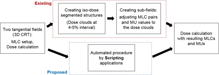
Field-in-field offers numerous benefits in breast cancer radiotherapy, but it requires some manual interruptions in the planning procedure. Many treatment planning systems (TPSs), such as Eclipse, Pinnacle, and RayStation, provide a toolkit, called a scripting application programming interface (API), mainly consisting of programming functions. They are designed for user interaction with the TPS such that the users can perform what they try to implement.18-20 However, the toolkit does not support all functions that users desire to attempt. In this situation, incorporating a user-generated program in Windows or Linux into the basic functions provided by the scripting API potentially enlarges the clinical availability. This work presents a combination of the scripting API with a user-executed program for automated FIF treatment planning in breast cancer radiotherapy. The scripting API enables automatic file import and export and provides an interface that the user-executed program can run. The user-generated file (.exe format) created by MATLAB programming conducts the necessary steps of segmenting the dose and projecting the dose clouds and MLC/MU adjustments, as designed. Finally, the combined framework is operated throughout a single code created by the scripting application on the TPS. This work aims to enhance the time efficiency in breast FIF treatment planning without compromising the plan quality, compared to the manual FIF treatment plan. The flowchart in Figure 1 illustrates the intention of this work; it replaces the most time-consuming part in the conventional FIF planning with an automated procedure based on a combination of the scripting application and user-executed programming. The subsequent sections specify the technical considerations of the automated process.
Figure 1.
Comparison between conventional and (proposed) scripting-based field-in-field (FIF) planning schemes. The proposed approach attempts to replace the most time-consuming part in FIF planning with an aid to scripting applications.
Methods
Automated FIF Framework
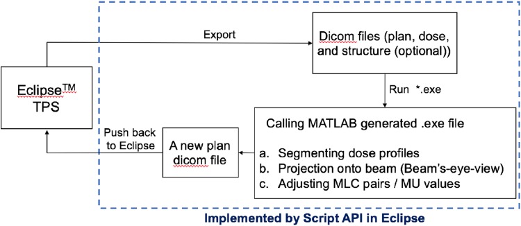
Figure 2 shows the proposed framework of the automated FIF treatment plan. In brief, the scripting program creates a path between the Eclipse TPS server and the local computer, as well as providing the environment in which the executable file (.exe) runs. The executable file that performs user-defined tasks can be programmed by available software, which was created using MATLAB in this work. The platform needs some prerequisites to be implemented. On the TPS, a plan dicom file with 2 tangential fields and a dose dicom file from the beam setting are required before running the executable file. The structure dicom file contains iso-dose surfaces on the dose distribution, corresponding to the specific dose values from 100% to 120% of the prescribed dose at 4% to 5% increments. The structure dicom file is not mandatory, because it can be acquired by the proposed framework.
Figure 2.
Framework for automated breast field-in-field (FIF) with the scripting applications. It first requires dicom files from 2 tangential open fields, which are passed to the MATLAB-executed program that finally results in the subfields with adjusted multi-leaf collimator (MLC) and uniform monitor unit (MU) weights.
Once the dicom files are ready, the scripting API program automatically exports the dicom files from the TPS server to a designated folder. With the exported dicom files, the MATLAB executable program conducts the following tasks: (1) segment the dose distribution by certain iso-dose values, yielding the dose clouds; (2) project the segmented dose clouds onto 2D beam coordinates; and (3) adjust MLC pairs to the projected dose clouds, and determine the subfield weights (MU).
As explained previously, the first step, segmenting the iso-dose line, does not have to be performed if the structure dicom file for the dose clouds were created on the TPS in advance. Without any segmented dose structure information given, the executed program segments the dose distribution by a series of dose values, from approximately the maximum dose of the given distribution to approximately 100% of the prescribed dose at 4% to 5% constant intervals. The structure of the segmented dose clouds is then projected onto the incident beam angle with the pre-determined field boundary, which is also called the beam’s-eye-view (BEV) from the beam perspective. The main task of this framework, thus, is to adapt MLC pairs to the segmented dose clouds, which encourages dose homogeneity inside the target volume. The weights of the subfields were uniformly set up to be approximately 4 MUs each, which is 3% to 4% of the beam weights of the open fields, depending on the given beam weights and entire number of subfields in each beam direction. As a result, the open field contributes to approximately 78% to 82% of the entire beam weight. The detailed weights for the subfields are automatically adjusted in the dose calculating procedure of TPS. The information regarding MLC pairs and weights of the subfields is saved in a new plan dicom file that is pushed back to Eclipse RTP program for dose calculations.
Technical Considerations
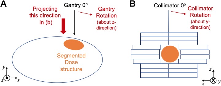
As described in Figure 3, the gantry and collimator rotate about the z- and y- directions, respectively, in the treatment machine. On the Eclipse TPS, the gantry and collimator rotations are represented by the clockwise direction; they are considered counter-clockwise from the beam perspective. In addition, the transverse (x) and longitudinal (y) directions on the 2-D beam coordinate system in Figure 3B correspond to the x- and z-axes in 3-D image space. These 2 facts are important in adjusting MLC pairs of subfields to the segmented dose clouds. A point on the structure contour saved in the dicom file is transformed into 2-D beam coordinates by
| 1 |
where x, y, and z are the coordinates of contours in mm for the segmented dose clouds in 3-D image space, and x rot, y rot, and z rot are the rotated coordinates after gantry (θ g) and collimator (θ c) rotations for the beam projection. BEVx,y are the 2-D projected coordinates, which are used to determine the MLC leaf position in the end.
Figure 3.
Consideration of (A) gantry and (B) collimator rotations in 3-D image space and 2-D beam coordinates. The 2-D beam coordinate system finally interprets y- and z-directional components in 3-D image space to the transverse (x) and longitudinal (y) directions.
Furthermore, the executed program takes the MLC physical constraints into account. It was designed for the MLC pairs on each side to be distant within 15 cm. Once exceeding this limit, the lagging MLC pairs are operated to follow the leading MLC pairs to remain less than 15 cm away. This constraint was required in one of our retrospective test cases, where the patient was in a prone position. It enhances the working efficiency by preventing the dosimetrists from further adjusting MLC pairs in this situation. In addition, the segmented iso-dose surface could lead to separated islands. Under the presence of the isolated dose clouds in projecting onto the 2-D beam space, the executed program automatically creates one or more extra subfields to encourage dose uniformity inside the target volume, as is done by the manual FIF procedure. The executed program takes care of the segmented dose clouds placed in each side. If the isolated cloud is located and projected onto the lateral side, the MLC pairs in the medial side do not block the cloud for the FIF plan. Although the range of the dose cloud projection for MLC adjustment could be changed by the user-defined value, it was set to be the mid-line between 2 tangential fields in this work.
Evaluation
To validate the proposed framework, this study tested 40 retrospective breast cancer patient cases, treated by the FIF technique in our institute. The cases consisted of 38 and 2 patients treated in supine and prone positions, respectively. As stated previously, the manual FIF plans were composed of 4 to 8 subfields, including extra subfields to process the isolated segmented dose clouds. The values for dose segmentation ranged from approximately (D max−2) Gy to approximately 94% to 98% of the prescribed dose at the constant interval. Once the maximum dose of the open field plan did not exceed 120% of the prescribed dose, the interval was set to be 4%. When exceeding 120%, the interval between dose clouds was defined as 5% to maintain a similar number of subfields. The lower bound for the subfield was determined by the distance between 2 opposing MLC pairs for blocking the specific dose cloud. The details of determining MUs in our proposed framework were the same as the manual FIF planning in our institute to prevent the automated plan from being deviated. The MU weights of open fields took approximately 80% of all the MUs for each tangential field, and each subfield was assumed to have 4 MUs before normalization.
The automated framework referred to the identical dose distribution obtained from 2 open tangential fields set to the manual FIF plan in each case. All patients employed in the analysis were early stage breast cancer, and they received whole breast irradiation without regional nodal irradiation. The standard tangential field for whole breast irradiation was determined according to the NRG Oncology/NSAPB B-51/RTOG 1304 protocol.21 The target volume was set to V 100% of the initial plan in most cases, and was replaced by V 102% in the absence of 100% volume. For comparison, the automatic FIF plan needed to be normalized for the mean of target volume to be analogous to that in the manual FIF plan. Throughout the automated procedure, the number of subfields was changed in some cases because the proposed framework may be different in defining the extra subfields for the isolated segmented dose clouds. However, it did not add or subtract the insufficient/surplus subfields for fair comparison. This study pursued enhancement of the planning efficiency throughout the automated process with an aid to the scripting API and user-executed programming, which was quantified by the planning time, compared to that of the manual planning process. In addition, because it focused on preserving the plan quality, this study tried to investigate the dosimetric effect from the automation on the 4 structures: target volume (>100/102% of the prescribed dose), whole-breast region, one side of the lung adjacent to the target volume, and heart, relative to the FIF plan manually done. In addition, it analyzed the homogeneity inside the planning target volume (PTV) for the 2 resulting plans; the homogeneity is defined as the ratio of maximum dose to minimum dose inside the target volume for each plan. A statistical analysis by the paired t test assuming a normal distribution was performed using IBM SPSS Statistics (version 21).
Results
The proposed automatic planning scheme was designed to improve the planning efficiency in breast FIF treatment planning. With the radiation treatment dose and plan dicom files provided, it took less than 1 min for the MATLAB-executed program to yield the subfields with adjusted MLC and MU weights, to push back to the TPS, and to reload the resulting plan. Table 1 compares the time elapsed for planning in the manual and automated procedures. Depending on the planner’s experience, the time elapsed for manual FIF planning would be variable, which resulted in 30 to 40 minutes elapsed on average. On the contrary, total planning time in the proposed scheme was reduced to less than 50%, relative to the conventional breast FIF planning, where the benefit in time stemmed from the automated MLC and MU adjustment throughout the scripting application. Even with the further adjustment needed to slightly modify the MLC shape to the dose clouds and MU weights, the total planning time remained less than 15 minutes on average.
Table 1.
Comparison in Time Elapsed for Breast FIF Planning Throughout the Manual and Automated Procedures.
| MLC/MU Adjustment | Total Planning Time | |||
|---|---|---|---|---|
| Manual | Automated | Manual | Automated | |
| Time elapsed (min.) | >20 | <1 | 30-40 | 10-15 |
Abbreviation: MLC, multi-leaf collimator; MU, monitor unit.
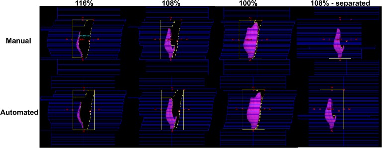
Figure 4 shows MLC pairs adjusted to some segmented dose clouds (116%, 108%, and 100% iso-dose lines) by the automated procedure in one of the 40 test cases, against the manual FIF plan. This example led to one extra subfield to fill out the empty space derived from the 108% iso-dose surface. The resulting MLC pairs from the automated procedure were demonstrated to be similar to those manually performed. In most cases of our tests, the MLC pairs kept track of the segmented dose structures well, like the manual FIF. Multi-leaf collimator pairs in some cases were placed in different ways than the manual ones because of the additional subfield corresponding to the isolated dose cloud.
Figure 4.
Comparison of multi-leaf collimator (MLC) pairs between the manual and automated field-in-field (FIF) plans for one of the retrospective patient cases (structures in purple are corresponding to the dose clouds that represent 116%, 108%, 100% of the iso-dose lines from the 2 open tangential plans).
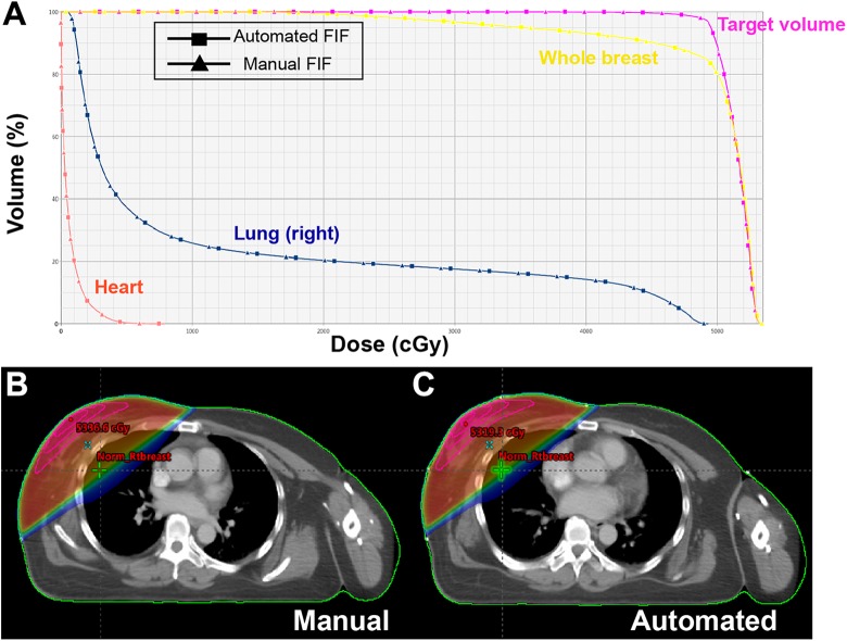
Figure 5 illustrates the dose volume histograms of the 4 structures and dose distributions of the automated and manual FIF plans. In Figure 4A, the solid lines with square and triangle markers represent the automated and manual FIF plans, respectively, where they are quite analogous to each other. Figures 4B and C visualize the dose distributions obtained from the manual and automated processes, where the dose window level ranged from 10% to 106% of the prescribed dose for both. It turned out that both resulting plans behaved similar to each other in dose distribution, although the maximum dose value from the automated process is slightly higher than that from the manual.
Figure 5.
Comparison between manual and automated breast field-in-field (FIF) plans in (A) DVHS (target volume in purple, whole breast in yellow, lung [right] in blue, and heart in red), and (B and C) dose distributions for one of the test cases.
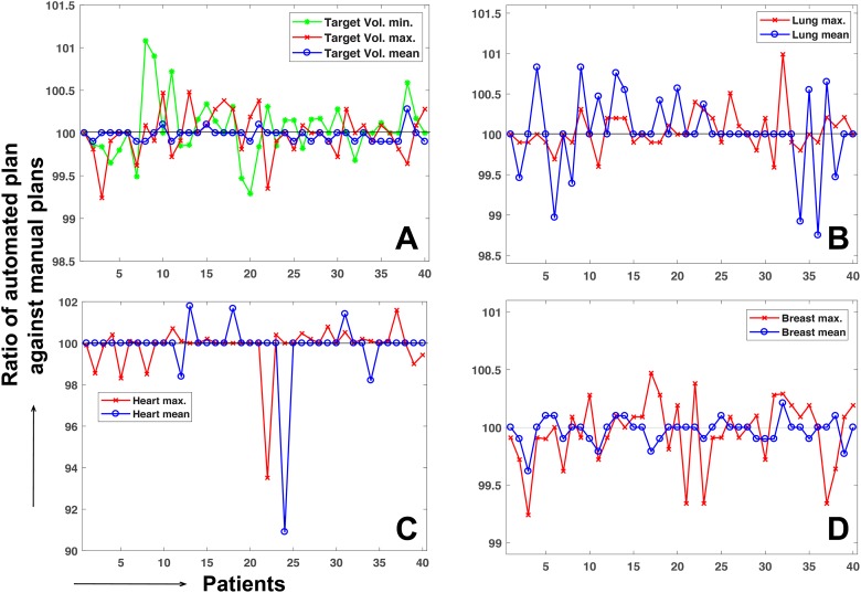
Figure 6 shows a numerical comparison between the manual and automated plans in dosimetric effect for the 40 retrospective breast FIF patient cases. The dose delivered to the target and critical structures vary from patient to patient depending on the tumor location. Thus, the automated plan was normalized, such that the norm points of both the plans have the same dose value. Then, the ratio was measured of the maximum (minimum only for target volume) and mean dose of the structures obtained from the automated plans to those of the manual plans. In most cases, the maximum and mean dose values of the target and critical structures from the automated procedure differed from those of manual plans by less than 1%, except for the heart. The difference by approximately 5% to 10% between the manual and automated plans in the heart was due to a too-low dose irradiated to the heart in the case of the breast cancer placed in the right-hand side, for example, 1.1% and 1.0% mean dose of the prescribed dose in the first case from manual and automated procedures. The difference was identified to be mainly due to the process of selecting the extra subfield for the isolated island in a side of tangential fields.
Figure 6.
Ratio of the mean, maximum, and minimum (target volume only) dose value from the automated procedure against those values from the manual procedure for (A) target volume, (B) lung, (C) heart, and (D) whole breast.
Table 2 lists the mean and standard deviation of the dosimetric data shown in Figure 5, including the ratio of the automated plan to the manual plans and statistical analysis with P value. The mean values of the ratio between the 2 plans were approximately 100% for different categories with less than 1% standard deviation, except for the standard deviation of the heart. Table 2 also includes the information of the homogeneity index (HI; defined as the ratio of PTV max. relative to the PTV min. in this work) between the 2 plans. It shows that the automated plan tends to successfully retain HI, compared to the manual plan, which implies that the dose behavior in the target volume from the automated process is well maintained. Of note, the P values ranged from 0.1 to 0.7, indicating no statistically significant difference between the treatment planning metrics between the automated and manual FIF methods.
Table 2.
Dosimetric Information, Mean, and Standard Deviation of the Ratio of the Automated Field-in-field (FIF) Plans to the Manual Breast FIF Plans Over the 4 Different Structures, and P Value Measurement.
| Manual Plan | Automated Plan | Automated Plan/Manual Plan | P Value | |
|---|---|---|---|---|
| PTVmin | 63.71 (10.63) | 63.74 (10.66) | 100.05 (0.35)% | .305 |
| PTVmax | 105.86 (0.96) | 105.84 (0.94) | 99.99 (0.27)% | .486 |
| PTVmean | 102.55 (0.83) | 102.53 (0.88) | 99.98 (0.08)% | .118 |
| HI | 1.71 (0.33) | 1.71 (0.33) | 99.94 (0.46)% | .440 |
| Lungmax | 95.07 (15.60) | 95.10 (15.58) | 100.04 (0.25)% | .326 |
| Lungmean | 14.28 (5.80) | 14.29 (5.82) | 100.02 (0.47)% | .323 |
| Heartmax | 43.73 (44.21) | 43.79 (44.32) | 99.82 (1.18)% | .090 |
| Heartmean | 2.44 (2.22) | 2.43 (2.23) | 99.50 (2.49)% | .711 |
| Breastmax | 105.78 (0.92) | 105.74 (0.88) | 99.96 (0.29)% | .330 |
| Breastmean | 96.70 (3.85) | 96.67 (3.90) | 99.97 (0.11)% | .115 |
Abbreviation: HI, homogeneity index.
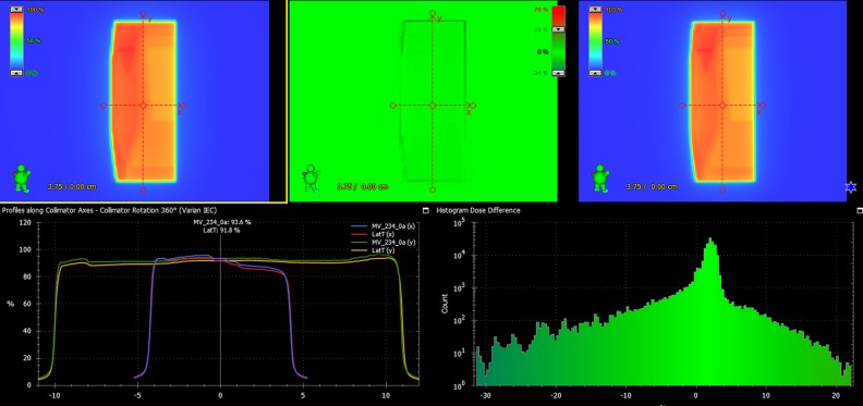
To ensure the dosimetric safety, IMRT quality assurance (QA) by portal dosimetry was performed for 10 patients randomly chosen from the patient cohort. As a result, the measured results were different from the plans by 1.15% in the mean dose difference (0.54%-1.84%) of the maximum predicted dose, and 99.48% of γ passing rate with 3%/3 mm criterion on average. Figure 7 shows the QA result of one of the 10 cases, which shows 1.28% absolute dose difference, and 100% γ passing rate with 3 mm/3% criterion. It demonstrates that the plan produced from the automated framework is clinically safe to be delivered.
Figure 7.
Portal dosimetry result of the automated field-in-field (FIF) plan for one of the 10 selected patients.
Discussion
The FIF plan is the forward step-and-shoot IMRT technique, which was intended to encourage dose homogeneity inside the target volume. It is characterized by adding subfields to the open fields, which block the dose clouds segmented by the designated dose values for dose uniformity. Despite the dosimetric benefits, the planning procedure has been considered inefficient because of accompanying manual interventions in segmenting the dose clouds, and adjusting mainly MLC and MU parameters. The proposed framework promotes automation in the FIF planning process to enhance the planning efficiency with an aid to the Eclipse Scripting API, enabling the user to interact with TPS to perform some tasks. On the basis of the available scripting API, this work presents an automated FIF treatment planning framework: (1) importing/exporting dicom files and providing an interface for the user-executed programming by the scripting application, and (2) an automated FIF planning procedure conducted by a MATLAB-generated execution file. A couple of studies22,23 have been conducted for the automated breast planning in the context of 3-D CRT and IMRT. This work could be differentiated from the previous works in the sense that all tasks are finally performed with one scripting code and a one-click option on the TPS with each patient data set loaded.
It is conceivable that the inverse planning for breast IMRT could be the other option, given that the FIF planning procedure is relatively inefficient. In fact, however, the forward FIF planning is beneficial relative to the inverse planning because FIF planning is straightforward to figure out how to deliver the dose to the target volume based upon the region of high dose irradiation. Also, it saves the total MUs, and normal tissue volume that receives the low dose of radiation, compared to the IMRT inverse planning. With respect to the plan quality, we had an observation to be discussed, as described in Figure 8. The automated FIF plan with 5 to 6 segments per each beam outperforms the inverse planning-based breast IMRT with the same number of segments, while the inverse planning guarantees the similar homogeneity (uniformity) in target volume with 15 to 20 segments. Thus, considering the benefits from the forward FIF planning, this study focused on founding an automated workflow employing the Scripting applications that enhances the breast FIF planning efficiency. It is true that the 2 tangential beam configuration is limited in improving the dose conformity to the target volume, and dose sparing to certain organs. According to the clinical protocol in our institution, the breast IMRT with 7 to 10 static fields is then considered for the patients under such conditions.
Figure 8.
Comparison of the PTV dose-volume histogram and homogeneity index (HI) between forward field-in-field (FIF) plan (6 segments for each tangential field) and inverse planning-based IMRT plans with (A) 6 segments, (B) 10 segments, and (C) 15 segments.
An automated FIF framework could achieve even better efficiency in the planning process. The time elapsed for the steps described above was approximately 30 to 35 seconds, which reduced the time taken for the manual MLC and MU adjustments. The total planning time including the 2 open-field creation steps and final dose calculation took approximately 10 to 15 minutes, which reduced the planning time by more than 50% relative to the manual plans. The preceding section describes how enhanced efficiency by the automated process affects the dosimetric aspects in the resulting plan. We tested the automated framework for the 40 retrospective breast cancer data sets with plans manually performed by measuring the mean and maximum dose of the automated FIF plans, HI, and V pres of the target volume (100% or 102% iso-dose line) after normalizing it to the mean dose of the target volume in the manual plan for each case. The mean and maximum dose values did not exceed 1% relative to those of the manual plans in most cases. The mean of the ratio ranged from 99.8% to 100.1%, and the standard deviation was no greater than 0.5%, except for the heart. The automated plan tended to have slightly greater target dose coverage (quantified by V pres), while resulting in slightly worse dose homogeneity inside the target volume instead. However, the dosimetric difference was demonstrated to be statistically negligible, because the P values for all evaluating criteria ranged from 0.1 to 0.7 from the 40-sample size. The dosimetric difference between the manual and automated plans was frequently caused by placement of a few leaves on the subfields, and the selection of a subfield regarding the isolated dose cloud. In a few cases, it was also derived from selecting or neglecting the isolated dose clouds. As stated in the preceding section, the selection of extra subfields could be managed by a user-defined value that changes the depth of projection onto the MLC leaf positions in the MATLAB-executed program.
This work promoted the automated framework in breast FIF planning, combining the scripting application interface with a user-executed program. In past decades, some vendors, including Eclipse (Varian Medical Systems, Palo Alto, USA), Pinnacle (Philips Healthcare, Eindhoven, Netherlands) and RayStation (RaySearch Laboratories, Stockholm, Sweden), have developed and distributed scripting programming to help achieve automated procedures in tasks associated with radiation oncology. However, the API toolkit does not assure whole coverage and freedom to users for several reasons, mostly because of safety issues. Contrarily, programming in Windows or Linux is capable of eliminating the constraints in implementation. We attempted to formulate the framework by integrating the benefits of both the scripting API and Windows-based programming, which could broaden the application of the scripting API in clinical workflow.
Obviously, this automated FIF framework could be employed in planning the other body sites, such as whole brain or total-body irradiation. In addition, the proposed workflow that combines Scripting with user-executed programming could be applied to clinical purposes other than the planning process once proved efficient and safe. Importantly, however, modification of clinical dicom files should be conducted in observance of clinical protocols. It may be required to consult with oncologists and manufacturers about its adequacy before applying this approach to clinical applications. In our institution, the proposed platform has been used to plan the patients with breast cancer for about half a year, which currently create 30 FIF planning cases per week on average. Before its clinical use, we have passed through consulting with a group of radiation oncologists, medical physicists and dosimetrists, and set-up on the regular check-up procedure for the planning parameters produced from the proposed workflow. There exists a certain QA system24 that could facilitate this process potentially, which could be also employed in this clinical workflow.
Conclusion
Our automated FIF procedure was developed to promote the planning efficiency in breast FIF planning by combining Eclipse Scripting applications with a MATLAB executable program. For validation, we tested 40 retrospective breast FIF plan cases and compared the automated and manual FIF plans. Even with a significant reduction in elapsed time for the planning process, it was demonstrated that the automated plans deviated by less than 1% in mean and maximum dose values and target volume coverage against the manual plans. The proposed type of scripting program application, combining the script and the executable program, would be able to increase the efficiency in other potential clinical tasks in radiation oncology.
Acknowledgments
We thank the anonymous reviewers whose insightful comments and suggestions helped improve and clarify this manuscript.
Abbreviations
- APIs
application programming interfaces
- BEV
beam’s-eye-view
- CRT
conformal radiation therapy
- ESAPI
eclipse application programming interface
- FIF
field-in-field
- HI
homogeneity index
- IMRT
intensity modulated radiation therapy
- MLC
multi-leaf collimator
- MU
monitor unit
- TBI
total-body irradiation
- TPS
treatment planning system.
Authors’ Note: This study was approved by the Institutional Review Board of Asan Medical Center (2018-1221), and informed consent was waived because of the retrospective nature of the study.
Declaration of Conflicting Interests: The author(s) declared no potential conflicts of interest with respect to the research, authorship, and/or publication of this article.
Funding: The author(s) disclosed receipt of the following financial support for the research, authorship, and/or publication of this article: This work was supported by a National Research Foundation of Korea grant funded by the Korean government (NRF-2013M2A2A7043506).
ORCID iD: Hojin Kim, PhD  https://orcid.org/0000-0002-4652-8682
Byungchul Cho, PhD  https://orcid.org/0000-0003-3871-7114
References
- 1. Van Asselen B, Raaijmakers CP, Hofman P, Lagendijk JJ. An improved breast irradiation technique using three-dimensional geometrical information and intensity modulation. Radiother Oncol. 2001;58(3):341–347. [DOI] [PubMed] [Google Scholar]
- 2. Brewster L, Mohan R, Mageras G, Burman C, Leibel S, Fuks Z. Three dimensional conformal treatment planning with multileaf collimators. Int J Radiat Oncol Biol Phys. 1995;33(5):1081–1089. [DOI] [PubMed] [Google Scholar]
- 3. Vicini FA, Sharpe M, Kestin L, et al. Optimizing breast cancer treatment efficacy with intensity-modulated radiotherapy. Int J Radiat Oncol Biol Phys. 2002;54(5):1336–1344. [DOI] [PubMed] [Google Scholar]
- 4. Harsolia A, Kestin L, Grills I, et al. Intensity-modulated radiotherapy results in significant decrease in clinical toxicities compared with conventional wedge-based breast radiotherapy. Int J Radiat Oncol Biol Phys. 2002;68(5):1375–1380. [DOI] [PubMed] [Google Scholar]
- 5. Donovan E, Bleakley N, Denholm E, et al. Randomized trial of standard 2D radiotherapy (RT) versus intensity modulated radiotherapy (IMRT) in patients prescribed breast radiotherapy. Radiother Oncol. 2007;82(3):254–264. [DOI] [PubMed] [Google Scholar]
- 6. Pignol JP, Olivotto I, Rakovitch E, et al. A multicenter randomized trial of breast intensity modulated radiation therapy to reduce acute radiation dermatitis. J Clin Oncol. 2008;26(13):2085–2092. [DOI] [PubMed] [Google Scholar]
- 7. Bentzen SM, Agrawal RK, Aird EG, et al. The UK Standardisation of Breast Radiotherapy (START) Trial A of radiotherapy hypofractionation for treatment of early breast cancer: a randomised trial. Lancet Oncol. 2008;9(4):331–341. [DOI] [PMC free article] [PubMed] [Google Scholar]
- 8. Leavitt DD, Martin M, Moeller JH, Lee WL. Dynamic wedge field techniques through computer-controlled collimator motion and dose delivery. Med Phys. 1990;17(1):87–91. [DOI] [PubMed] [Google Scholar]
- 9. Klein EE, Low DA, Meigooni AS, Purdy JA. Dosimetry and clinical implementation of dynamic wedge. Int J Radiat Oncol Biol Phys. 1995;31(3):583–592. [DOI] [PubMed] [Google Scholar]
- 10. Leavitt DD, Klein E. Dosimetry measurement tools for commissioning enhanced dynamic wedge. Med Dosim. 1997;22(3):171–176. [DOI] [PubMed] [Google Scholar]
- 11. Gibbons JP. Calculation of enhanced dynamic wedge factors for symmetric and asymmetric photon fields. Med Phys. 1998;25(8):1411–1418. [DOI] [PubMed] [Google Scholar]
- 12. Zhu J. Generation of wedge-shaped dose distributions through dynamic multileaf collimator dose delivery. J Appl Clin Med Phys. 2005;6(3):37–45. [DOI] [PMC free article] [PubMed] [Google Scholar]
- 13. Mayo C, Lo YC, Fitzgerald TJ, Urie M. Forwardplanned, multiple-segment, tangential fields with concomitant boost in the treatment of breast cancer. Med Dosim. 2004;29(4):265–270. [DOI] [PubMed] [Google Scholar]
- 14. De la Torre N, Figueroa CT, Martinez K, Riley S, Chapman J. A comparative study of surface dose and dose distribution for intact breast following irradiation with fieldin-field technique vs. the use of conventional wedges. Med Dosim. 2004;29(2):109–114. [DOI] [PubMed] [Google Scholar]
- 15. Borghero YO, Salehpour M, McNeese MD, et al. Multileaf field-in-field forward-planned intensity modulated dose compensation for whole-breast irradiation is associated with reduced contralateral breast dose: a phantom model comparison. Radiother Oncol. 2007;82(3):324–328. [DOI] [PubMed] [Google Scholar]
- 16. Prabhakar R, Julka PK, Rath GK. Can field-in-field technique replace wedge filter in radiotherapy treatment planning: a comparative analysis in various treatment sites. Australia Phys Eng Sci Med. 2008;31:317–324. [DOI] [PubMed] [Google Scholar]
- 17. Morganti AG, Cilla S, de Gaetano A, et al. Forward planned intensity modulated radiotherapy (IMRT) for whole breast postoperative radiotherapy. Is it useful? When? J Appl Clin Med Phys. 2011;12(2):213–222. [DOI] [PMC free article] [PubMed] [Google Scholar]
- 18. Xhaferllari I, Wong E, Bzdusek K, Lock M, Chen J. Automated IMRT planning with regional optimization using planning scripts. J Appl Clin Med Phys. 2013;14(1):4052. [DOI] [PMC free article] [PubMed] [Google Scholar]
- 19. Wu Q, Djajaputra D, Liu HH, Dong L, Mohan R, Wu Y. Dose sculpting with generalized equivalent uniform dose. Med Phys. 2005;32(5):1387–1396. [DOI] [PubMed] [Google Scholar]
- 20. Wang H, Xing L. Application programming in C# environment with recorded user software interactions and its application in autopilot of VMAT/IMRT treatment planning. J Appl Clin Med Phys. 2016;17:189–203. [DOI] [PMC free article] [PubMed] [Google Scholar]
- 21. Mamounas EP, White JR, Bandos H, et al. NSABP B-51/RTOG 1304: Randomized phase III clinical trial evaluating the role of postmastectomy chest wall and regional nodal XRT (CWRNRT) and post-lumpectomy RNRT in patients (pts) with documented positive axillary (Ax) nodes before neoadjuvant chemotherapy (NC) who convert to pathologically negative Ax nodes after NC. J Clin Oncol. 2014;32(suppl 15): Abstract TPS1141. [Google Scholar]
- 22. Chen GP, Ahunbay E, Li XA. Automated computer optimization for 3D treatment planning of breast irradiation. Med Phys. 2008;35(6):2253–2258. [DOI] [PubMed] [Google Scholar]
- 23. Ahunbay EE, Chen GP, Thatcher S, et al. Direct aperture optimization-based intensity-modulated radiotherapy for whole breast irradiation. Int J Radiat Oncol Biol Phys. 2007;67(4):1248–1258. [DOI] [PubMed] [Google Scholar]
- 24. Chen GP, Ahunbay E, Li XA. Technical note: development and performance of a software tool for quality assurance of online replanning with a conventional linac or MR-linac. Med Phys. 2016;43(4):1713–1719. [DOI] [PubMed] [Google Scholar]


