Abstract
We described the synthesis and characterization of a new class of bimetallic nanotubes based on Pd/Fe and demonstrated their efficacy in the dechlorination of PCB 77, a polychlorinated biphenyl. Onedimensional iron metal nanotubes of different diameters were prepared by electroless deposition within the pores of PVP-coated polycarbonate membranes using a simple technique under ambient conditions. The longitudinal nucleation of the nanotubes along the pore walls was achieved by mounting the PC membrane between two halves of a U-shape reaction tube. The composition, morphology, and structure of the Pd/Fe nanotubes were characterized by transmission electron microscopy, scanning electron microscopy, inductively coupled plasma-atomic emission spectroscopy, and X-ray powder diffraction spectroscopy. The as-prepared Pd/Fe bimetallic nanotubes were used in dechlorination of 3,3′,4,4′-tetrachlorobiphenyl (PCB 77). In comparison with Pd/Fe nanoparticles, the Pd/Fe nanotubes demonstrated higher efficiency and faster dechlorination of the PCB.
Introduction
Nanomaterials have been used extensively over the last two decades in biosensors, fuel cells, photonics, electronics, and catalysis,1–6 because of their distinct difference in physical and chemical properties from bulk materials.7–10 Because of the tendency of nanoparticles to aggregate, the particles are usually produced in the presence of dispersing agents that introduce surface functionalities (e.g., carboxylates) or are immobilized within polymer matrices.11–14 The unique catalytic properties of the nanoscale materials are attributed to their high surface-to-volume ratio15,16 and the chemical valence unsaturation of the surface atoms,17 which enable binding of reactants. Furthermore, the electronic effects of the almost filled d-shell of group 11 and 12 transition metals make the corresponding nanoparticles efficient catalysts in many reactions.18–20 Specifically, palladium nanoparticles have received much attention not only because of their high catalytic activity, which is similar to platinum,21–23 but also because they are cost-effective in comparison to platinum.24,25 Palladium nanoparticles have been used for several reactions such as hydrogenation, dechlorination, oxidation, Suzuki coupling, and Heck cross-coupling reactions.18,26–30 Interestingly, palladium nanoparticles could form core/shell bimetallic nanoparticles with silver, gold, platinum, and iron.31–36
Pd/Fe bimetallic nanoparticles have been an effective technology in dechlorination reactions involving chlorinated organic hydrocarbons,36–40 in which the Fe core of the nanoparticles reacts (in the aqueous phase) with water to produce hydrogen. This hydrogen along with the chlorohydrocarbon adsorbs on the surface of the palladium nanoparticles, which facilitate the dechlorination reaction. The smaller the size of Pd/Fe nanoparticles, the higher the reactivity and catalytic surface area per unit mass. However, owing to the high reactivity of the Fe nanoparticles and their ferromagnetic properties, Fe nanoparticles tend to aggregate during preparation.41 There is also evidence of aggregation during the palladization step.14 In addition, it has been recognized that these particles aggregate during remediation and adhere to the soil.39 Consequently, the surface-to-volume ratio of the particles is decreased, which impacts the rate of the dechlorination reaction. This presents a major challenge for investigators to stabilize the dispersed form of the Pd/Fe nanoparticles. Several surfactants have been used to stabilize the nanoparticles including poly(acrylic acid),11 starch,42 cetyltrimethyl-ammonium bromide,43 carboxylmethylcellulose,13 and Triton X-100.44 In another approach, the aggregation of the particles is prevented by in situ synthesis of nanoparticles in porous support such as a polyacrylic acid/polyethersulfone composite membrane,45 and a poly(vinylidene fluoride) microfiltration membrane.12
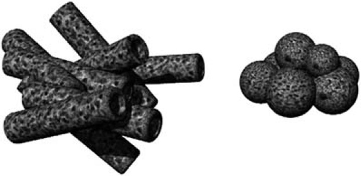
In recent years,16,46–51 attention has been devoted to the nanotube architecture because of several superior properties. For instance, the hollow interior of nanotubes provides a high ratio of surface-to-core atoms,52 which enhances surface-dependent characteristics such as surface plasmon resonance,53 conductivity,54 reactivity and catalytic ability.55 Moreover, metal nanotubes are of special interest because of the quantum confinement along the tube and the excess charge density on the interior wall.56,57 The nanotube structure exhibits higher exposed surface area to mass ratio than nanoparticles, even when aggregates are formed; this is because the internal nanoparticles in an aggregate have their surface covered by the next layer of particles, whereas aggregates of nanotubes tend to stack in a fashion similar to the “Mikado game” pieces. Although contact is made among the nanotubes, the majority of the surface is unobstructed (Chart 1). All these interesting characteristics make the Pd/Fe nanotubes a potential route to increase the efficiency of the environmentally important dechlorination reactions.
Chart 1.
Schematic diagram indicating the higher exposed surface area of nanotube aggregates as compared to nanoparticle aggregates.
Two general approaches have been followed for the synthesis of metallic nanotubes. The template-free methods include hydrothermal synthesis, surfactant-assisted solvothermal synthesis, polyol, and electrodeposition from ionic liquid.58–61 The template-based method, popularized by Martin’s group,62,63 is the most successful and generic approach for the preparation of 1-D nanostructures with hollow interior. In this approach a nanoporous membrane is utilized for nucleation of 1-D nanoscale materials inside the membrane pores. This is followed by wet etching or calcination of the membrane in order to liberate the nanotubes. The preparation of the nanotubes inside the membrane pores is achieved by several methods including electrochemical deposition, electroless deposition, polymer-assisted deposition, sol–gel deposition, and chemical vapor deposition (CVD).52,64–69 Most of these methods required pre-functionalization of the membrane pores to allow for the nucleation of the 1-D nanotubes. Alternatively, a simple approach of the conventional template-based method has been introduced.70–72 In this approach, the template is placed between two compartments of a U-shape reaction tube in a way that separates two different electrolyte solutions. This design allows for the diffusion of the electrolytes inside the membrane pores. Consequently, a local reaction results in the deposition of the nanomaterials on the pore-walls.
To date, several metallic nanotubes have been prepared, such as those of Au, Pd, Ni, Zn, Ag, Pt, and Pb.73–78 However, the preparation of zero-valent iron (ZVI) nanotubes remains a challenge because of the high reactivity of iron metal nanostructures in the aqueous chemical etching processes of the membrane template or the oxidation to iron oxides during template calcinations. Indeed, few reports have described the synthesis of Fe nanotubes. In most of these reports, electrodeposition is used to grow the Fe nanotubes in the nanopores of polycarbonate (PC)79–81 or anodized alumina membranes (AAM).80,82–84 However, it was difficult under this approach to prevent the oxidation of the Fe metal nanotubes to iron oxide nanotubes, which could not be used for hydrogenation or dechlorination reactions. We describe here the synthesis and characterization of a new class of bimetallic nanotubes based on Pd/Fe (Pd is post-coated of Fe nanotubes) using a modified-template based method. The efficacy of the as-prepared Pd/Fe nanotubes toward PCB dechlorination is also demonstrated.
Experimental
1. Synthesis of palladium/iron (Pd/Fe) nanoparticles
The Pd/Fe nanoparticles were prepared according to the procedure published elsewhere36–40 with some modifications. Briefly, the reaction was carried out in a 500 mL three-neck round bottom flask, where a solution of 0.1 M FeSO4 stabilized with 0.5 M ascorbic acid was added. A fast stream of argon was injected from one neck, which is used for degassing and stirring the reaction mixture and a vacuum was applied on the other neck. A solution of 0.2 M NaBH4 was injected from the vertical neck using a peristaltic pump at a rate of 0.1 mL s−1. The addition of sodium borohydride was stopped when the reaction mixture turned black and bubbles ceased to evaporate. A strong magnet was used to collect the as-prepared Fe nanoparticles to the bottom of the flask, while the solution was decanted. The last step was repeated three times for washing with oxygen-free water and two times with ethanol. A shell of palladium nanoparticles was deposited on the surface of the iron nanoparticles by soaking the freshly prepared iron nanoparticles in 0.01 wt% ethanolic solution of palladium acetate (Alfa Aesar, Ward Hill, MA 01835) for 2–24 h. At the specified time, the Pd/Fe nanoparticles were separated and washed two times with absolute ethanol using the strong magnet protocol mentioned previously. The as-prepared Pd/Fe nanoparticles were dispersed in ethanol or dried under vacuum for use in dechlorination or further characterizations.
2. Synthesis of (Pd/Fe) nanotubes
Track-etched polycarbonate (PC) nanoporous membranes of 400, 200, and 100 nm pore diameters and 47 mm diameter (Millipore, Billerica, MA 01821) were used as a template for the preparation of the iron nanotubes. These membranes are sold in hydrophilic or hydrophobic form with a thickness of 7–22 μm with 5–20% pore density. In a typical synthesis of one-dimensional Fe0 nanotubes, a PC membrane was mounted between the two compartments of a custom made U-tube cell in a way that the membrane separates two equal volumes of electrolyte solutions (see ESI†, Fig. S1). These two electrolyte solutions were prepared as follows: the oxidant solution was composed of 1 × 10⁻³ M ferrous sulfate stabilized by 1 × 10⁻² M ascorbic acid; the reductant solution was composed of 1 × 10⁻² M sodium borohydride. The U-tube cell was leveled horizontally. The oxidant solution was degassed for 20 min by argon prior to pouring in the U-tube. Both solutions were poured in each half of the U-tube simultaneously. Different reaction spans were investigated for optimum yield of nanotubes. At a specific time, the solutions were poured off the U-tube and the membrane was instantly sonicated for 2 min in oxygen free water to remove the unwanted nanoparticles if any was formed on the membrane surface. Subsequently, the membrane was washed thoroughly with water and ethanol and dried with argon gas. The as-prepared Fe nanotubes were extracted by dissolving the PC membrane in 10 mL methylene chloride and washing two times with methylene chloride and two times with ethanol. Palladium nanoparticles were deposited on the as-prepared Fe nanotube by adding 1 mg of palladium acetate to 10 mL Fe nanotubes colloidal solution. The palladization reaction was run overnight, and the Pd/Fe nanotubes were washed two times with ethanol and dispersed in ethanol.
3. Electron microscopy
A JEOL 2010F field emission electron microscope equipped with an energy-dispersive X-ray detector and running at an accelerating voltage of 200 kV was used for the nanoscale characterization of Pd/Fe nanoparticles, Fe nanotubes and Pd/Fe nanotubes. The size, structure, morphology, and elemental composition were studied using bright field transmission electron microscopy, energy dispersive spectroscopy (EDS), selected area electron diffraction (SAED), and dark field scanning transmission electron microscopy. EDS line profile at STEM mode was used to verify the hollow structure of the nanotube. To obtain this profile a 1 nm in diameter electron probe was scanned transversally across a Fe nanotube and a Fe nanowire while the Fe Kα X-ray was detected at discrete positions along the line with a dwell time of 1 s. EDS-mapping at STEM mode was used to study the distribution and the ensemble of Pd nanoparticles on the as-prepared Fe nanotubes. A 0.5 nm electron probe was used to scan an area of 48 × 40 pixels of the Pd/Fe nanotube with a dwell time of 0.5 s. High-resolution transmission electron microscopy (HRTEM) measurements along with SAED were performed to investigate the crystal structure of the as-prepared Fe and Pd/Fe nanotubes. The TEM samples were prepared by dispersing the as-prepared nanotubes or nanoparticles in ethanol and dropping few drops to a copper grid with a lacy carbon layer. A Hitachi 4300 scanning electron microscope (SEM) was also used for characterization of the morphology of the as-prepared Pd/Fe nanotubes. The sample was prepared by dropping and air drying a small volume of the Pd/Fe ethanol colloidal solution onto a silicon wafer. The silicon wafer was then sputter-coated with thin layer of gold–palladium alloy in order to increase the electrical conductivity of the sample and to prevent charging of the specimen surface during electron irradiation.
4. XRD, BET, and ICP analysis
The purity and crystalline structure of the as-synthesized Fe nanoparticles were studied using a Bruker AXS D8 Discover powder X-ray diffractometer (XRD) operating in Bragg configuration and equipped with a Cu Kα radiation (λ = 1.54056 Å) source. The diffraction patterns were acquired over the range of 2θ 25–90° at a scanning rate of 1° min−1 with a step size of 0.02°. The BET surface area was obtained by N2 adsorption at 77 K using a Quantachrome NOVA 1200 at the University of Florida, Particle Engineering Research Center. A Thermo iCAP 6500 duo ICP-AES system (Thermo Fisher Scientific) was used to determine the metallic composition of the Fe and Pd/Fe nanoparticles and nanotubes. The samples were prepared by dissolving 1 mg of dry Fe and Pd/Fe nanoparticles and nanotubes in 1 mL nitric acid and further diluted to 25 mL.
5. Dechlorination experiment
Batch reactions were conducted to study the reactivity of the as-prepared Pd/Fe nanotubes in dechlorination of 3,3′,4,4′-tetrachlorobiphenyl (PCB 77), a tetrachlorinated PCB congener. These reactions were performed in two different sizes glass vials with PTFE septa caps. For 1 g L−1 Pd/Fe nanoparticles or 0.1 g L−1 Pd/Fe nanotubes metal loading, the reactions were done in a 65 mL glass vial in which 60 mL of 25 μM 50/50 (v/v) ethanol/water solution of PCB 77 was added. The vials were placed on a wrest shaker at maximum speed. All experiments were performed under identical agitation conditions to ensure the absence of bias from external diffusion constrains on the interpretation of the experiments. At specific times, the nanotubes or nanoparticles were collected using a strong magnet, and 1 mL of the solution was withdrawn and transferred to a 2 mL glass vial containing 1 mL hexanes for extraction of the PCBs. Because of the mass confinement of the Pd/Fe nanotubes, the 1 g L−1 metal loading was done in 2 mL glass vials. In this case, at the specific time, the vial was sacrificed for extraction of the PCBs. The extraction vials were set on a shaker overnight to attain extraction equilibrium. A volume of 100 μL of the hexane layer was combined with 10 μL of PCB 209 as internal standard before GC-MS (Agilent, Santa Clara CA 95051) analysis.
Results and discussion
Different diameter Fe nanotubes were synthesized by a simple and cost-effective procedure at ambient conditions. Additionally, this procedure provides control of the size, morphology, and crystal structure of the 1-D nanostructures via altering the pore size of the template and the concentrations of the reactants. Specifically, a track-etched polycarbonate membrane was mounted between two compartments of a custom made U-shape reaction tube. The polycarbonate membrane was chosen instead of other templates, such as porous alumina, because the latter requires etching of the template in harsh aqueous media, which lead to oxidation of the ZVI. The longitudinal nucleation of the nanotubes along the pore walls was achieved by the localized electroless reduction of ferrous sulfate, stabilized by ascorbic acid, placed in one side of the U-tube cell, upon diffusion of sodium borohydride from the other side of the cell. Different mechanisms have been proposed to describe the growth of 1-D nanostructures leading to solid nanowires or hollow nanotubes based on the concentration of the reactants, the interactions between the template pores and reagents, and the reaction duration and conditions.72,85,86 On the account of these mechanisms, the concentration of the reactants and the reaction duration were selected to direct the system toward the formation of nanotube-like structures. In a typical procedure that resulted in formation of hollow nanotubes, the oxidant solution was composed of 1 × 10⁻³ M iron(II) sulfate and 1 × 10⁻² M ascorbic acid, while 1 × 10⁻² M NaBH4 was used as the reductant. Ascorbic acid was used in the oxidant compartment to prevent the formation of iron oxides, which block the template pores, and to maintain diffusion of the Fe(II) ions inside the membrane pores. These conditions enhance the longitudinal diffusion of the reagents over rapid inward nucleation.
The diffusion of ions was confirmed by continuous measurements of the pH during the reaction along with iCP analysis for Fe, Na, and B at different reaction times. It was found that the pH increased by 2 units in the oxidant side and 1 unit in the reductant side. Decreasing the template pore size resulted in less change in the pH at the oxidant side; however, no effect was noticed on the pH change at the reductant side. This can be explained by hydrolysis of BH4− which causes a pH increase at both sides of the U-tube. Migration of Na+ and unreacted BH4− ions to the oxidant side was proven by iCP-AES analysis, which indicated that 12% (w/v) of the total Na and B was found in the oxidant side after carrying out the reaction for 2 h. No iron was found in the reductant side after 2 h. This indicates that as the Fe2+ diffuses into the membrane pores, it is being reduced to Fe0 nanoparticles, which nucleate on the pore walls to form the iron nanotubes architecture. it is noteworthy that the pores of the commercially available hydrophilic PC membranes are covered with a layer of polyvinylpyrrolidone (PVP) which is prone to bind and stabilize the Fe nanoparticles.14 This interaction made the formation of iron nanotube motifs more remarkable, which is consistent with prior described mechanisms.72,85,86 The optimum reaction duration was found to be 120, 75, and 45 min for PC membranes having pore sizes of 400, 200, and 100 nm, respectively.
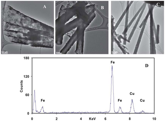
The synthesized Fe nanotubes were liberated from the template by dissolving the PC membrane in 5 mL methylene chloride. The morphology and aspect ratio of the Fe nanotubes were identified using TEM. Various sizes Fe nanotubes were successfully synthesized using the above-mentioned procedure (Fig. 1). The outer diameters of the tubes were found to be 411 ± 44 nm, 211 ± 26 nm, and 130 ± 19 nm (N ≥ 50 tubes) for PC membranes with 400, 200, 100 nm pore sizes, respectively. The corresponding inner diameters were found to be 400 ± 40, 200 ± 20, and 105 ± 10 nm. Although the length of the as-synthesized Fe nanotubes is controlled by the thickness of the PC membrane, the smaller diameter nanotubes were longer than the larger ones, which might be attributed to the increase in mechanical strength as the size decreases. As shown in Fig. 1, the length of the as-synthesized nanotubes is in the range of 2–5 μm. For simplification, 400, 200, 100 nm are used throughout this article to designate the different as-prepared Fe nanotubes. in order to maintain the rough texture of the nanotubes surface, which is desirable for higher reactive surface area; no further annealing was done (see ESI†, Fig. S2).
Fig. 1.
TEM images of Fe nanotubes synthesized using PC membrane with (A) 400 nm, (B) 200 nm, (C) 100 nm pore sizes, and (D) EDS analysis of 400 nm Fe nanotubes.
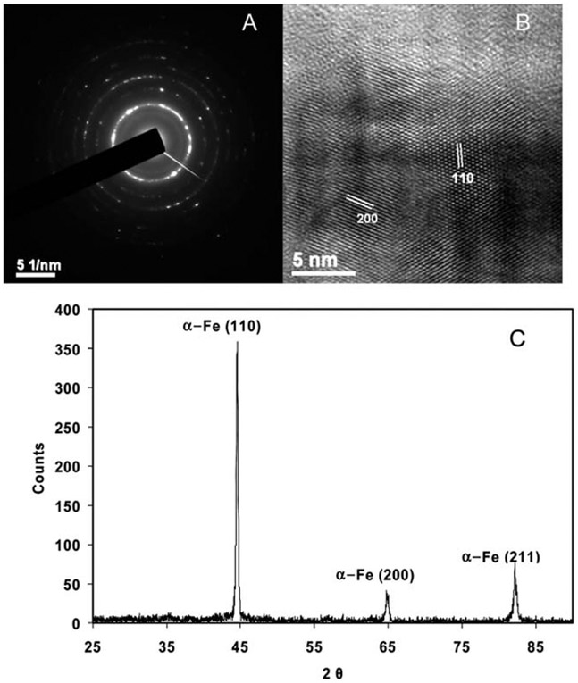
The crystal structure of the Fe nanotubes was controlled by the concentration of the reactants. At higher concentrations of NaBH4 and FeSO4, organized amorphous structures were observed (see ESI†, Fig. S3). On contrary, at lower concentrations, the as-synthesized Fe nanotubes had a polycrystalline structure. The HRTEM image, Fig. 2B, shows the different crystalline domains, with the values between the planes matching that of the cubic crystal structure. Further, the selected area electron diffraction (SAED) pattern shown in Fig. 2A is consistent with polycrystalline nature of the Fe nanotubes. The SAED pattern was analyzed with the CHT diffraction analysis script87 on the digital micrograph software (see ESI†, Fig. S4) to determine the lattice spacing of various crystalline domains. The analysis showed six different crystalline domains (110), (200), (211), (220), (310), and (222) with lattice spacings of 2.0268, 1.4332, 1.1702, 1.0134, 0.9064, and 0.8275 Å, respectively. The SAED pattern matches exactly that of the Fe polycrystalline body centered cube (BCC), JCPDS (006-0696), which indicates the high purity of the as-prepared Fe nanotubes. To further elucidate the crystallinity and purity of the Fe nanotubes, powder XRD measurements were acquired for the dry powder (dried under nitrogen atmosphere) of the liberated Fe nanotubes. The XRD pattern (Fig. 2C) shows three peaks at 2θ of 44°, 65°, and 80° which represent the (110), (200), (211) crystalline domains. This pattern matched with Fe syn, JCPDS (006-0696). No iron oxide peak was found in the XRD or EDS spectra. This suggests that any iron oxide that may be present on the metallic iron nanotubes is below the detection limit of XRD, which is in the range of 3–5%. We attribute this high purity to the use of ascorbic acid during the reaction, which maintains the produced Fe nanotubes in a reducing medium and inhibits the formation of iron oxide on the surface of the tube. The high purity of the ZVI nanotubes is desirable for the subsequent deposition of the palladium shell onto the Fe nanotubes as well as for high reactivity in aqueous solution to produce the hydrogen required in the hydrodehalogenation reactions.
Fig. 2.
Crystalline characterization of the as-synthesized Fe nanotubes: (A) SAED pattern, (B) HRTEM image, and (C) XRD spectrum of the dry powder of the nanotubes. The same crystalline structure was noticed for Fe nanotubes of different sizes prepared from 1 × 10⁻³ M iron (II) sulfate, 1 × 10⁻² M ascorbic acid, and 1 × 10⁻² M NaBH4 as a typical concentration of the reactants.
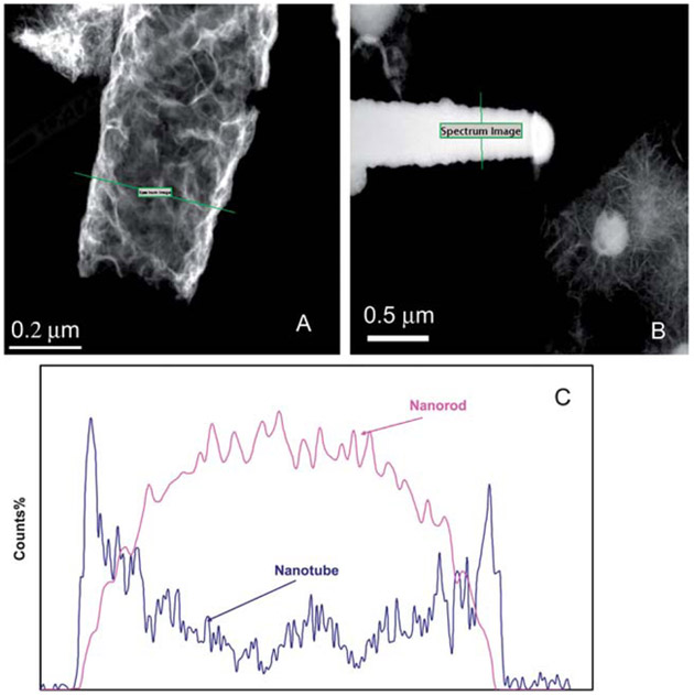
Although, the hollow nature of the as-prepared Fe nanotube is evident from the low magnification TEM images (Fig. 1), further elucidation of the hollow structure of the Fe nanotubes was performed using the EDS line mapping in STEM mode. A 1 nm electron probe was scanned across the as-synthesized Fe nanotube and a Fe nanorod, while recording the Fe signal at a 1 s dwell time. The “bell” shape of the Fe Kα EDS peak of the Fe nanorod (Fig. 3) represents the high intensity of the material in the center of the nanorod (solid interior). On contrary, the “saddle” shape of the Fe Kα EDS profile of the nanotube indicates the hollow interior of the as-synthesized Fe nanotubes, which in turn provides a high surface area for the deposition of palladium nanoparticles. Electroless deposition of a palladium layer was achieved by soaking the freshly prepared Fe nanotube in an alcoholic solution of 0.5% w/v palladium acetate according to the following equation:
It is expected that the presence of acetate prevents Fe2+ from reprecipitating as iron hydroxide on the surface.
Fig. 3.
Hollow interior of the as-synthesized Fe nanotubes: (A) EDS line mapping of Fe Kα across the as-synthesized Fe nanotube, (B) EDS line mapping of Fe Kα across Fe nanorod, and (C) the comparable probe position peak profile.
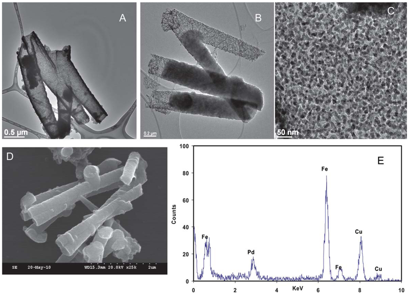
The new material was characterized by TEM, SEM, BET and ICP-AES. As shown in the low magnification TEM images (Fig. 4), the as-synthesized Fe nanotubes maintain their aspect ratio after deposition of the palladium layer. This indicates good mechanical strength of the as-synthesized Fe nanotubes. It is also evident that the Pd is deposited on the available surface area of the Fe nanotubes as a uniform layer of bound nanoparticles. The presence of Pd particles on the Fe nanotube surface is noticeable by comparing the TEM image of the Fe nanotubes in Fig. 1 to the Pd/Fe nanotubes in Fig. 4. The Pd/Fe nanotubes maintain a hollow interior after the deposition of the Pd layer. This fine structure provides with high exposed surface area for catalytic reactions. This hypothesis was further elucidated by multi-point N2-BET surface area analysis. The BET surface area of the as-synthesized Pd/Fe nanotubes was found to be 74.6 ± 8.8 m2 g−1 (average ± one standard deviation from triplicate analysis of a sample) as measured by nitrogen adsorption analysis. The surface area of the nanotube was also calculated geometrically (as that of a hollow cylinder) based on TEM measurements of the inner and outer diameter of the nanotube, and it was found to be 51 m2 g−1. This geometrically calculated area does not take into consideration the surface roughness due to the deposited Pd, which may explain its lower value than the surface area obtained through BET analysis. The BET surface area was used for all subsequent calculations of the kinetics of the dechlorination reaction.
Fig. 4.
Characterization of the morphology of as-synthesized Pd/Fe nanotubes: (A) TEM image of 400 nm Pd/Fe nanotubes, (B) TEM image of 200 nm Pd/Fe nanotubes, (C) HRTEM image of 400 nm Pd/Fe nanotubes, (D) SEM of 200 nm Pd/Fe nanotubes, and (E) EDS analysis of 400 nm Pd/Fe nanotubes.
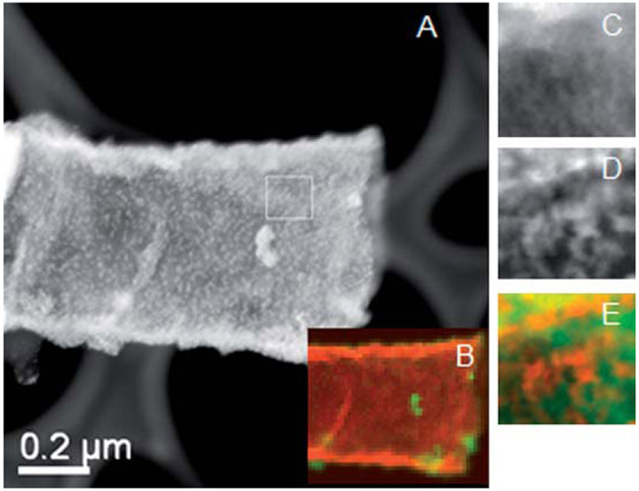
The elemental composition of the as-synthesized Pd/Fe nanotubes was determined by EDS analysis. The EDS spectra in Fig. 4 show a peak at 2.81 keV assigned to Pd Lα, which confirmed the presence of Pd in the sample. The composition of the as-synthesized Pd/Fe nanotubes was determined by EDS analysis to be 97.8% Fe and 2.2% Pd. No oxygen peak was observed suggesting minimal oxidation of the metallic iron after the deposition of palladium particles. These results are consistent with the 97.5% Fe and 2.5% Pd obtained by ICP-AES analysis. Formation of a highly dispersed uniform shell of palladium is very desirable because it leads to greater catalytic surface area. The morphology of the Pd shell was studied by dark field scanning transmission electron microscopy (DF-STEM). As evident from Fig. 5, the Pd nanoparticles are well dispersed as a uniform shell on the core Fe nanotubes. Further, EDS mapping for Fe and Pd was performed on STEM mode using a 1 nm electron probe with a dwell time of 0.5 s. The Fe Kα and Pd Lα profiles were simultaneously detected over a 48 × 40 pixel area, the designated square in Fig. 5. The EDS maps in Fig. 5 represent the 3-D distribution of Fe and Pd in the as-synthesized Pd/Fe nanotubes. As evident from the images, the Pd nanoparticles are distributed on the surface of the Fe nanotubes with very high dispersion, which provides with very high catalytic surface area. It is also worth noting that the Pd/Fe nanotubes maintained large surface area even in aggregation as evident from (see ESI†, Fig. S5).
Fig. 5.
Characterization of the palladium distribution on the as-synthesized Fe nanotubes: (A) DF-STEM image of 400 nm Pd/Fe nanotube, (B) color mix image of the EDS mapping of Fe and Pd across a whole nanotube, (C) EDS map of Fe with high resolution, (D) EDS map of Pd with high resolution, and (E) color mix image of Fe map and Pd map.
Dechlorination of PCB 77
For comparison purposes, Pd/Fe nanoparticles (ESI†, Fig. S6) were prepared according to literature procedures with some modifications.36,39,88 Specifically, ascorbic acid was used to stabilize the FeSO4 solution and prevent the oxidation of the produced Fe particles. This condition was used to mimic the solutions used in the preparation of Fe nanotubes. It was found by XRD (ESI†, Fig. S7) that the Pd/Fe nanoparticles prepared with this procedure exhibit metallic iron BCC polycrystalline structure similar to that of Pd/Fe nanotubes. It is also evident from the XRD spectrum of Pd/Fe nanoparticles in Fig. S7 (ESI†) that the amount of oxidized Fe as a result of the surface reaction of depositing Pd nanoparticles is below the detection limit of XRD. This condition was desirable for high efficiency of the dechlorination of PCB 77. The particle size was found by TEM to be about 25 ± 10 nm with a core of about 20 nm ZVI particles and a layer of very small palladium particles (see ESI†, Fig. S6). It has been established that the palladium content has a direct influence on the efficiency of dechlorination reactions.12,89 Accordingly, Pd/Fe nanoparticles were prepared that had a palladium content consistent with that of the as-synthesized Pd/ Fe nanotubes as determined by ICP-AES. The Pd/Fe nanoparticles were found to have 15.5 ± 2.8 m2 g−1 average BET surface area. It should be noted that there are other Pd/Fe nanoparticle systems reported, such as those in which the particles are supported within membranes.40,90–92 In this study and for comparison purposes, we use a membrane-free Pd/Fe nanoparticle system that had a similar Pd content to that of the as-synthesized Pd/Fe nanotubes.
3,3′,4,4′-Tetrachlorobiphenyl (PCB 77), a single PCB congener, was chosen as a model compound for studying the dechlorination efficiency of the as-synthesized Pd/Fe nanotubes. It has been found that coplanar PCBs, such as PCB 77, are aryl hydrocarbon receptor (AhR) agonists that could cause cardiovascular diseases.93 It has also been shown that PCB 77 induces cytochrome P450 1A1 (CYP1A1), which may lead to oxidative stress.94
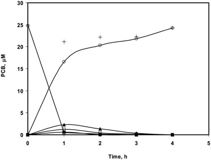
Pd/Fe nanotubes of 400 nm in diameter were used in the dechlorination of PCB 77 as described in the Experimental section. Along with PCB 77, the dechlorinated products PCB 37, PCB 35, PCB 15, PCB 13, PCB 12, PCB 11, PCB 3, PCB 2, and biphenyl were monitored. The results of the dechlorination of PCB 77 in a solution containing 25 μM PCB 77 by 1 mg mL−1 metal loading are depicted in Fig. 6. About 95% of PCB 77 was dechlorinated, mainly to biphenyl and trace concentrations of lower chlorine-content PCB intermediates, within the first hour of the reaction. Besides biphenyl, very small amounts of mono- and di-chlorobiphenyl, and practically no PCB 77 were determined after two hours of reaction.
Fig. 6.
Dechlorination profile of PCB 77 using 400 nm Pd/Fe nanotubes with metal loading 1 mg mL−1 and 2.5% Pd-to-Fe ratio: (∆) tetrachlorobiphenyl, PCB 77, (■) trichlorobiphenyl, PCB 37 + PCB 35, (▲) dichlorobiphenyl, PCB 11 + PCB 12 + PCB 13 + PCB 15, (□) mono-chlorobiphenyl, PCB 2 + PCB 3, (○) biphenyl, and (+) carbon balance.
We hypothesize that palladium is deposited on both the exterior and interior surface of the nanotubes and consequently dechlorination takes place on both surfaces. In order to evaluate the effect of the internal surface of the Pd/Fe bimetallic nanotubes on the efficiency of the dechlorination reaction, Fe nanorods of 400 nm diameter were synthesized by carrying out the U-tube template-based electroless reaction for extended period of time to attain complete nucleation within the pores of the membrane template. Subsequently, palladium was deposited on the surface of the Fe nanorods in a manner similar to the one on Fe nanotubes. The Pd/Fe bimetallic nanorods exhibited much slower dechlorination rate with about 90% dechlorination in 24 h, which, when compared with the data in Fig. 7, indicate that the internal surface of the nanotubes contributes to the high efficiency of dechlorination of the synthesized Pd/Fe bimetallic nanotubes.
Fig. 7.
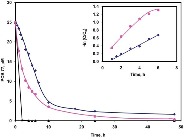
Comparison of the dechlorination efficiency of Pd/Fe nanoparticles and Pd/Fe nanotubes: (♦) 0.1 mg mL−1 400 nm Pd/Fe nanotubes, (●) 1 mg mL−1 Pd/Fe nanoparticles, and (▲) 1 mg mL−1 400 nm Pd/Fe nanotubes. Inset: linear fit kinetics of the dechlorination of 25 μM PCB 77 with (●) 1 mg mL−1 Pd/Fe nanoparticles and (♦) 0.1 mg mL−1 400 nm Pd/Fe nanotubes.
It is well established that the rate of metal-promoted dechlorination of chlorinated organic compounds depends not only on their concentration, but also on the available reactive and catalytic surface area of the metal. Accordingly, a pseudo-first order kinetic model has been generally used to describe the rate of the dechlorination reaction.92
Where C is the concentration of PCB 77 (mol L−1) at time t, ρm is the metal loading (g L−1), and aS is the specific surface area of the metal nanostructures. The surface area normalized constant, kSA, is widely used to give meaningful comparison between different systems.
To study the kinetics of the dechlorination of PCB 77 using the Pd/Fe nanotubes, we decreased the metal loading to 0.1 mg mL−1. This slows down the reaction, so we can follow the rate of degradation of PCB 77. Fig. 7 shows a comparison of the degradation of 25 μM PCB 77 using 1 mg mL−1 Pd/Fe nanotubes, 0.1 mg mL−1 Pd/Fe nanotubes, and 1 mg mL−1 Pd/Fe nanoparticles. The dechlorination using 1 mg mL−1 Pd/Fe nanotubes is much faster than using the same amount of Pd/Fe nanoparticles. However, when using 0.1 mg mL−1 Pd/Fe nanotubes, the dechlorination rate was similar to the 10-fold higher Pd/Fe nanoparticles. The data for the degradation of PCB 77 were fit to a first order kinetic model (Fig. 7, inset) yielding kobs of 0.18 h−1 and 0.16 h−1 for Pd/Fe nanoparticles and nanotubes, respectively. BET analysis was used to obtain aS values, which were subsequently used to calculate the BET-normalized kSA. Accordingly, the kSA values were calculated to be 0.012 L h−1 m−2 and 0.022 L h−1 m−2 for the bimetallic nanoparticles and nanotubes, respectively. These kSA values indicate high efficiency of degradation of PCB 77 using the as-synthesized Pd/Fe nanotubes. Consequently, less metal loading can be used to perform the degradation of the halogenated organics, which decreases the environmental concern of using palladium.
It should be noted that the selectivity of dechlorination of polychlorinated biphenyls depends on the position of the chlorine atom. It has been generally observed using metallic nanoparticles that the resistivity of the substituted chlorine to dechlorination follows the order ortho ≫ meta > para.95,96 This dechlorination profile of PCB 77 was also observed in the present studies irrespective of whether Pd/Fe nanotubes or nanoparticles were used. This similar dechlorination selectivity indicates that the curvature of the nanotubes has no effect, within the error, on the selectivity of the dechlorination reaction.
Conclusion
We described the synthesis and characterization of a new class of materials based on Pd/Fe bimetallic nanotubes. The metallic Fe nanotubes were prepared by a simple approach under ambient conditions and subsequently coated with Pd to create Pd/Fe nanotubes. The bimetallic nanotubes are composed of a core of Fe nanotubes covered with a shell of palladium nanoparticles. The synthesized Pd/Fe nanotubes have tailored morphology controlled by the template pore size. The reaction time and the concentrations of the electrolytes were found to have great effect on the morphology and crystal structure of the nanotubes. Pd/Fe nanotubes were used in dechlorination of PCB 77 as halogenated compound. In comparison with Pd/Fe nanoparticles, the Pd/Fe bimetallic nanotubes showed higher reactivity in dechlorination of PCB 77. Pd/Fe nanotubes can be effectively used in remediation of different other persistent organic pollutants.
Supplementary Material
Acknowledgements
The authors acknowledge support from the NIEHS-SRP program (P42ES007380).
Footnotes
Electronic supplementary information available: Optical image of the U-shape reaction tube, TEM images of Pd/Fe nanotubes and nanoparticles and analysis of the SAED pattern of the Pd/Fe nanotubes. See DOI: 10.1039/c1jm11435b
References
- 1.Bell AT, Science, 2003, 299, 1688–1691. [DOI] [PubMed] [Google Scholar]
- 2.Barbara PF, Acc. Chem. Res, 1999, 32, 387–387. [Google Scholar]
- 3.Kaur A and Gupta U, J. Mater. Chem, 2009, 19, 8279–8289. [Google Scholar]
- 4.Talapin DV, Lee JS, Kovalenko MV and Shevchenko EV, Chem. Rev, 2010, 110, 389–458. [DOI] [PubMed] [Google Scholar]
- 5.Bracey CL, Ellis PR and Hutchings GJ, Chem. Soc. Rev, 2009, 38, 2231–2243. [DOI] [PubMed] [Google Scholar]
- 6.Katz E and Willner I, Angew. Chem., Int. Ed, 2004, 43, 6042–6108. [DOI] [PubMed] [Google Scholar]
- 7.Heath JR, Science, 1995, 270, 1315–1316. [Google Scholar]
- 8.Eustis S and El-Sayed MA, Chem. Soc. Rev, 2006, 35, 209–217. [DOI] [PubMed] [Google Scholar]
- 9.El-Sayed MA, Acc. Chem. Res, 2004, 37, 326–333. [DOI] [PubMed] [Google Scholar]
- 10.Goodman DW, Nature, 2008, 454, 948–949.18719574 [Google Scholar]
- 11.Ponder SM, Darab JG and Mallouk TE, Environ. Sci. Technol, 2000, 34, 2564–2569. [Google Scholar]
- 12.Xu J and Bhattacharyya D, Ind. Eng. Chem. Res, 2007, 46, 2348–2359. [Google Scholar]
- 13.Joo SH and Zhao D, Chemosphere, 2008, 70, 418–425. [DOI] [PubMed] [Google Scholar]
- 14.Kinkead B and Hegmann T, J. Mater. Chem, 2010, 20, 448–458. [Google Scholar]
- 15.Roduner E, Chem. Soc. Rev, 2006, 35, 583–592. [DOI] [PubMed] [Google Scholar]
- 16.Hu JT, Odom TW and Lieber CM, Acc. Chem. Res, 1999, 32, 435–445. [Google Scholar]
- 17.Narayanan R, Tabor C and El-Sayed MA, Top. Catal, 2008, 48, 60–74. [Google Scholar]
- 18.Li Y, Hong XM, Collard DM and El-Sayed MA, Org. Lett, 2000, 2, 2385–2388. [DOI] [PubMed] [Google Scholar]
- 19.Schlogl R and Abd Hamid SB, Angew. Chem., Int. Ed, 2004, 43, 1628–1637. [DOI] [PubMed] [Google Scholar]
- 20.Campbell CT, Science, 2004, 306, 234–235. [DOI] [PubMed] [Google Scholar]
- 21.Meier MAR, Filali M, Gohy JF and Schubert US, J. Mater. Chem, 2006, 16, 3001–3006. [Google Scholar]
- 22.Luo CC, Zhang YH and Wang YG, J. Mol. Catal. A: Chem, 2005, 229, 7–12. [Google Scholar]
- 23.Gauthard F, Epron F and Barbier J, J. Catal, 2003, 220, 182–191. [Google Scholar]
- 24.Serov A and Kwak C, Appl. Catal., B, 2009, 90, 313–320. [Google Scholar]
- 25.Tsuji J, Palladium Reagents and Catalysts: New Perspectives for the 21st Century, John Wiley & Sons, Inc., Chichester, West Sussex, Hoboken, NJ, 2004. [Google Scholar]
- 26.Calo V, Nacci A, Monopoli A and Cotugno P, Angew. Chem., Int. Ed, 2009, 48, 6101–6103. [DOI] [PubMed] [Google Scholar]
- 27.Rahim EH, Kamounah FS, Frederiksen J and Christensen JB, Nano Lett, 2001, 1, 499–501. [Google Scholar]
- 28.Cassol CC, Umpierre AP, Machado G, Wolke SI and Dupont J, J. Am. Chem. Soc, 2005, 127, 3298–3299. [DOI] [PubMed] [Google Scholar]
- 29.Li ZP, Gao J, Xing XT, Wu SZ, Shuang SM, Dong CA, Paau MC and Choi MMF, J. Phys. Chem. C, 2010,114, 723–733. [Google Scholar]
- 30.Ogasawara S and Kato S, J. Am. Chem. Soc, 2010,132, 4609–4613. [DOI] [PubMed] [Google Scholar]
- 31.Lee CL, Tseng CM, Wu RB, Wu CC and Syu SC, Electrochim. Acta, 2009, 54, 5544–5547. [Google Scholar]
- 32.Peng ZM and Yang H, J. Am. Chem. Soc, 2009, 131, 7542–7543. [DOI] [PubMed] [Google Scholar]
- 33.Marx S and Baiker A, J. Phys. Chem. C, 2009, 113, 6191–6201. [Google Scholar]
- 34.Dash P, Dehm NA and Scott RWJ, J. Mol. Catal. A: Chem, 2008, 286, 114–119. [Google Scholar]
- 35.Grittini C, Malcomson M, Fernando Q and Korte N, Environ. Sci. Technol, 1995, 29, 2898–2900. [DOI] [PubMed] [Google Scholar]
- 36.Wang CB and Zhang WX, Environ. Sci. Technol, 1997, 31, 2154–2156. [Google Scholar]
- 37.Kim JH, Tratnyek PG and Chang YS, Environ. Sci. Technol, 2008, 42, 4106–4112. [DOI] [PubMed] [Google Scholar]
- 38.Tee YH, Bachas L and Bhattacharyya D, J. Phys. Chem. C, 2009, 113, 12616–12616. [DOI] [PMC free article] [PubMed] [Google Scholar]
- 39.Zhang WX, J. Nanopart. Res, 2003, 5, 323–332. [Google Scholar]
- 40.Venkatachalam K, Arzuaga X, Chopra N, Gavalas VG, Xu J, Bhattacharyya D, Hennig B and Bachas LG, J. Hazard. Mater, 2008, 159, 483–491. [DOI] [PMC free article] [PubMed] [Google Scholar]
- 41.Nurmi JT, Tratnyek PG, Sarathy V, Baer DR, Amonette JE, Pecher K, Wang CM, Linehan JC, Matson DW, Penn RL and Driessen MD, Environ. Sci. Technol, 2005, 39, 1221–1230. [DOI] [PubMed] [Google Scholar]
- 42.He F and Zhao DY, Environ. Sci. Technol, 2005, 39, 3314–3320. [DOI] [PubMed] [Google Scholar]
- 43.Li F, Vipulanandan C and Mohanty KK, Colloids Surf., A, 2003, 223, 103–112. [Google Scholar]
- 44.Zheng ZH, Yuan SH, Liu Y, Lu XH, Wan JZ, Wu XH and Chen J, J. Hazard. Mater, 2009, 170, 895–901. [DOI] [PubMed] [Google Scholar]
- 45.Xu J, Dozier A and Bhattacharyya D, J. Nanopart. Res, 2005, 7, 449–467. [Google Scholar]
- 46.Iijima S, Nature, 1991, 354, 56–58. [Google Scholar]
- 47.Xia YN, Yang PD, Sun YG, Wu YY, Mayers B, Gates B, Yin YD, Kim F and Yan YQ, Adv. Mater, 2003, 15, 353–389. [Google Scholar]
- 48.Kijima T, Yoshimura T, Uota M, Ikeda T, Fujikawa D, Mouri S and Uoyama S, Angew. Chem., Int. Ed, 2004, 43, 228–232. [DOI] [PubMed] [Google Scholar]
- 49.Collins PG, Zettl A, Bando H, Thess A and Smalley RE, Science, 1997, 278, 100–103. [Google Scholar]
- 50.Zhu Y, Liu FP, Ding WP, Guo XF and Chen Y, Angew. Chem., Int. Ed, 2006, 45, 7211–7214. [DOI] [PubMed] [Google Scholar]
- 51.Sun YG, Wiley B, Li ZY and Xia YN, J. Am. Chem. Soc, 2004, 126, 9399–9406. [DOI] [PubMed] [Google Scholar]
- 52.Remskar M, Adv. Mater, 2004, 16, 1497–1504. [Google Scholar]
- 53.Boldt R, Kaiser M, Kohler D, Krumeich F and Ruck M, Nano Lett, 2010, 10, 208–210. [DOI] [PubMed] [Google Scholar]
- 54.O’Dwyer C, Navas D, Lavayen V, Benavente E, Santa Ana MA, Gonzalez G, Newcomb SB and Torres CMS, Chem. Mater, 2006, 18, 3016–3022. [Google Scholar]
- 55.Sun YG, Mayers B and Xia YN, Adv. Mater, 2003,15, 641–646. [Google Scholar]
- 56.Nishizawa M, Menon VP and Martin CR, Science, 1995, 268, 700–702. [DOI] [PubMed] [Google Scholar]
- 57.Kim SW, Kim M, Lee WY and Hyeon T, J. Am. Chem. Soc, 2002, 124, 7642–7643. [DOI] [PubMed] [Google Scholar]
- 58.She GW, Shi WS, Zhang XH, Wong TL, Cai Y and Wang N, Cryst. Growth Des, 2009, 9, 663–666. [Google Scholar]
- 59.Liu XY, Zeng JH, Zhang SY, Zheng RB, Liu XM and Qian YT, Chem. Phys. Lett, 2003, 374, 348–352. [Google Scholar]
- 60.Rao CNRN, J. Chem. Soc., Dalton Trans, 2003, 1–25. [Google Scholar]
- 61.Ma DK, Hu XK, Zhou HY, Zhang JH and Qian YT, J. Cryst. Growth, 2007, 304, 163–168. [Google Scholar]
- 62.Hulteen JC and Martin CR, J. Mater. Chem, 1997,7, 1075–1087. [Google Scholar]
- 63.Martin CR, Science, 1994, 266, 1961–1966. [DOI] [PubMed] [Google Scholar]
- 64.Brumlik CJ and Martin CR, J. Am. Chem. Soc, 1991, 113, 3174–3175. [Google Scholar]
- 65.Martin CR, Chem. Mater, 1996, 8, 1739–1746. [Google Scholar]
- 66.Lee W, Scholz R, Niesch K and Gosele U, Angew. Chem., Int. Ed, 2005, 44, 6050–6054. [DOI] [PubMed] [Google Scholar]
- 67.Zhang X, Wang H, Bourgeois L, Pan R, Zhao D and Webley PA, J. Mater. Chem, 2008, 18, 463–467. [Google Scholar]
- 68.Chen H, Elabd YA and Palmese GR, J. Mater. Chem, 2007, 17, 1593–1596. [Google Scholar]
- 69.Steinhart M, Wehrspohn RB, Gosele U and Wendorff JH, Angew. Chem., Int. Ed, 2004, 43, 1334–1344. [DOI] [PubMed] [Google Scholar]
- 70.Mao YB and Wong SS, J. Am. Chem. Soc, 2004, 126, 15245–15252. [DOI] [PubMed] [Google Scholar]
- 71.Zhang F, Sfeir MY, Misewich JA and Wong SS, Chem. Mater, 2008, 20, 5500–5512. [Google Scholar]
- 72.Zhou HJ and Wong SS, ACS Nano, 2008, 2, 944–958. [DOI] [PubMed] [Google Scholar]
- 73.Steinhart M, Jia ZH, Schaper AK, Wehrspohn RB, Gosele U and Wendorff JH, Adv. Mater, 2003, 15, 706–709. [Google Scholar]
- 74.Cui CH, Li HH and Yu SH, Chem. Commun, 2010, 46, 940–942. [DOI] [PubMed] [Google Scholar]
- 75.Chen C, Loo J, Deng M, Kox R, Huys R, Bartic C, Maes G and Borghs G, J. Phys. Chem. C, 2009, 113, 5472–5477. [Google Scholar]
- 76.Sander MS and Tan LS, Adv. Funct. Mater, 2003, 13, 393–397. [Google Scholar]
- 77.Sun YG and Xia YN, Adv. Mater, 2004, 16, 264–268. [Google Scholar]
- 78.Tao FF, Guan MY, Jiang Y, Zhu JM, Xu Z and Xue ZL, Adv. Mater, 2006, 18, 2161–2164. [Google Scholar]
- 79.Verbeeck J, Lebedev OI, Van Tendeloo G, Cagnon L, Bougerol C and Tourillon G, J. Electrochem. Soc, 2003, 150, E468–E471. [Google Scholar]
- 80.Cao HQ, Wang LD, Qiu Y, Wu QZ, Wang GZ, Zhang L and Liu XW, ChemPhysChem, 2006, 7, 1500–1504. [DOI] [PubMed] [Google Scholar]
- 81.Xu XJ, Yu SF, Lau SP, Li L and Zhao BC, J. Phys. Chem. C, 2008, 112, 4168–4171. [Google Scholar]
- 82.Cao XL and Liang YG, Mater. Lett, 2009, 63, 2215–2217. [Google Scholar]
- 83.Huang CW and Hao YW, Nanotechnology, 2009, 20, 445607–445607. [DOI] [PubMed] [Google Scholar]
- 84.Xu Y, Xue DS, Fu JL, Gao DQ and Gao B, J. Phys. D: Appl. Phys, 2008, 41, 215010–215010. [Google Scholar]
- 85.Martin CR, Vandyke LS, Cai ZH and Liang WB, J. Am. Chem. Soc, 1990, 112, 8976–8977. [Google Scholar]
- 86.Cochran RE, Shyue JJ and Padture NP, Acta Mater, 2007, 55, 3007–3014. [Google Scholar]
- 87.Mitchell DRG, Ultramicroscopy, 2008, 108, 367–374. [DOI] [PubMed] [Google Scholar]
- 88.Ponder SM, Darab JG, Bucher J, Caulder D, Craig I, Davis L, Edelstein N, Lukens W, Nitsche H, Rao LF, Shuh DK and Mallouk TE, Chem. Mater, 2001, 13, 479–486. [Google Scholar]
- 89.Johnson TL, Scherer MM and Tratnyek PG, Environ. Sci. Technol, 1996, 30, 2634–2640. [Google Scholar]
- 90.Lewis S, Smuleac V, Montague A, Bachas L and Bhattacharyya D, Sep. Sci. Technol, 2009, 44, 3289–3311. [DOI] [PMC free article] [PubMed] [Google Scholar]
- 91.Smuleac V, Bachas L and Bhattacharyya D, J. Membr. Sci, 2010, 346, 310–317. [DOI] [PMC free article] [PubMed] [Google Scholar]
- 92.Xu J and Bhattacharyya D, Environ. Prog, 2005, 24, 358–366. [Google Scholar]
- 93.Hennig B, Meerarani P, Slim R, Toborek M, Daugherty A, Silverstone AE and Robertson LW, Toxicol. Appl. Pharmacol, 2002, 181, 174–183. [DOI] [PubMed] [Google Scholar]
- 94.Ramadass P, Meerarani P, Toborek M, Robertson LW and Hennig B, Toxicol. Sci, 2003, 76, 212–219. [DOI] [PubMed] [Google Scholar]
- 95.Arbon RE, Mincher BJ and Knighton WB, Environ. Sci. Technol, 1994, 28, 2191–2196. [DOI] [PubMed] [Google Scholar]
- 96.Yak HK, Lang QY and Wai CM, Environ. Sci. Technol, 2000, 34, 2792–2798. [Google Scholar]
Associated Data
This section collects any data citations, data availability statements, or supplementary materials included in this article.


