Abstract
Smartphones have shown promise as an enabling technology for portable and distributed point-of-care diagnostic tests. The CMOS camera sensor can be used for detecting optical signals, including fluorescence for applications such as isothermal nucleic acid amplification tests. However, such analysis is typically limited mostly to endpoint detection of single targets. Here we present a smartphone-phone based image analysis pipeline that utilizes the CIE xyY (chromaticity-luminance) color space to measure the luminance (in lieu of RGB intensities) of fluorescent signals arising from nucleic acid amplification targets, with a discrimination sensitivity (ratio between the positive to negative signals) which is an order of magnitude more than traditional RGB intensity based analysis. Furthermore, the chromaticity part of the analysis enables reliable multiplexed detection of different targets labeled with spectrally separated fluorophores. We apply this chromaticity-luminance formulation to simultaneously detect Zika and chikungunya viral RNA via endpoint RT-LAMP (Reverse transcription Loop-Mediated isothermal amplification). We also show real time LAMP detection of Neisseria gonorrhoeae samples down to a copy number of 3.5 copies per 10 μL of reaction volume in our smartphone-operated portable LAMP box. Furthermore, the chromaticity-luminance analysis is readily adaptable to other types of multiplexed fluorescence measurements using a smartphone camera.
Graphical Abstract
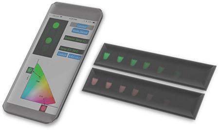
High discrimination of multiplexed fluorescence assays using a smartphone camera.
Introduction
The union between consumer electronics and medical diagnostics is becoming ubiquitous in the scientific literature. Portable smartphone cameras with their built-in image processing capabilities are already being used for optical interrogation of biological and chemical assays, which traditionally have required fluorometers, spectrophotometers or other dedicated benchtop plate readers. Moreover, as the image quality of smartphone cameras (both in terms of pixel count and CMOS sensor quality) is continuously improving following Moore’s law trend, there has been a natural push for smartphones to penetrate the world of biosensors and field portable diagnostics. Consequently, several groups have harnessed the versatility and small footprint of smartphones for both in vivo and in vitro testing, using either built-in smartphone sensors or data transmission capabilities to connect to peripheral components of existing diagnostic systems1–5.
The utility of smartphone cameras as standalone biosensors can be divided into two categories, namely (i) resolution-based analysis and (ii) emission/color based analysis. For resolution based analysis, researchers have harnessed the continually increasing pixel density on smartphone CMOS sensors to resolve micro to nano-scale features6. This has enabled smartphone microscopy7, cell image analysis8 and even nano-scale analysis9. On the other end, the CMOS pixel array has also been used to analyze the color and fluorescence intensity of biological assays. Examples include smartphone based detection of changes in pH in sweat or saliva1, colorimetric quantification of vitamin D levels10, nano-particle enabled enhanced signal ELISA assays11 and more recently, fluorescence-based detection of isothermal nucleic acid amplification reactions12,13. However, these applications do not provide quantitative results and smartphones have still not replaced dedicated optical detectors for high precision quantification of emission/color based assays due to some key challenges. Firstly, the color balancing functions of a conventional cell phone are optimized for photography in high ambient light and are not suited for performing accurate quantitative measurements of images. Furthermore, even though there have been quantum dot based fluorophores that are more amenable for RGB analysis 14,15, the emission wavelength of typical organic fluorophore molecules do not generally align with the base vector wavelengths of RGB color space of the CMOS sensors. For these reasons, the use of smartphone cameras has typically been limited to simple yes/no or end-point detection, which can be accomplished by human eyes in most cases. A smartphone-based detector should be able to go beyond this level of analysis and provide quantitative results if it is to be used as a stand-alone optical detector in point of care settings.
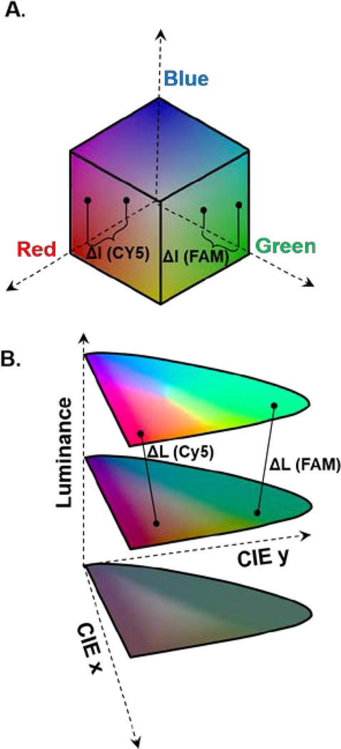
We address this issue by transforming the smartphone-acquired images from the cubic RGB color space (Fig. 1A) to CIE xyY color space where the luminance (intensity of signal) is orthogonal to the color space (Fig. 1B). This transformation enables us to determine the illumination intensity (luminance) independently of the color (emission wavelength) of the fluorophore molecules, resulting in higher dynamic range.
Fig. 1. Conversion for RGB cubic color space to CIE Chromaticity-Luminance orthogonal color space.
(A) The RGB color space consisting of red, blue and green as base axes are not optimal for fluorescence discrimination. (B) The CIE Chromaticity-Luminance color decouples the color aspect of the signal (planar) from the luminance.
Theory
Modern smartphone cameras utilize a CMOS imaging sensor array with three channels sensitive to the long, middle, and short wavelength visible lights (to mimic the human eye). This is usually implemented by using a Bayer color filter array placed on top of a monochrome sensor chip, where each pixel is designed to detect only one of the three primary colors. Upon light impingement onto the sensor chip surface, every pixel, depending on the wavelength range of the microfilter on top of it, acquires a stimulus value on one of the three primaries, which can be mathematically described as the interaction between the illumination source, the spectrum of the object and sensor parameters:
where I(λ) is the power spectral distribution function of the light source; O(λ) is the characteristic spectral response of the sample; and Sr(λ), Sg(λ), and Sb(λ) are the spectral sensitivity curves of the red, green, and blue color channels of the Bayer filters equipped on the sensor, respectively. The acquired RGB values of the three primaries then undergo a series of post-processing steps which include demosaicing, color mapping, white balance, denoising, and compression. Both Apple and Android smartphone CMOS sensors have an inbuilt encoder which renders the sensor array data into a compressed JPEG, PNG or TIFF data file rather than direct sensor output (RAW file). The resulting R, G, and B (post-processed RGB) values of the three primaries for each pixel form an RGB sensor triplet.
Color-map transformations that convert RGB to chromaticity-luminance based form has been shown to increase the sensitivity of the sensor to changes in the luminosity of the signal16. Therefore, we propose to map each post-processed RGB triplet to the CIE XYZ color space which is an absolute mathematical abstraction of the human color perception and is one of the most widely used color reference model17.
Methods
We produced a smartphone app that performs the following image analysis protocol on a bioassay performed in a well, imaged by a smartphone:
-
(i)
The app crops a circular region around the bio-assay and then selects a rectangular section within the cropped area for image analysis (Figure S1) from which the post-processed RGB values are extracted.
-
(ii)We apply a gamma transformation to the RGB values to account for the non-linear response of the pixel intensity values obtained from the sensor18.
Where Ɣ is the gamma factor and α1 and α2 are gamma correction factors (Supp. Info.). - (iii)
-
(iv)The XYZ tristimulus values can then be normalized to characterize the Luminance of a color by the Y value and the chromaticity of a color by two non-negative values, x and y (white point designated by x = y =1/3).
The x, y coordinate pair forms a form a tongue-shaped CIE x−y chromaticity diagram representing all colors (Fig. 1B). By definition, the chromaticity value of a color is independent of the luminance of the color, so it contains the intensity-independent spectral information of an object and is thus the optimal parameter to describe color change induced spectral shift.
-
(v)
The color of the sample can be determined from the x-y values of the sample, and colors can be distinguished from each other by superimposing the points on the chromaticity diagram.
-
(vi)
We can then take the ratio of Luminance values of the samples to the luminance value of the background. We call this value luminance discrimination (L*) which now becomes a new metric to quantify the strength of the fluorescence signal independently from the color.
-
(vii)We can define a luminance difference in this color space as the Euclidean distance between two-color stimulus with the following equation
Where ΔL is the change in luminance between two points in the xyY color space. -
(viii)For real-time detection of fluorescence amplification, quantification is performed by applying a sigmoidal fit to the luminance versus time data20 as follows
where Lmax and Lo, represent the maximum and background Luminance values, respectively. The quantities t1/2 and k express the time required for intensity to reach half of the maximum value and slope of the curve, respectively, and were used as fitting parameters.These image analysis and calculations steps are all performed in the smartphone app called LAMP2Go (Figure S2). The LAMP box consists of an isothermal heater and RGB LED source both of which are operated with smartphone app via Bluetooth connection enabling portable diagnostics (Figure S3).
Results and Discussion
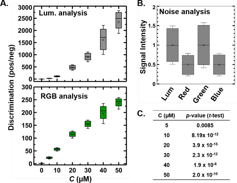
As a first demonstration of measuring samples of different fluorescent intensity, we analyzed a series of DNA solution with a varying amount of SYTO 9 intercalating dye. The samples were illuminated using the blue channel of a red-green-blue LED source coupled with a triple bandpass filter. The emitted signals were filtered through a green bandpass. Fixing the intensity and wavelength of the excitation source without any interference of external light and enabling background subtraction in our calculations greatly facilitates our system to work with different smartphones without the need of any color calibration. The sample response was measured by the smartphone camera for each sensor pixel in two ways: (i) by measuring the inbuilt post-processed RGB values in the green channel and (ii) by measuring the Luminance value from the chromaticity luminance color space. The results were compared with the 8-bit color image of the samples by replacing each color value at individual pixel location with the corresponding green channel intensity (RGB color space) and Luminance value (CIE xyY color space) (Figure S4). Even though the distinction may not appear significantly great when inspected by eye, the discrimination (ratio of intensities of positive and negative samples) is nearly an order of magnitude higher when pixels are analyzed in the Chromaticity-Luminance color space as compared to the RGB color space (Fig. 2A). In negative samples (with no fluorophore) the luminance and the RGB intensities are comparable, with similar amounts of noise (Fig. 2B). Furthermore, the p-values from a statistical t-test (which signifies the signal strength compared to the noise in two distributions) performed between the luminance and RGB distributions are extremely low (in O(10−8) – O(10−12)) for samples that exhibit significant fluorescence emission (Fig. 2C). These results suggest a significant increase in the dynamic range of fluorescent signals in the luminance space as compared to RGB space with a negligible increase in signal noise.
Fig 2. Comparison between Chromaticity-Luminance based analysis with RGB based analysis.
(A) Measuring the Luminance in CIE xyY color space significantly increases the dynamic range of fluorescent signals in comparison to green channel intensities in the RGB color space while (B) keeping the relative noise of the signal (no fluorescence) unaltered under luminance and RGB analysis. (C) p-values from t-test (two tail) compares the signal strength to the noise between the luminance and RGB distributions for samples with varying fluorescence emission (Null hypothesis: There is no statistically significant difference between the luminance and RGB sample sets). Discrimination is defined as the ratio of positive sample to the intensity of the sample with no fluorophore. In the box plots (A, B) the boundary of the box closest/furthest to the zero indicates 25th/75th percentile, black line and cross within the box indicate the median and mean respectively and whiskers above/below the box indicate 1 standard deviation of the distribution of over a 3 sample replicate and 1000 pixels analysis (3000 data points for each distribution).
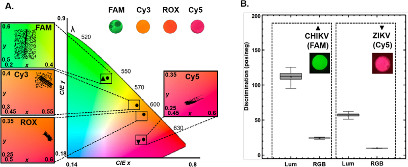
Analyzing the CIE x-y coordinates of the different samples yields spectrally separate chromaticity islands corresponding to multiple emission wavelengths enabling us to even distinguish between fluorophores with spectrally close emission wavelengths such as Cy3 and ROX (Fig. 3A). We applied this framework with QUASR RT-LAMP (Methods Supp. Info.) to simultaneously detect Zika (ZIKV) and chikungunya (CHIKV) viral targets using primers sets labeled with Cy5 for ZIKV and FAM for CHIKV (Fig 3A). When analyzed on the luminance scale, we find that discrimination between positive and negative viral assays is again significantly higher when compared to performing the analysis in RGB color space (Fig. 3B). Together, Chromaticity-Luminance analysis enables the smartphone to be transformed into a more reliable fluorescence detector with a digitally enhanced dynamic range enabling easily interpretable results and the capability to perform multiplexed detection.
Fig 3. Differential detection of multiple fluorophore targets on CIE xy coordinate system.
(A) Multiple fluorophore-labeled samples (SYTO 9/FAM, Cy3, ROX, and Cy5) can be easily distinguished by mapping them on spectrally separated regimes on the chromaticity plot. The four zoomed in insets on color map shows the distribution of the individual fluorophore signals (3000 pixels over 3 sample replicate for each fluorophore). (B) Duplex endpoint QUASR RT-LAMP21 detection of ZIKV/CHIKV (Positive reactions contained 10 PFU/μL of viral). Samples (ZIKV/CHIKV) were illuminated with Red/Blue light and the analyzed images were mapped on chromaticity diagram (A) overlapping with the clearly distinguishable Cy5/FAM fluorophore emission islands. (B) The discrimination between positive and negative viral samples for both Cy5 and FAM assays are significantly higher in the Luminance space when compared to their corresponding RGB intensities. The box plot parameters in (B) have the same parameters as the parameters of boxplots in Fig. 2.
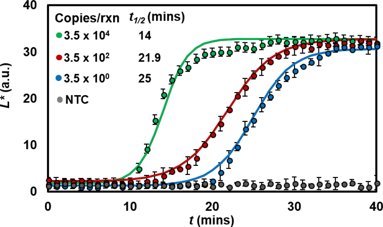
We wanted to see if we can extend the application to quantitative analysis in addition to yes/no (endpoint) analysis. We applied the chromaticity-luminance algorithm to quantify real-time LAMP of Neisseria gonorrhoeae (Methods Supp. Info). Target samples were added at various concentrations to the LAMP mix containing 2 μM SYTO 9 and incubated at 65 °C on our portable LAMP box setup for 40 minutes. We then used our app to automate fluorescence image acquisition of the samples every minute during the amplification, using the blue LED source for illumination. Unlike PCR, which is a discrete cycling process, LAMP is a continuous process and there is no well-defined cycle time. Particularly at the low range of target concentration, real-time LAMP curves tend to provide semi-quantitative information about target quantity. Nevertheless, we can apply a standard two parameter sigmoidal fit20 to the luminance data extracted from each sequence of images, enabling us to fit an amplification curve growth parameter (t1/2; time required for the luminance values to reach half of its maximum value). We first note that the luminance accurately captures the lag, exponential and plateau phases of nucleic acid amplification curves and is capable of detecting samples containing N. gonorrhoeae down to 3.5 copies/μL (Fig. 4). As a comparison, we evaluated the same series of reactions in a benchtop real-time PCR instrument and found that results are very similar (Figure S4). We also compared the real time luminance analysis with RGB analysis and found that even though the green channel intensity of the post-processed RGB values also increases with time, the resulting amplification curves do not capture the exponential nature of the signal growth as captured by luminance discrimination (Figure S5).
Fig. 4. Quantitative analysis of nucleic acid amplification on the smartphone.
Measured normalized luminance values as a function of reaction time for four initial template copy number (N. gonorrhoeae DNA samples). Quantification is achieved by applying sigmoidal fits to these data (mean ± sd of 3 replicates) and using t1/2 as an amplification parameter for each curve. The analysis is able to detect N. gonorrhoeae DNA down to a copy number of 3.5 copies/rxn (10μL of reaction volume).
Conclusion
We have shown how image processing and recasting the smartphone-captured image intensities into a color independent form enables us to quantify fluorescence-based nucleic acid amplification more reliably and accurately than a conventional post-processed RGB analysis. The purpose of this image processing pipeline is to decouple the color aspect of the image from the luminance values and to override the auto-adjustment of the camera parameters, granting manual control over the focal length, exposure time, and ISO of the CMOS sensor lens (all of which affect the intensity of the collected signal). Once optimized for an assay, these parameters can be saved, allowing all subsequent assays to be performed with the same settings. The familiar and intuitive application environment (iOS and Android) cuts down the software learning curve and minimizes the need for new users to familiarize themselves with instrument operations.
This kind of analysis also offers new avenues for multiplexed detection of fluorescent signals. Although the human eye can differentiate millions of colors, it is still challenging to objectively differentiate between spectrally similar fluorophore assays for multiplexed detection. Here we have shown how the smartphone can be used to reproducibly and reliably quantify colorimetric sensing of nucleic acid samples without any human vision biases. Our results show that under the luminance-based analysis, the positive/negative discrimination is about an order of magnitude higher than conventional RGB analysis. This suggests a new way of applying luminance based measurements to analyze fluorescent signals and build a next generation smartphone based optical sensing algorithms. The engineered decoupling of luminance from the color of assay signals also enables us to perform real-time detection of nucleic acid amplification via LAMP, a feature that was previously not possible to our knowledge with smartphone cameras. Such tools would make bioanalytical analysis and detection more accessible not just to scientists and engineers but also to the general public.
Supplementary Material
Acknowledgment
This paper describes objective technical results and analysis. Any subjective views or opinions that might be expressed in the paper do not necessarily represent the views of the U.S. Department of Energy or the United States Government. This work was funded by the National Institute of Allergy and Infectious Disease (NIH: NIAID) Grant 1R21AI120973 (R. Meagher). Sandia National Laboratories is a multimission laboratory managed and operated by National Technology & Engineering Solutions of Sandia, LLC, a wholly owned subsidiary of Honeywell International Inc., for the U.S. Department of Energy’s National Nuclear Security Administration under contract DE-NA0003525.
Footnotes
Associated Content
Table of LAMP primers used to amplify Zika, chikungunya and N. gonorrhoeae virus strain, image processing parameters, MATLAB script for color space conversion and images showing spectral response of iPhone camera and real time amplification comparison between luminance and RGB analysis.
References
- (1).Oncescu V; O’Dell D; Erickson D Lab on a Chip 2013, 13, 3232–3238. [DOI] [PubMed] [Google Scholar]
- (2).Shen L; Hagen JA; Papautsky I Lab on a Chip 2012, 12, 4240–4243. [DOI] [PubMed] [Google Scholar]
- (3).Lopez-Ruiz N; Curto VF; Erenas MM; Benito-Lopez F; Diamond D; Palma AJ; Capitan-Vallvey LF Analytical chemistry 2014, 86, 9554–9562. [DOI] [PubMed] [Google Scholar]
- (4).Priye A; Ugaz VM Biosensors and Biodetection: Methods and Protocols Volume 1: Optical-Based Detectors 2017, 251–266. [Google Scholar]
- (5).Priye A; Wong S; Bi Y; Carpio M; Chang J; Coen M; Cope D; Harris J; Johnson J, et al. Analytical chemistry 2016, 88, 4651–4660. [DOI] [PMC free article] [PubMed] [Google Scholar]
- (6).Ozcan A Lab on a chip 2014, 14, 3187–3194. [DOI] [PMC free article] [PubMed] [Google Scholar]
- (7).Lee SA; Yang C Lab on a Chip 2014, 14, 3056–3063. [DOI] [PMC free article] [PubMed] [Google Scholar]
- (8).Knowlton S; Sencan I; Aytar Y; Khoory J; Heeney M; Ghiran I; Tasoglu S Scientific reports 2015, 5, 15022. [DOI] [PMC free article] [PubMed] [Google Scholar]
- (9).Wei Q; Qi H; Luo W; Tseng D; Ki SJ; Wan Z; Göröcs Z; Bentolila LA; Wu T-T, et al. ACS Nano 2013, 7, 9147–9155. [DOI] [PMC free article] [PubMed] [Google Scholar]
- (10).Lee S; Oncescu V; Mancuso M; Mehta S; Erickson D Lab on a Chip 2014, 14, 1437–1442. [DOI] [PubMed] [Google Scholar]
- (11).Roda A; Michelini E; Cevenini L; Calabria D; Calabretta MM; Simoni P Analytical chemistry 2014, 86, 7299–7304. [DOI] [PubMed] [Google Scholar]
- (12).Ganguli A; Ornob A; Yu H; Damhorst G; Chen W; Sun F; Bhuiya A; Cunningham B; Bashir R Biomedical microdevices 2017, 19, 73. [DOI] [PubMed] [Google Scholar]
- (13).Priye A; Bird SW; Light YK; Ball CS; Negrete OA; Meagher RJ Scientific Reports 2017, 7. [DOI] [PMC free article] [PubMed] [Google Scholar]
- (14).Algar WR; Krull UJ Analytica Chimica Acta 2007, 581, 193–201. [DOI] [PubMed] [Google Scholar]
- (15).Petryayeva E; Algar WR; Medintz IL Applied spectroscopy 2013, 67, 215–252. [DOI] [PubMed] [Google Scholar]
- (16).Yu H; Le HM; Kaale E; Long KD; Layloff T; Lumetta SS; Cunningham BT Journal of pharmaceutical and biomedical analysis 2016, 125, 85–93. [DOI] [PubMed] [Google Scholar]
- (17).Wyszecki G; Stiles WS Color science; Wiley; New York, 1982; Vol. 8. [Google Scholar]
- (18).Forsyth DA; Ponce J Computer vision: a modern approach 2003, 88. [Google Scholar]
- (19).Hunt RWG; Pointer MR Measuring colour; John Wiley & Sons, 2011. [Google Scholar]
- (20).Rutledge R Nucleic acids research 2004, 32, e178–e178. [DOI] [PMC free article] [PubMed] [Google Scholar]
- (21).Ball CS; Light YK; Koh C-Y; Wheeler SS; Coffey LL; Meagher RJ Analytical chemistry 2016, 88, 3562–3568. [DOI] [PubMed] [Google Scholar]
Associated Data
This section collects any data citations, data availability statements, or supplementary materials included in this article.


