Abstract
Introduction
To implement the modulated arc total body irradiation (MATBI) technique within the existing infrastructure of a radiation oncology department. The technique needed to treat paediatric patients of all ages, some of whom would require general anaesthesia (GA).
Methods
The MATBI technique required minor modifications to be incorporated within existing departmental infrastructure. Ancillary equipment essential to the technique were identified and in some cases custom designed to meet health and safety criteria. GA equipment was also considered. To evaluate the effectiveness of the implemented technique, an audit of the cases clinically treated was conducted.
Results
A motorised treatment couch was designed to allow the patient to be positioned in stabilisation equipment at a height, then lowered to the floor to accommodate source‐to‐skin‐distances from 180 cm to 198 cm to treat the fixed 40 cm × 40 cm field size. Treatment couch design also facilitated positioning of the bespoke two‐part spoiler. While organ at risk dose is limited using a beam weight optimisation technique, the dose is further reduced using compensators placed close to the patient's skin on a 3D printed custom‐made support bridge. A digital radiography system is used to verify compensator position. Fifteen patients have been treated to date for various diseases using a variety of dose fractionations ranging from 2 Gy in a single fraction to 12 Gy in 6 fractions. Five patients have required GA due to age or behavioural issues.
Conclusion
The modified MATBI technique and the equipment required for treatment delivery has been found to be well tolerated by all patients.
Keywords: Modulated arc therapy, paediatric cancers, total body irradiation
Introduction
In late 2014, with the opening of the Lady Cilento Children's Hospital Brisbane, Radiation Oncology Princess Alexandra Hospital ‐ Raymond Terrace (ROPART) became the primary provider of paediatric radiation therapy services in Queensland. As a result, a Total Body Irradiation (TBI) protocol needed to be developed and implemented as TBI had not previously been offered by the department. Primarily patients diagnosed with acute forms of leukaemia, aplastic anaemia and non‐Hodgkin's lymphoma will undergo chemotherapy in conjunction with TBI in preparation for a hematopoietic stem‐cell transplant or bone marrow transplant.1 Paediatric patients referred to ROPART range in age from 1 to 18 years.
Initially the project team conducted an extensive evidence‐based review of different TBI techniques.2 The decision was made based on specific criteria, including requirements for 3D planning, the use of lung and kidney compensation and a preference for minimal use of additional bolus. The department was equipped with the Pinnacle3 treatment planning system (TPS) versions 9.8 and 14.0 (Philips Healthcare, Fitchburg, WI), two Somatom Open computed tomography (CT) scanners (Siemens Medical Solutions, Forchheim, Germany) for planning purposes and four Clinac iX (Varian Medical Systems, Palo Alto, CA) linear accelerators (linacs). Each linac is equipped with onboard imaging (OBI) capabilities. TBI technique selection was also dependant on its suitability for implementation within existing infrastructure. Ultimately two options were presented to the multi‐disciplinary team for consideration, a lateral field‐in‐field (FIF) technique3 and the anterior posterior modulated arc total body irradiation (MATBI) technique.4 The existing bunkers within the department are 7.1 m × 7.2 m in size and their layout precluded the use of a lateral FIF technique. After preliminary dosimetric testing and review by the multi‐disciplinary oncology team, MATBI was chosen as the preferred technique.
MATBI is an anterior posterior technique requiring the patient to lie both supine and prone. Multiple static fields with a 3–5° gantry angle variation are positioned in an arc formation to treat the full length of the patient. Figure 1 shows a schematic of the beam arrangement used in MATBI. As described by Kirby et al.,4 MATBI is optimally treated at an extended source‐to‐skin distance (SSD) of approximately 200 cm. This is best achieved by the patient lying on a bed close to the floor. A Perspex spoiler positioned over the patient ensures full build‐up conditions on the patient's skin. Compensators are used to lower the dose delivered to organs at risk and are best placed as close to the skin surface as possible. A fixed field size of 40 cm × 40 cm and collimator rotation of 0° is used. At the time of implementation, this technique had not been previously used in Australia.
Figure 1.
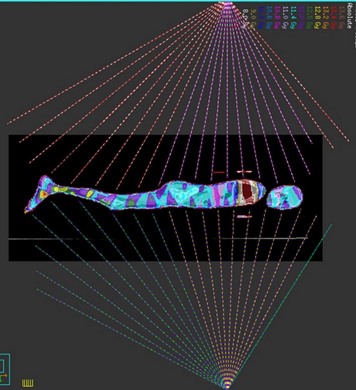
Schematic of beam arrangement for MATBI plan. Note anterior beams are delivered with the patient in the supine position.
Favourable features for implementing the MATBI technique included the facilitation of lung and kidney compensation and improved dose homogeneity over the length of the patient without the extensive use of bolus to equalise variations in separation. An inverse planning approach using the Pinnacle3 TPS beam weight optimisation option is able to be used to determine the monitor units required for each static field, optimising dose homogeneity throughout the body. This technique allowed for greater ease and accuracy of beam modelling data to be collected using a standard 3D water phantom. The MATBI technique required no physical modifications to the existing infrastructure in terms of room layout. However additional ancillary treatment and imaging equipment would be required as the OBI cannot be utilised for verification imaging of the compensators due to an extended SSD of around 200 cm. Consequently, an alternative imaging system needed to be sourced for use. This paper provides a framework for implementation of MATBI and focuses on the identification and design of ancillary equipment. The adaptations and modifications made to the MATBI technique, in order to implement TBI treatments at ROPART, will be discussed.
Method
Ancillary equipment
The selection of the MATBI technique required an assessment of the constraints inherent with the bunker design at ROPART. Part of the implementation process required equipment to be either purchased or constructed including the following:
TBI couch
Spoiler
Compensator bridge
Treatment verification imaging
Patient positioning and stabilisation equipment
General anaesthetic (GA) facilitation
TBI couch development
MATBI requires an extended SSD of approximately 200 cm. The treatment couch on the Clinac iX linac only allows for an SSD to the couch top of approximately 160 cm. At a setup SSD of 140 cm the maximum field size achievable is 56 cm × 56 cm and insufficient to cover the lateral separation of the majority of patients. Therefore, a treatment couch that would allow the patient to be lowered closer to the floor was needed.
Consideration for TBI couch design had to take into account the existing room infrastructure. The distance from the isocentre axis to the linac couch stand is 47.5 cm. Therefore, the total width of the TBI couch plus the spoiler needed to be less than 95 cm. Preferably the TBI couch would accommodate imaging equipment and be compatible with the safe and efficient placement of a compensator bridge.
The modified massage couch as described by Held et al.,5 whilst readily available, presented a number of occupational health and safety risks. Without wheels or castors, the massage couch would have to be physically lifted into position from its storage area increasing the risk of injury to staff. Also, the massage bed height cannot be altered to compensate for changes in patient separation.
Having an adjustable couch height was considered an important feature for staff occupational safety and efficiency. This feature allows the patient to be positioned on the TBI couch at a more ergonomically safe height. Once the patient is positioned, the TBI couch could be lowered to the calculated treatment SSD. This feature is also vital for the safe induction of a patient undergoing a GA and the safe movement of the patient between prone and supine positions.
Many commercially available hospital and nursing home beds either do not lower to the floor enough to enable a greater SSD than the linac couch or had large bed ends that could not be removed. Collaboration was sought with a manufacturing company for a bespoke couch with the following design features:
Height adjustable – motorised (battery or mains powered)
Minimum couch top height of 15 cm
Total width of 69 cm
Couch top length of 180 cm
Non‐metal top to reduce scatter
Must have a maximum weight restriction of 120 kg or greater
Hospital grade Perspex surface for cleaning and stability
Imaging panel space (3 cm) below the top surface
Lockable castors/wheels for manoeuvrability
Compensator bridge guide
Spoiler
Skin sparing is usually a desirable feature of megavoltage radiation therapy. However, for patients undergoing TBI, as leukaemic cells may circulate through or infiltrate the skin, it is advantageous to have the skin receive as close to the prescribed dose as possible. The use of a 1 cm thick Perspex screen, placed 10–15 cm from the patient's skin surface creates scatter electrons thereby increasing the dose to the patient's skin.6
The manufacture of the spoiler was dependant on the final TBI couch length and width. The height of the spoiler needed to be adjustable to accommodate a variety of patient separations and the inclusion of the compensator bridge. Spoiler design needed to allow for the safe and efficient placement and removal should the patient require assistance during treatment. Finally, spoiler length was based on a 75th percentile height of approximately 180 cm for an 18 year old male.7
Compensators and compensator bridge
Compensators are used during the treatment of TBI patients to reduce the toxicity to organs at risk. Mean lung doses of 10–12 Gy have been associated with increased risk of interstitial pneumonitis, so lead compensators are utilised to reduce the mean lung dose to 10 Gy.8 Kidney compensation may also be requested by the radiation oncologist (RO) and applied in the prone position. Compensators are manufactured from layers of lead shaped as per the outline marked on the planning CT scan by the RO. Compensator details are displayed in Table 1.
Table 1.
Compensator attenuation and thickness
| Number of lead sheets | |||||
|---|---|---|---|---|---|
| 1 | 2 | 3 | 4 | 6 | |
| Approximate attenuation (%) | 10 | 20 | 30 | 40 | 50 |
| Thickness (cm) | 0.28a | 0.56 | 0.84 | 1.12 | 1.68 |
Physical density of each lead sheet is 11.2 g/cm3.
For maximum benefit, compensators should be placed directly on the patient's surface. This limits the amount of primary beam incident on the patient under the blocks when being irradiated at oblique angles. Skin placement was not an option due to the weight of compensators for paediatric patients and the anatomical shape of the thorax made it difficult to keep the compensators level and in place. Alternatively, the compensators are placed on a flat surface as close to the patient's skin surface as possible. The compensator bridge was designed to accommodate a range of patient separations, to be stable and able to support up to 4kg and be radio‐translucent.
Treatment image verification
For compensator placement verification, the standard linear accelerator kV imaging equipment could not be used. Various computed radiography (CR) and digital radiography (DR) imaging systems were compared for image quality, efficiency or image assessment, accuracy of spatial information and user friendliness.
Patient positioning
Existing equipment was evaluated to create a comfortable and reproducible patient position. As only the prone CT data set is used for treatment planning, it was imperative that there was accurate replication of the patient position between prone and supine positions, including the head position. Ideally when lying prone, the posterior surface of the shoulders, buttocks, heels and posterior surface of the head need to be level and parallel to the treatment couch as if they would be lying supine.
Initial testing was performed using anthropomorphic phantoms of different sizes. This provided preliminary information on positioning issues. Secondary testing involved staff and children volunteers across a variety of ages, heights and weights. It was identified that equipment requirements for accurate positioning varied between patients due to the different patient sizes expected in a paediatric cohort.
General anaesthetic facilitation
Although every measure is taken to eliminate the use of daily anaesthesia, at times it is required. From the literature, GA is advised for patients less than three years of age.9
With any GA there are inherent risks involved, including nausea and vomiting, sore throat and reactions to medications.10 Extra care is needed when positioned prone, as the risks are potentially greater and include a decrease in cardiac output, inferior vena cava obstruction and pressure sores.11 If an emergency situation arises, it is critical that the anaesthetic team are provided fast and easy access to the patient.
Clinical review of MATBI at ROPART
An exemption from institutional ethics approval was granted (reference number HREC/16/QPAH/718) to perform an audit of the clinical cases treated since commencement of the department's paediatric service. Data collected included age, height, weight, disease type, delivered dose, number of treatment fields and use of general anaesthetic.
Results
Ancillary equipment
Treatment couch
The TBI couch has a maximum working height of 78 cm and lowers to a minimum floor to couch top distance of 14 cm (Fig. 2A and B). This provides a maximum SSD to the couch top of 216 cm. The TBI couch top is 69 cm wide, 188 cm long with two levels. The top surface of the couch supports the patient, stabilisation equipment and compensator support bridge while the second level accommodates the digital imaging panel. The distance between the two levels is 3 cm allowing for easy positioning and removal of the imaging panel. The TBI couch is made using hospital grade Perspex for infection control reasons. The non‐porous material makes it easy to clean and does not interfere with the image quality. The bespoke couch enabled the patients to be treated within the confines of existing bunker infrastructure and room layout.
Figure 2.
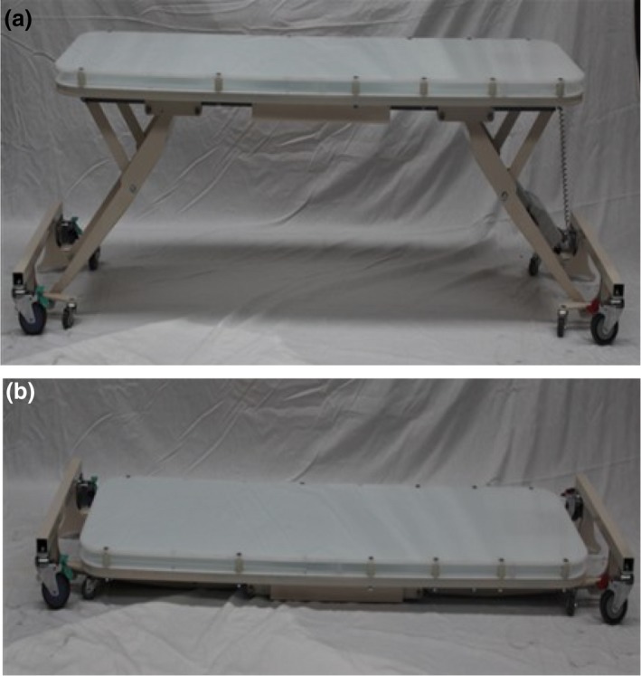
The treatment couch (supplied by Maxi‐Care Promotions Pty Ltd). (A) Full working height. (B) Lowered treatment position.
Spoiler
The open‐ended design of the spoiler optimises access for additional devices should a patient arrive with intravenous infusion equipment. Due to limitations in bunker size, the spoiler was manufactured in two halves that are locked together when positioned over the patient. The spoiler is 1 cm thick with a height ranging from 35 to 60 cm off the floor. The height of the spoiler is determined during the planning process to be positioned approximately 10 cm from the patient's skin surface (Fig. 3). The total width is 83 cm and the combined length of the two sections is 241 cm. The sides of the spoiler provide strength and allows the patient to easily view distraction devices. The spoiler was also constructed with lockable casters/wheels to aid in ergonomic and safe positioning over the patient.
Figure 3.
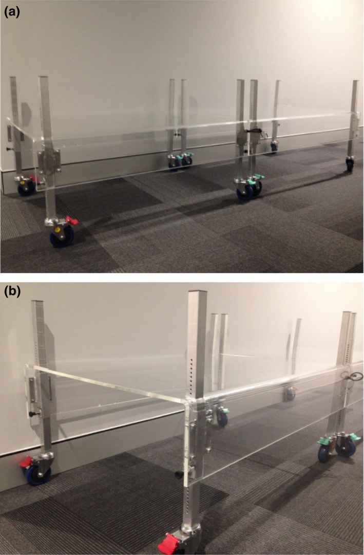
The spoiler. (A) Two‐part Spoiler connected. (B) Spoiler (end view).
Compensator and compensator bridge
TBI compensator blocks are suspended above the patient on a bridge constructed using 3D printed polylactic acid (PLA) plastic to minimise the effect on beam attenuation to <0.5% (Fig. 4). Two different sized compensator bridges were created to accommodate compensators of differing length or for cases where extra length is required to support kidney compensators. Each bridge is designed to accommodate a weight of up to 4 kg. The underside of the compensator bridge is set approximately 2 cm from the patient's skin surface. This allows for the patient's chest to rise and fall with breathing without touching the bridge. The compensator bridge was designed in‐house and, in part, constructed using a Makerbot2 3D printer (MakerBot Industries, Brooklyn, NY).
Figure 4.
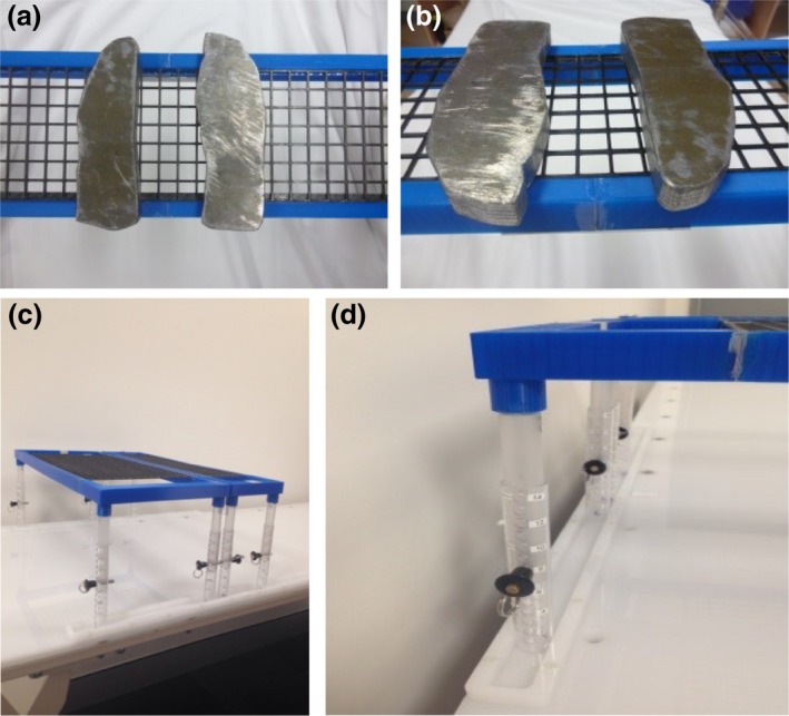
Compensators & Bridge. (A and B) Lung compensation blocks on bridge (C) Compensator bridges (large and small) (D) Compensator bridge in bad channels.
Channels made of the same hospital grade Perspex as the treatment couch were added along each edge of the TBI couch to prevent lateral movement of the compensator bridge during treatment. These channels therefore only allow the bridge to be moved superior or inferior to reposition compensators post imaging. This feature reduces the risk of potential injury to the patient from dislodged compensators (Fig. 4D).
Imaging
A Canon CXDI‐701C was purchased. This DR imaging system enables multiple pre‐treatment verification images to be acquired while leaving the cassette in place. Images are transferred via Wi‐Fi to the DR laptop. Treatment images are then easily transferred and saved to the MOSAIQ Oncology Management System (Elekta, Stockholm, Sweden), (Versions 2.4.1 & 2.6.0), for visual comparison against planning DRRs and for future reference. Image quality while not as high as early phantom testing indicated (Fig. 5A–C) has provided sufficient visualisation to confirm the accurate placement of the compensators.
Figure 5.
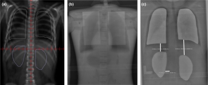
Compensator position on planning DRR versus treatment DR. (A) Digitally reconstructed radiograph (DRR) image. (B) Test Image. (C) Digital radiography (DR) image.
Patient positioning
Vacbags are utilised for all patients for both supine and prone positioning, generally encompassing the shoulders to the knees. Large foam boards and wedges placed under the prone vacbag raise the torso and legs of the patient to achieve the required flat posterior surface that is parallel to the treatment couch. The patient is set up in the prone position first as testing revealed that there are greater options to replicate the prone position when the patient is supine. Measurements are taken using various landmarks to aid reproducibility of the patient's position when supine. If a patient did not find lying with their head straight comfortable while in the prone position then a head turn to the left would be required. Head position must be consistent when repositioning between prone and supine. Table 2 shows the measurements taken to ensure consistent positioning between supine and prone set‐ups.
Table 2.
CT measurements
| Area | Measurement (cm) | |
|---|---|---|
| Prone | Supine | |
| Separation from table top (mid‐thorax) | ||
| Top of head – Top of shoulders | ||
| ITN – Top of shoulders | ||
| Tip of chin – Top of shoulders | ||
| RT shoulder – LT shoulder | ||
| RT inner elbow – CW | ||
| Lt inner elbow – CW | ||
| Iliac crest – malleolus | ||
| RT med malleolus – LT med malleolus | ||
ITN, Inferior Tragal Notch; RT, Right; LT, Left; CW, Chest Wall; Med, Medial.
Anaesthetic considerations
To assist with access to the patient's airway throughout the planning and treatment process, patients who require general anaesthesia are treated with their head turned to their left side. This also allows the anaesthetist to visualise the patient's face from the closed‐circuit television (CCTV) screen outside of the treatment room when prone. For the supine fields, the patient also has their head turned towards their left shoulder to ensure even dose through the head. While the face cannot be viewed in this position as it is facing away from the CCTV, the rise and fall of the chest is easily viewed and acceptable to the anaesthetic team.
Clinical review of MATBI at ROPART
Since the technique's inception early in 2015, 15 patients have been treated with the MATBI technique. Table 3 provides summary of patient‐specific information and treatment details. Patient ages ranged from 2 to 15 years while fractionation ranged from 1 to 6 fractions. Eleven patients received 12 Gy in 6 bi‐daily fractions while the remaining four patients received a single fraction with a prescribed dose ranging from 2.0 to 4.5 Gy. Total beam on time for these patients ranged from 30 to 80 min. The longer beam on time for Patients 2 and 10 was due to the higher fraction dose which required the dose to be delivered at a reduced dose rate of 100 MU/min and 60 MU/min for fields treating lung tissue.
Table 3.
A summary of patients treated between January 2015 and July 2017 using MATBI
| Patient | 1 | 2 | 3 | 4 | 5 | 6 | 7 | 8 | 9 | 10 | 11 | 12 | 13 | 14 | 15 |
|---|---|---|---|---|---|---|---|---|---|---|---|---|---|---|---|
| Age (years) | 10 | 10 | 13 | 6 | 15 | 2 | 7 | 13 | 3 | 11 | 15 | 4 | 6 | 13 | 15 |
| Disease | ALL | AML | ALL | ALL | ALL | ALL→AML | SAA | ALL | ALL | AML | ALL | ALL | ALL | BPDCN | ALL |
| Height (cm) | 137 | 135 | 163 | 119 | 165 | 92 | 135 | 153 | 92 | 167 | 159 | 101 | 124 | 162 | 198 |
| Weight (kg) | 28 | 22.5 | 53 | 24.3 | 42.9 | 15.9 | 29 | 60 | 15.2 | 65 | 74 | 16.5 | 28.8 | 71 | 75 |
| Fractions | 6 | 1 | 6 | 6 | 6 | 1 | 1 | 6 | 6 | 1 | 6 | 6 | 6 | 6 | 6 |
| Dose per fraction (Gy) | 2 | 4.5 | 2 | 2 | 2 | 2 | 3 | 2 | 2 | 3 | 2 | 2 | 2 | 2 | 2 |
| Beam number | 21(P) | 20(P) | 23(P) | 19(P) | 24(P) | 16(P) | 18(P) | 20(P) | 16(P) | 23(P) | 21(P) | 18(P) | 17(P) | 22(P) | 24(P) |
| 19(S) | 21(S) | 23(S) | 20(S) | 22(S) | 16(S) | 19(S) | 23(S) | 16(S) | 23(S) | 23(S) | 19(S) | 19(S) | 22(P) | 23(S) | |
| Beam on timea (mins) | 30 | 80 | 36 | 31 | 34 | 28 | 39 | 34 | 28 | 70 | 35 | 30 | 30 | 38 | 37 |
| Anaesthetic required | N | Y | N | N | N | Y | Y | N | Y | N | N | Y | N | N | N |
ALL, Acute Lymphoblastic Leukaemia; AML, Acute Myeloid Leukaemia; SAA, Severe Aplastic Anaemia; BPDCN, Blastic Plasmocytoid Dendritic Cell Neoplasm; P, Prone; S, Supine; N, No; Y, Yes.
Note the beam on time does not include set‐up time.
Five patients were treated while under GA (all single fractions). Due to developmental behavioural issues, a 7‐year‐old girl and 10‐year‐old boy were unable to comply with the position required for treatment despite play therapy. In these cases, the decision to use GA was in the best interest of the patient.
One patient's height of 198 cm exceeded the length of the TBI couch top. In this case the patient's head was positioned on the table top with the lower legs and feet supported above and over the end of the metal frame of the couch using a vacbag. The spoiler length easily covered the patient length. In vivo measurements confirmed no additional scatter was received to the ankles and feet.
Discussion
MATBI is the first TBI technique implemented at ROPART. The TBI investigation team were tasked with identifying a TBI technique that would accommodate paediatric patients ranging in age from 1 to 18 years, fit within current bunker infrastructure and be able to be delivered using a Clinac iX linear accelerator. To meet these constraints, custom designed equipment was required.
The height adjustable treatment couch was designed to allow greater ease and accuracy of setup compared with the original static massage table. A static height requires the patient to be setup at simulation on the linac to determine the treatment SSD,4 whereas an adjustable height removes this step. Staff and patient preferences have been mixed with regards to the adjustable height. The majority of the patients have found it easier to get onto the couch at a height close to the floor as it is easier to manoeuvre into the vacbag. Some staff prefer to setup the patient close to treatment height, whereas others raise the couch to a working height, including the anaesthetic team. The adjustable height allows individual preferences to be met and enables height adjustment for inter‐fraction setup variation.
While Held et al.5 opted not to use a spoiler, the literature supported the importance of increasing skin dose6 and there was an RO preference for its use, especially in the paediatric population. The spoiler was designed as two equal halves to improve manoeuvrability and has the advantage of easy and efficient placement and rapid removal. While there have been no emergency situations, staff report finding the two halves easy and efficient to manoeuvre in the tight spaces required.
The DR system employed for compensator placement verification is the first use of its type in radiation therapy and in particular, TBI treatment. DR imaging allows for real‐time assessment of compensator positioning reducing time the patient is required to remain motionless, therefore increasing accurate placement of compensators. While this system improves treatment efficiency compared with other options, it does pose a challenge to staff due to infrequent use and poor image quality. As a result, there continues to be a training session with the treating team prior to each TBI patient. This session aims to refresh staff on setup considerations and equipment use, including the DR system. Feedback from staff suggests this approach allows more efficient treatment flow and improves staff confidence.
Patient comfort is vital to ensure the patient remains still during dose delivery. The only patient comfort issue needing to be addressed and not initially anticipated was the post‐planning insertion of a prophylactic nasogastric (NG) tube due to potential mucositis. If the NG tube is placed in the right nostril, positioning the head turned to the left is uncomfortable. This has been mitigated through communication and education of appropriate paediatric hospital staff.
Clinical challenges experienced have been minimal with the greatest challenge being the 198 cm male patient and a couch length of 188 cm. The lower legs required additional support over and above the metal couch end frame. This was successfully achieved with no measurable scatter from the couch to the patient. In summary 15 patients of varying ages and heights have been treated with 5 of the 15 patients requiring GA.
Conclusion
The MATBI technique has been successfully implemented within the existing bunker infrastructure and clinical environment within ROPART. Although only a small number of patients have been treated to date, the design of the equipment developed has easily accommodated a wide range of patient ages and sizes, with and without the use of anaesthetic equipment.
Conflict of Interest
The authors declare no conflict of interest.
Acknowledgments
The authors acknowledge the following people and organisations for their contribution to the implementation of this technique within ROPART: Andrew Pullar (Radiation Oncologist – ROPART), Robyn Cheuk (Radiation Oncologist – ROPART) and Maxi‐Care Productions Pty Ltd. (W & V Kelly – Company Directors).
J Med Radiat Sci 65 (2018) 291–299
References
- 1. Barker C, LoSasso T, Wolden S. Total body irradiation In: Hoppe R, Phillips TL, Roach M., III (eds). Leibel and Phillips Textbook of Radiation Oncology, 3 edn. Elsevier Health Sciences; 2010; 279–302. [Google Scholar]
- 2. Peters M, Taylor B, Turner E. An evidence‐based review of total body irradiation. J Med Imaging Radiat Sci 2015; 46: 442–9. [DOI] [PubMed] [Google Scholar]
- 3. Onal C, Sonmez A, Arslan G, Sonmez S, Efe E, Oymak E. Evaluation of field‐in‐field technique for total body irradiation. Int J Radiat Oncol Biol Phys 2012; 83: 1641–8. [DOI] [PubMed] [Google Scholar]
- 4. Kirby N, Held M, Morin O, Fogh S, Pouliot J. Inverse‐planned modulated‐arc total‐body irradiation. Med Phys 2012; 39: 2761–4. [DOI] [PubMed] [Google Scholar]
- 5. Held M, Kirby N, Morin O, Pouliot J. Dosimetric aspects of inverse‐planned modulated‐arc total‐body irradiation. Med Phys 2012; 39: 5263–71. [DOI] [PubMed] [Google Scholar]
- 6. Roberts K, Chen Z, Seropian S. Total‐Body and Hemibody Irradiation In: Haplerin EC, Perez CA, Brady LW. (eds). Perez and Brady's principles and practice of radiation oncology, 5th edn Williams & Wilkins, Lippincott, 2008; 364–77. [Google Scholar]
- 7. Data Table of Stature‐for‐age Charts [database on the Internet]. Atlanta. Centers for Disease Control and Prevention, 2000 [cited 2018 May 11] Available from: https://www.cdc.gov/growthcharts/html_charts/statage.htm#males.
- 8. Marks LB, Bentzen SM, Deasy JO, et al. Radiation dose‐volume effects in the lung. Int J Radiat Oncol Biol Phys 2010; 76(3 Suppl): S70–6. [DOI] [PMC free article] [PubMed] [Google Scholar]
- 9. McMullen KP, Hanson T, Bratton J, Johnstone PAS. Parameters of anesthesia/sedation in children receiving radiotherapy. Radiat Oncol 2015; 10: 65. [DOI] [PMC free article] [PubMed] [Google Scholar]
- 10. Verma V, Beethe AB, LeRiger M, Kulkarni RR, Zhang M, Lin C. Anesthesia complications of pediatric radiation therapy. Pract Radiat Oncol 2016; 6: 143–54. [DOI] [PubMed] [Google Scholar]
- 11. Edgcombe H, Carter K, Yarrow S. Anaesthesia in the prone position. Br J Anaesth 2008; 100: 165–83. [DOI] [PubMed] [Google Scholar]


