Abstract
BACKGROUND:
3D printing is an additive manufacturing process allowing the creation of solid objects directly from a digital file. We believe recent advances in additive manufacturing may be applicable to surgical instrument design. This study investigates the feasibility, design and fabrication process of usable 3D printed surgical instruments.
METHODS:
The computer aided design (CAD) package Solid Works (Dassault Systemes SolidWorks Corp., Waltham MA) was used to design a surgical set including hemostats, needle driver, scalpel handle, retractors and forceps. These designs were then printed on a selective laser sintering (SLS) Sinterstation HiQ (3D Systems, Rock Hill SC) using DuraForm EX Plastic. The final printed products were evaluated by practicing general surgeons for ergonomic functionality and performance, this included simulated surgery and inguinal hernia repairs on human cadavers. Improvements were identified and addressed by adjusting design and build metrics.
RESULTS:
Repeated manufacturing processes and redesigns led to the creation of multiple functional and fully reproducible surgical sets utilizing the user feedback of surgeons. Iterative cycles including design, production and testing took an average of 3 days. Each surgical set was built using the SLS Sinterstation HiQ with an average build time of 6 hours per set.
CONCLUSIONS:
Functional 3D printed surgical instruments are feasible. Advantages compared to traditional manufacturing methods include no increase in cost for increased complexity, accelerated design to production times and surgeon specific modifications.
Introduction
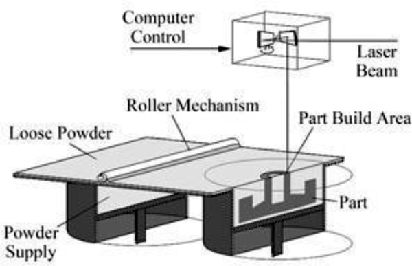
3D printing was born in the early to mid 1980’s and has appreciated a recent resurgence thanks to improved computing power, patent expirations and falling costs of the technology. Three broad categories of 3D printing exist, each unique in its method of creating solid objects from digital data. The earliest form of 3D printing, stereolithography (SLA), was developed by Charles Hull in the early 1980’s [1]. SLA employs liquid curable photopolymer and an activating laser to build solid parts in a layered manner. Hull later founded the company 3D Systems and developed the.STL file format that allows 3D printing machines to render digital files into a physical embodiment. S. Scott Crump developed fused deposition modeling (FDM) in the late 1980’s, eventually founding the company Stratasys [2]. FDM extrudes spooled printing material through a heated nozzle onto a build platform. The third variant of 3D printing is selective laser sintering (SLS), developed by Dr. Carl Deckard and Dr. Joseph Beaman at the University of Texas in Austin in 1987 [3]. SLS manufactures parts by melting, or sintering, plastic powder with a laser in a layered manner. As one layer is finished, a roller spreads a fresh layer of powder over the build area and the laser sinters the next layer. The powder in the build area acts as a supporting structure for any overhanging features. Once the build is complete, the area is raised and the part is taken to a breakout station for removal of excess powder. Once the excess powder and parts are separated, the powder can be reused in another build.
Within the surgical field 3D printing has been used to aid in training, create representative models or build biologic scaffolds [4]. The ease at which 3D imaging data can be converted to .STL file formats has facilitated many of these applications [5]. Fabrication of decellularized organs or scaffolds which accept seeding of live cells was pioneered by Uygun [6]. Built using hydroxyapatite, they are suitable for seeding with murine fibroblasts and support cellular growth [7,8]. By far the most popular and established application of 3D printing in the surgical field is within maxillofacial surgery where numerous reports exist describing surgical planning and production of implants or implant guides for surgical approach [9–13]. Other applications include production of anatomical phantom models to facilitate surgical training [12].
Use of 3D printing to create surgical instruments is limited. Kondor et al were the first to apply 3D printing to developing functional surgical instruments [14,15]. In their study they used a FDM style desktop printer from Stratasys to build a general surgical set. Advantages to 3D printed surgical instruments expressed in their paper were customization and ease of modification according to a clinician’s preferences. Functional testing of the instruments consisted of laparotomy, splenectomy and suturing on a surgical simulator known as a Cut Suit. In this present study the authors use CAD software and SLS to design, build and optimize a general surgical set for use in surgical simulation.
Methods
To prove the functionality of the instruments, inguinal hernia repairs were performed on male human cadavers. The Computer Aided Design (CAD) package SolidWorks was used to develop digital models of the surgical instruments (Dassault Systemes SolidWorks Corp., Waltham MA). Total design time was approximately 20 hours and an average of 4 iterations for each instrument was required to optimize functionality. These digital models were converted to the .stl file format and printed using the SLS Sinterstation HiQ (3D Systems, Rock Hill SC) in DuraForm EX Plastic. The instruments were manufactured in single build cycles using a combination of virgin and recycled DuraForm EX Plastic powder. The build envelope of the Sinterstation is W15 x D13 x H18 inches. To decrease build times and build volumes, the instruments were oriented such that build height was minimized. Actual build height for the general surgical set was 3 inches and build time for each set was 6 hours. Post processing included breaking the parts out of part cake and removing excess powder with a bead blaster. The instruments were not sterilized because they were to be tested in human cadavers.
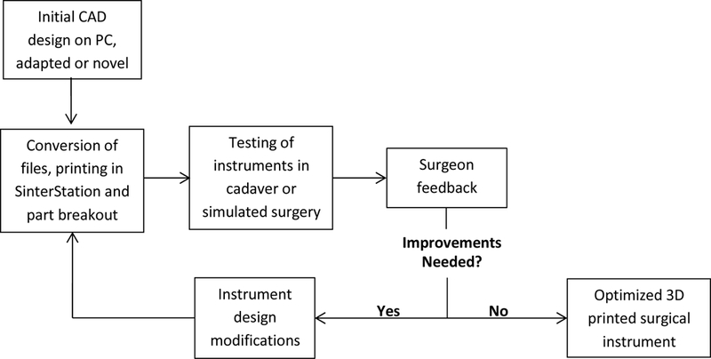
Due to material limitations of the DuraForm EX plastic, design adaptations from existing stainless steel instruments were neccessary. In our experience, the strength of the Duraform material was not sufficient to allow direct adaptation of instruments like a needle driver, hemostat, forcep, or scalpel handle. Figure 2 describes the workflow for adaptation of existing instruments or creation of novel ones to 3D printed instruments and their iterative improvement.
Figure 2.

Workflow diagram describing the iterative design cycle.
The key to the iterative process in Figure 2 is instrument testing and surgeon feedback. During cadaveric or simulated surgery, the performance of 3D printed surgical instruments is evaluated which drives design. This process is elaborated below in the description of the design processes for each instrument.
Results
Testing trials were done in two ways, simulated surgery and cadaveric inguinal hernia repairs. Simulated surgery consisted of handling the instruments and testing their functionality in a non-surgical setting. Design modifications from these simulations were driven by ergonomics. During the cadaveric surgical cycles, design modifications were driven by their performance during the steps required by the procedure. Table 1 describes the design iterations with regards to each instrument and how it was tested. There were three iterations of simulated surgery and two cadaveric hernia repairs performed to optimize the instruments. Brief descriptions of the instrument modifications that resulted from the iterative cycle are described.
Table 1.
Description of design modifications resulting from each iterative cycle.
| Iterative Cycle |
Iteration Type |
Army Navy | Scalpel Handel |
Forceps | Hemostats | Needle Driver |
|---|---|---|---|---|---|---|
| 1 | Simulated | Ribs added along length for strength | Multiple designs created | Finger grips added | Locking teeth refined | Tips adjusted for better approximation |
| 2 | Surgical | None | Fully reinforced model chosen | Cross hatched surface added to tips | Hinge modified to ↓ tip crossing | Hinge modified to ↓ tip crossing |
| 3 | Simulated | None | None | Resting position of arms widened | Handel adjusted for ↑ ergonomics | Total redesign |
| 4 | Surgical | Retractor blades strengthened | None | ↑ Thickness and resistance of arms | Arms | Handel hole diameter increased |
| 5 | Simulated | None | None | None | Tips strengthened | None |
Needle Driver
The needle driver’s dominant role during surgical testing was mesh placement and closing of skin. Suturing of mesh to the aponeurosis of the pubic tubercle required significant force to be applied to the suture needle by the needle driver. In early iterations of the needle drivers, this step was difficult because the needle driver end effector, or tips, would cross and drop the suture needle. This problem continued despite major design modifications at the instrument hinge. Feedback from attending surgeons and finite element analysis in Solid Works led to a new design iteration of the needle driver. The final design embeds one arm into the other, allowing equal distribution of force along the hinge’s axis of rotation and eliminating tip crossing. Two days after the original surgery this new needle driver design was tested and was found to have improved grasp and no tip crossing. The design time needed for all iterative improvements was about 6 hours. This process is a prime example of the demands of operative technique driving instrument design.
Hemostats
The hemostat’s dominant role during surgical testing was dissection, thus they were required to have appropriate strength and the ability to deal with delicate tissue planes. Like the needle driver, much of its design modifications were related to the hinge. These included addition of a large bearing surface to decrease tip crossing and a recessed central locking stud to enhance the locking mechanism holding the arms together. The tips of the hemostats required thickening and the addition of baffles to limit deflection and maximize visibility. The final product was able to perform functions like occlusion of a hernia sac for excision and manipulation of tissue planes for incision. Total design time for this instrument was 5 hours.
Army Navy
The Army Navy requires increased strength since its primary function is retraction and allowing visualization of the surgical field. Its initial design resembled a standard Army Navy retractor. During surgical and simulated iterations, it was found to be deficient in strength along its length and at the retractor blades. The design modifications applied during the 5 iterative cycles all were to increase strength of the retractor through adding ribs and support material, along the length of the instrument and at the retractor blades. The final instrument design allowed adequate exposure during the procedure when two were used. The design time needed to reach this final design was 2.5 hours.
Scalpel Handel
Direct adaptation of the scalpel handle was originally attempted; however the strength of the blade attachment was not robust enough to support cutting tissues. Multiple design adaptations were created that strengthened this component while still accepting a #10 scalpel blade. The final design featured a standard scalpel handle with a reinforced blade attachment. Scalpel blades could be attached and removed in the same fashion as a normal stainless steel scalpel handle. The instrument functioned as well as a standard stainless steel handle after just two iterations, requiring 3 hours of total design work.
Forceps
Designing acceptable forceps required a great deal of surgeon feedback and iterative changes since during an inguinal hernia repair they are used to manipulate delicate tissues and identify subtle tissue planes. This technical requirement demands accurate tactile feedback and superb ergonomics. The original forceps design was modified after three iterations to have improved gripping surfaces and widen the resting position of the instrument’s arms. After the second surgical iteration, the instrument was tuned to have thicker arms and a rounded crotch to increase stiffness. This series of modifications created an instrument accepted by the surgeons as adequate to perform the procedure, requiring 3.5 hours of total design work.
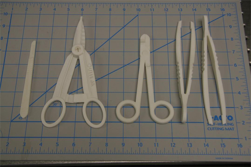
Instruments in the general surgical set are shown in Figure 3.
Figure 3.

Scalpel handle, hemostats, needle drivers, forceps. Scale at bottom is in inches.
Discussion
In this study the authors present a process to design, build and optimize a general surgical set. A series of 5 iterative cycles led to the creation of instruments accepted by a group of physicians as technically able to perform general surgical procedures. This paper explores this process and elaborates on the workflow presented in Figure 2. SLS is a new manufacturing method for general surgical instruments, and several key aspects important to its use were identified in this paper.
DuraForm EX plastic has very different material properties than stainless steel. As described in the results section, many of the modifications were made to address this issue. For example, dimensions perpendicular to the major axes of bending had to be increased to stiffen the handles of the needle driver and hemostat, preventing flex that diminishes applied force at the instrument tips. Moments of inertia for the handles were increased by making the handles disproportionately ‘flatter’ than standard metal instruments, which allowed increased stiffness without unnecessary bulk.
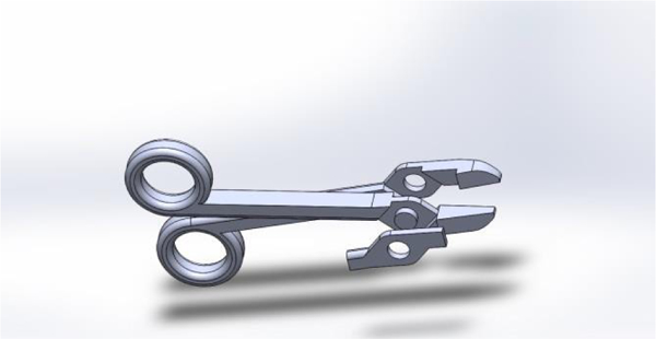
Hinged instruments presented two main design challenges: adequate structural strength and easy assembly. Designing a hinge system with the inherent tradeoff of strength versus size was a focal point for the designers. Shear loading at the hinge occurs when a force load is applied by the handles through the hinge to the tips of the instrument. Apart from ultimate strength limits, the hinge must be appropriately sized to avoid excessive deflection that could cause binding and subsequent difficulty in rotation. Additionally, an oversized hinge would present problems to the user by obstructing his or her view of the instrument tips, or physically preventing the instrument from reaching deep targets. Two hinge systems were used in the general surgical set. A ‘snap-lock’ system was designed and implemented with the hemostats with a recessed central locking stud, surrounded by a large surface area bearing surface. This provided adequate fastening along the axis of the hinge, thereby ensuring alignment of the tips. The bearing surfaces included several ribs and grooves to help maintain concentricity and provide feedback when the two parts have successfully locked together. The needle driver featured a hinge similar to what is used in standard surgical practice, with one arm of the driver embedded in another (Figure 4). Since the tolerance of the SLS printer is not fine enough, the instrument was built in three different pieces and assembled through a one step process requiring epoxy. Furthermore, any prospective 3D printer to be used for this application must maintain sufficiently small dimensional tolerances, approximately 0.01 inches, to ensure good form and fit of any hinge. A printer with poor resolution or tolerances may produce parts that will not mate properly, or be too loose to perform delicate tasks.
Figure 4.

Digital rendering of the needle driver, exploded into its three parts.
A major objective in this study was to build instruments that required little to no post processing and no special tools for final assembly. Virtually all 3D printed parts require post-processing. The SLS machine specifically requires fine tools and brushes to remove gross excess powder, a bead blaster for fine removal of powder and compressed air for part cleaning. Other 3D printing methods such as FDM require fewer steps to break out parts; many only need a hot water bath containing an alkaline solution to remove supporting structures. In the general surgical set, the scalpel handle, forceps and Army Navy were ready for use out of the build. The hemostat assembly was one step consisting of snapping the two arms together. The needle driver required epoxy to assemble the three part instrument seen in Figure 4.
Finished SLS parts have a porous texture to them, and can be cured to create a fully solid part. Un-infiltrated parts tend to absorb surrounding fluids and stain easily. The instruments used in this study were not sealed. It was noted that these instruments absorbed fluids they came into contact with during the cadaveric surgical procedures.
Conclusions
The advantages of functional 3D printed surgical instruments are enormous. Time constraints on design and instrument production are minimal while physician customization allowed is limitless. The speed of iteration allows next day improvements to the core design of surgical instruments. Furthermore, variations of simple tools like a needle driver or hemostat can be modified based on operative technique demands to optimize function. Future applications include installment of 3D printers where surgical equipment is not readily available, such as forward operating surgical hospitals in combat zones, spacecraft or third world environments. These environments would be supported by on site 3D printers and have access to digital libraries of medical and non-medical parts. The ideal print material still needs to be determined. Further evaluation is needed to find a material which can be printed without additional processing and readily sterilized for surgical use.
Design iteration of the general surgical set will continue. Future design modifications will also investigate the anisotropic effects of build orientation on functionality of the surgical instruments.
Figure 1.

An SLS machine.
References
- 1.Hull CW “Apparatus for production of three-dimensional objects by stereolithography.” U.S. Patent 4,575,330, March 11, 1986.
- 2.Crump SS “Apparatus and method for creating three-dimensional objects.” U.S. Patent 5,121,329, June 9, 1992.
- 3.Beaman JJ; Deckard CR “Selective laser sintering with assisted powder handling.” U.S. Patent 4,938,816, July 3, 1990.
- 4.Berry Connell, Craven Brown. “Preliminary experience with medical applications of rapid prototyping by selective laser sintering” Med Eng Phys. 1997. January;19(1):90–6. [DOI] [PubMed] [Google Scholar]
- 5.Rosset A, Spadola L, and Ratib O, “OsiriX: an open-source software for navigating in multidimensional DICOM images,” Journal of Digital Imaging, vol. 17, no. 3, pp. 205–216, 2004. [DOI] [PMC free article] [PubMed] [Google Scholar]
- 6.Uygun BE. “Organ reengineering through development of a transplantable recellularized liver graft using decellularized liver matrix” Nature Medicine, 16 (7) (2010), pp. 814–820. [DOI] [PMC free article] [PubMed] [Google Scholar]
- 7.Petersen TH, TH. “Tissue-engineered lungs for in vivo implantation.” Science, 329 (5991) (2010), pp. 538–541 [DOI] [PMC free article] [PubMed] [Google Scholar]
- 8.Leukers B “Hydroxyapatite scaffolds for bone tissue engineering made by 3D printing.” Journal of Materials Science: Materials in Medicine 16 (2005) 1121–1124. [DOI] [PubMed] [Google Scholar]
- 9.Solar P, Ulm C, Imhof H et al. , “Precision of threedimensional CT-assisted model production in the maxillofacial area,” European Journal of Radiology, vol. 2, no. 5, pp. 473–477, 1992. [Google Scholar]
- 10.Mavili ME, Canter HI, Saglam-Aydinatay B, Kamaci S, and Kocadereli I, “Use of three- dimensional medical modeling methods for precise planning of orthognathic surgery,” Journal of Craniofacial Surgery, vol. 18, no. 4, pp. 740–747, 2007. [DOI] [PubMed] [Google Scholar]
- 11.Meehan M, Teschner M, and Girod S, “Three-dimensional simulation and prediction of craniofacial surgery,” Orthodontics & Craniofacial Research, vol. 6, supplement 1, pp. 102–107,2003. [DOI] [PubMed] [Google Scholar]
- 12.Silva DN. “Dimensional error in selective laser sintering and 3D-printing of models for craniomaxillary anatomy reconstruction.” J Craniomaxillofac Surg. 2008. December;36(8):443–9. [DOI] [PubMed] [Google Scholar]
- 13.Flugge TV. “Three-Dimensional Plotting and Printing of an Implant Drilling Guide: Simplifying Guided Implant Surgery.” Volume 71, Issue 8, August 2013, Pages 1340–1346. [DOI] [PubMed] [Google Scholar]
- 14.Kondor S “On Demand Additive Manufacturing of a Basic Surgical Kit.” Journal of Medical Devices, ASME September 2013, Vol. 7. [Google Scholar]
- 15.Kondor S “Personalized surgical instruments.” Journal of Medical Devices, ASME September 2013, Vol. 7. [Google Scholar]


