Abstract
In vivo cardiac microstructure acquired using cardiac diffusion tensor imaging (cDTI) is a critical component of patient-specific models of cardiac electrophysiology and mechanics. In order to limit bulk motion artifacts and acquisition time, cDTI microstructural data is acquired at a single cardiac phase necessitating registration to the reference configuration on which the patient-specific computational models are based. Herein, we propose a method to register subject-specific microstructural data to an arbitrary cardiac phase using measured cardiac displacements. We validate our approach using a subject-specific computational phantom based on data from human subjects. Compared to a geometry-based non-rigid registration method, the displacement-based registration leads to improved accuracy (less than 1° versus 10° average median error in cardiomyocyte angular differences) and tighter confidence interval (3° versus 65° average upper limit of the 95% confidence interval).
Index Terms: Cardiac Diffusion Tensor Imaging, Non-rigid Registration, Displacement MRI, Computational Cardiac Phantom
1. INTRODUCTION
Cardiac diffusion tensor imaging (cDTI) is a magnetic resonance imaging (MRI) technique that non-invasively measures the self-diffusion tensor of water in the in vivo beating heart and provides substantial quantitative insight to the heart’s microstructural organization. cDTI measures a symmetric rank-2 diffusion tensor (D) from which an eigensystem decomposition produces three (i = [1, 2, 3]) preferential directions (eigenvectors, e⃗i) and corresponding rates of diffusion (eigenvalues, λi). The correspondence of e⃗i to the microstructural axes of the myocardium has been confirmed by histology [1]. In particular, e⃗1 corresponds to the local cardiomyocyte orientation, e⃗2 corresponds to the within-sheet cross-fiber direction, and e⃗3 corresponds to the sheet-normal direction.
The emergence of in vivo cDTI has already shown significant clinical value in characterizing pathological changes in cardiac microstructure [2, 3]. In addition, in vivo cDTI can now be used to provide patient-specific microstructural data to anchor evaluation of cardiac function [4] and electrophysiology [5].
Current in vivo cDTI methods, however, typically acquire data at a single cardiac phase due to: 1) the long scan times (~2–5 minutes for single-phase and single-slice); and 2) the susceptibility to bulk motion signal corruption during some cardiac phases [6, 7]. The cDTI imaging phase is chosen primarily to obtain the optimal in vivo cDTI data quality, but this cardiac phase does not necessarily correspond to the reference configuration from which patient-specific computational mechanics and electrophysiology models are built. Therefore, the measured microstructural data (e.g., e⃗1) need to be registered to the models’ reference configuration.
The preferred method for registering cardiac microstructure from one cardiac phase (e.g., mid-systolic imaging phase) to another phase (e.g., end-diastolic reference configuration) is not currently established. Current diffusion tensor registration techniques have been primarily developed in the context of co-registering static brain tissue from different datasets [8]. Consequently, the established techniques are concerned with registering corresponding features in each image and do not necessarily incorporate all components of in vivo tissue motion. It remains unclear whether traditional feature-based, non-rigid (NR) tensor registration accurately reorients through-phase cDTI cardiomyocyte orientations in the beating heart. Our goal was to define a framework for using time resolved cardiac displacements acquired using Displacement ENcoding with Stimulated Echoes (DENSE) [9] to register cardiomyocyte orientation vectors (e⃗1) at different cardiac phases.
Herein, the proposed displacement-based registration technique was validated against ground truth in vivo cDTI data deformed using a computational phantom that was designed to reproduce previously reported cardiac motion and the corresponding cardiomyocyte kinematics. To quantify the benefit of a tissue displacement-based approach, we compare its accuracy and precision with an NR tensor registration algorithm based on the left ventricle short axis geometry imaged at each cardiac phase.
2. METHODS
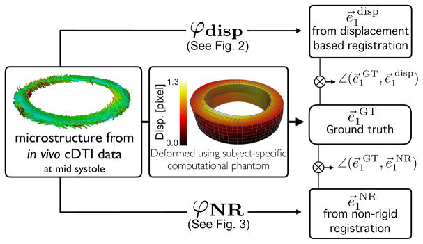
Cardiomyocyte orientations at mid-systole were obtained using in vivo cDTI and re-oriented through the cardiac cycle using a left ventricular computational phantom (LVCP). Since multi-phase cDTI is not currently feasible due to motion corruption and prolonged scan times, the LVCP displacements and cardiomyocyte kinematics were used as ground truth to evaluate the accuracy and precision of the displacement-based registration (Fig. 1). Results were compared to an existing NR geometry-based registration technique.
Fig. 1.
Pipeline. In vivo cDTI-based cardiomyocyte orientations are deformed using the LVCP to obtain ground truth displacements and cardiomyocyte orientation e⃗1GT at different cardiac phases (center). Displacement-based (top, see also Fig. 2) and geometry-based NR (bottom, see also Fig. 3) methods are applied to compute registered cardiomyocyte orientation e⃗1 disp and e⃗1NR, respectively. Angle differences between (e⃗1GT, e⃗1 disp) and (e⃗1GT, e⃗1NR) are computed to evaluate accuracy and precision.
2.1. Image Acquisition
Healthy human subjects (N = 3) were imaged after obtaining informed consent under an IRB approved protocol. Mid-ventricular short-axis cDTI and DENSE MRI data were acquired at 3T (Prisma, Siemens). All data acquisition used navigator triggered free breathing. cDTI was acquired at mid-systole using CODE [6] cDTI: 2×2×5 mm, TE/TR = 74/4000 ms, b-value = 0, 350 s/mm2, Navg = 10, Ndir = 12, Tscan = 4 min. DENSE was acquired at ≈ 60 cardiac phases (15 ms view shared temporal resolution): balanced 4-point encoding in x, y, z, spatial resolution 2.5×2.5×8 mm, TE/TR = 1.04/15, ke = 0.06 cycles/mm, Navg = 3, spiral interleaves = 10, Tscan ≈ 5 min. DENSE images were acquired at the location of the cDTI slice, 8 mm above it, and 8 mm below it.
2.2. Left Ventricular Computational Phantom (LVCP)
A subject-specific LVCP was constructed to evaluate the displacement-based and NR registration approaches. Using the tool described in Spottiswoode et al. [10], three mid-ventricular short axis DENSE magnitude images were segmented and the resulting endocardial and epicardial splines were interpolated with a surface. The enclosed volume was meshed with linear hexahedral finite elements and a boundary value problem was solved to simulate the motion from mid-systole (MS) to end diastole (ED) (Fig. 1, middle). The LVCP boundary value problem enforces quasi-incompressibility of the myocardium and aims to achieve preset realistic target strains in the longitudinal and fiber directions. The magnitude of the target cardiac strains was imposed based on the separation between the MS phase where cDTI was acquired and the phase where myofiber orientations were registered (i.e., ED). To ensure that the LVCP exhibited realistic cardiac motion, we computed strains measured along the longitudinal (ELL), circumferential (ECC), and radial (ERR) directions from MS to ED in each subject-specific model (Table 1). Note that positive ELL, positive ECC, and negative ERR correspond to LV filling from MS to ED. Moreover, the strain values are different among volunteers since microstructural data, LV geometry, heart rate – and therefore the relative cardiac phase where cDTI is acquired – are subject-specific.
Table 1.
Target LVCP longitudinal, circumferential, and radial strains (mean ± standard deviation) from MS back to ED for volunteers 1, 2, and 3.
| ELL | ECC | ERR | |
|---|---|---|---|
| S-1 | 0.10 ± 0.001 | 0.06 ± 0.02 | −0.12 ± 0.01 |
| S-2 | 0.17 ± 0.002 | 0.07 ± 0.03 | −0.15 ± 0.02 |
| S-3 | 0.18 ± 0.003 | 0.11 ± 0.05 | −0.17 ± 0.02 |
Cardiomyocyte orientations were incorporated into the model by interpolating the in vivo cDTI data to the quadrature points of the LVCP mesh using a linear tensor interpolation scheme [11]. Subsequently, based on the LVCP deformation mapping, the cardiomyocyte orientations computed from in vivo cDTI data were mapped to obtain ground truth cardiomyocyte orientations at each simulated cardiac phase.
2.3. Displacement-based Registration
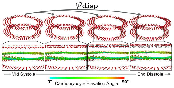
DENSE images acquired above and below the cDTI slice provide 3D Lagrangian displacements ui along the X1, X2, and X3 directions. We use the LVCP to mimic the DENSE displacements and compute ground-truth ui at the location of the finite element nodes a (Fig. 2, top). In our tests, we assumed that the nodes where displacements are known were located at 8mm (as in the current imaging protocol) and at 4mm (simulating DENSE and cDTI staggered images) distance from the cDTI slice location. We interpolated ui using the mesh-free Local Maximum-Entropy (LME) interpolation scheme [12] and computed the local deformation gradient F at the location Xc as:
| (1) |
where FiJ is the (iJ) component of F, n is the number of nodes at which displacements are known inside a search radius r from Xc, Na is the LME shape function corresponding to node a, Na, J(Xc) is the derivative of Na in the J direction evaluated at Xc, and φai is the component i of the current location of node a. The search radius r at each location Xc is chosen so that n ≥ 20. This guarantees the successful calculation of Na in more than 80% of the cases. At the locations Xc where calculation of Na fails, we compute F(Xc) using a central finite difference scheme and linear displacement interpolation. Using F(Xc), we compute the new direction e⃗1disp along which the cardiomyocyte at Xc is reoriented as:
| (2) |
where e⃗1 represent the original direction of the cardiomyocyte (Fig. 2, bottom). Finally e⃗1disp from eq. (2) is renormalized to be a unit vector.
Fig. 2.
Displacement-based registration. The deformation mapping φdisp at each red point above and below the cDTI slice measures the motion between the cDTI acquisition phase (e.g., MS) and the target cardiac phase (e.g., ED). The corresponding deformation gradient F(eq. 1) is used to register the cardiomyocyte orientation vectors e⃗1 (eq. 2).
2.4. Geometry-Based Non-Rigid Registration
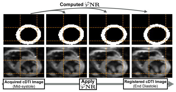
The cDTI data acquired at MS were rotated and translated such that the RV insertion points matched the heart’s configuration in the DENSE image at MS from which the LVCP is built. The tensors were reoriented using the rotation extracted from the computed affine transformation. Once the cDTI heart was aligned with the DENSE configuration at MS, the LV in the cDTI image was segmented and converted to a binary mask. The cDTI LV mask was then elastically deformed using the B-spline registration outlined in Rueckert et al. [13] to match the target DENSE LV masks at each cardiac phase (Fig. 3, top). The binary masks were used to characterize the deformation of the LV from MS to ED as the target for the NR registration. The registration computed from the cDTI and DENSE masks was applied to each diffusion weighted image, thereby deforming the MS cDTI LV data to match the DENSE LV geometry at the chosen cardiac phase (Fig. 3, bottom). Cardiomyocyte orientations e⃗1NR were subsequently computed via eigensystem decomposition of the non-rigidly registered diffusion tensors.
Fig. 3.
Geometry-based NR registration. The deformation mapping φNR is computed to transform the cDTI binary mask to the target cardiac phase. φNR is then applied to each diffusion weighted image and registered cardiomyocyte orientations are recomputed from the non-rigidly registered tensors.
3. RESULTS
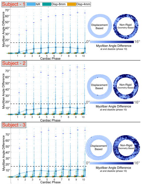
Median angular differences between ground truth and registered cardiomyocytes are smaller if computed using the displacement-based versus the NR approach (average 1° versus 10°). However, both methods result in median angular differences inside the CODE cDTI cone of uncertainty [14] (Fig. 4). Pointwise comparison of the angular differences presents a larger error and a larger confidence interval (CI) if geometry-based NR registration is applied (Fig. 4). The upper limit of the angular difference 95% CI is significantly reduced (average 3° versus 65°) when registration is carried out using the displacement-based versus the geometry-based NR registration (Table 2).
Fig. 4.
Angular differences between ground truth and registered (MS mapped to ED) cardiomyocyte orientation using displacement-based and NR approaches in subject-specific computational phantoms based on N = 3 volunteers. Left: median (square markers) and 95% CI (horizontal tick marks). The dashed line corresponds to the CODE cDTI cone of uncertainty [14]. Right: pointwise registration error at ED.
Table 2.
Median and, in parenthesis, 95% CI of cardiomyocyte angle difference for displacement (φdisp) and geometry-based NR (φNR) registration from MS to ED. φdisp median and 95% CI are reported with displacement information at 8mm and 4mm from cDTI slice.
| φdisp | φNR | ||
|---|---|---|---|
| 8 mm | 4 mm | ||
| S-1 | 0.4° (0.1°–1.7°) | 0.3° (0.1°–0.8°) | 8.8° (1.4°–55.7°) |
| S-2 | 0.8° (0.1°–2.9°) | 0.4° (0.1°–1.6°) | 11.0° (1.6°–73.2°) |
| S-3 | 1.0° (0.1°–9.7°) | 0.6° (0.1°–2.0°) | 10.7° (1.9°–65.7°) |
4. DISCUSSION
The proposed displacement-based registration outperforms the geometry-based NR registration in terms of cardiomyocyte angle accuracy and precision (significantly tighter 95% CI). Improved accuracy and precision may result from the displacement-based approach incorporating all components of cardiac motion – including through plane components –whereas the geometry-based NR registration technique does not account for longitudinal motion and shear strains due to intra-slice torsion. Furthermore, the geometry-based NR registration is applied directly to the diffusion weighted images and it remains unclear how this transformation affects the recomputed diffusion tensors.
Knowing the displacement field at 4mm spacing above and below the cDTI slice and not at 8mm improved accuracy and precision (see Fig. 4 and Table 2). This suggests an adjustment of the imaging protocol: instead of acquiring cDTI and DENSE images at the same locations, cDTI and DENSE images should be interleaved so that their effective distance is half the chosen slice thickness of 8mm.
The error resulting from the geometry-based NR registration is significant across the myocardium. On the contrary, the error computed using the displacement-based method is generally small, except for a limited number of points close to the slice boundaries. The higher error close to the boundaries is likely due to failure of LME shape function to converge and may be addressed with more sophisticated solvers.
The baseline NR registration technique used in this study can be improved to further examine the benefits and drawbacks of a displacement-based approach. Since the healthy LV has a regular annular shape with few tissue heterogeneities, the binary masks of the segmented LV serve as a basic feature tracking registration strategy. A technique that incorporates more features into the algorithm (e.g., papillary muscles, right ventricle insertion points, trabeculae) can be used in future work to improve the NR registration accuracy in capturing myocardial motion.
Our geometry-based NR registration pipeline recomputes D after the applied NR deformation. This results in deforming the domain in which the diffusion tensors are interpolated and in changing the diffusion tensors themselves since the pixel intensity of the registered images is affected by the registration. As a result, the NR algorithm does not accurately rotate D according to the in-plane shearing and stretching. Although the effect from this rotation may be small, other tensor reorientation strategies need to be examined in future work as, for example, the finite strain and preservation of principal direction approaches outlined in Alexander et al. [8].
One of the limitations of the displacement-based approach is the requirement of DENSE images that, if not already acquired for other purposes, will result in longer imaging protocols. Furthermore, the presented approach registers and reorients the cardiomyocytes through the cardiac cycle based on displacement derivatives, i.e., F. In presence of noise, the error in the displacement field may be amplified by calculating F. Although the diffuse domain of the LME shape functions may limit noise amplification, this aspect needs to be carefully investigated in future work.
This work demonstrates an initial validation of a displacement based registration pipeline for cDTI using computationally derived cardiac kinematics. Based on the proposed approach, accurate time resolved cardiomyocyte orientations in the beating heart can be computed from cDTI acquired at a single cardiac phase using displacement encoded MRI. The framework can be expanded to reorient the within-sheet cross-fiber directions (e⃗2) and sheet-normal directions (e⃗3) throughout the cardiac cycle as well. When used entirely with experimental functional and microstructural MRI data, the proposed framework also has the potential to reveal insights into microstructural mechanisms of cardiac dysfunction.
Acknowledgments
The authors gratefully acknowledge NIH R01-HL131823, NIH R01-HL131975, NIH K25-HL135408, and UCLA URSP support.
References
- 1.Scollan DF, Holmes A, Winslow R, Forder J. Histological validation of myocardial microstructure obtained from diffusion tensor magnetic resonance imaging. Am J Physiol-Heart C. 1998;275(6):H2308–H2318. doi: 10.1152/ajpheart.1998.275.6.H2308. [DOI] [PubMed] [Google Scholar]
- 2.Wu MT, Su MYM, Huang YL, Chiou KR, Yang P, Pan HB, Reese TG, Wedeen VJ, Tseng WYI. Sequential changes of myocardial microstructure in patients postmyocardial infarction by diffusion-tensor cardiac MR. Circ-Cardiovasc Imag. 2009;2(1):32–40. doi: 10.1161/CIRCIMAGING.108.778902. [DOI] [PubMed] [Google Scholar]
- 3.Nielles-Vallespin S, Khalique Z, Ferreira PF, de Silva R, Scott AD, Kilner P, McGill LA, Giannakidis A, Gatehouse PD, Ennis D, et al. Assessment of myocardial microstructural dynamics by in vivo diffusion tensor cardiac magnetic resonance. J Am Coll Cardiol. 2017;69(6):661–676. doi: 10.1016/j.jacc.2016.11.051. [DOI] [PMC free article] [PubMed] [Google Scholar]
- 4.Perotti LE, Magrath P, Verzhbinsky IA, Aliotta E, Moulin K, Ennis DB. FIMH conference. Springer; 2017. Microstructurally anchored cardiac kinematics by combining in vivo DENSE MRI and cDTI; pp. 381–391. [DOI] [PMC free article] [PubMed] [Google Scholar]
- 5.Ponnaluri AVS, Perotti LE, Liu M, Qu Z, Weiss JN, Ennis DB, Klug WS, Garfinkel A. Electrophysiology of heart failure using a rabbit model: from the failing myocyte to ventricular fibrillation. PLoS Comput Biol. 2016;12(6):e1004968. doi: 10.1371/journal.pcbi.1004968. [DOI] [PMC free article] [PubMed] [Google Scholar]
- 6.Aliotta E, Wu HH, Ennis DB. Convex optimized diffusion encoding (CODE) gradient waveforms for minimum echo time and bulk motion-compensated diffusion-weighted MRI. Magn Reson Med. 2017;77(2):717–729. doi: 10.1002/mrm.26166. [DOI] [PubMed] [Google Scholar]
- 7.Stoeck CT, Von Deuster C, Genet M, Atkinson D, Kozerke S. Second-order motion-compensated spin echo diffusion tensor imaging of the human heart. Magn Reson Med. 2016;75(4):1669–1676. doi: 10.1002/mrm.25784. [DOI] [PubMed] [Google Scholar]
- 8.Alexander DC, Pierpaoli C, Basser PJ, Gee JC. Spatial transformations of diffusion tensor magnetic resonance images. IEEE T Med Imaging. 2001;20(11):1131–1139. doi: 10.1109/42.963816. [DOI] [PubMed] [Google Scholar]
- 9.Aletras AH, Ding S, Balaban RS, Wen H. DENSE: displacement encoding with stimulated echoes in cardiac functional MRI. J Magn Reson Im. 1999;137(1):247–252. doi: 10.1006/jmre.1998.1676. [DOI] [PMC free article] [PubMed] [Google Scholar]
- 10.Spottiswoode BS, Zhong X, Hess AT, Kramer CM, Meintjes EM, Mayosi BM, Epstein FH. Tracking myocardial motion from cine DENSE images using spatiotemporal phase unwrapping and temporal fitting. IEEE T Med Imaging. 2007;26(1):15–30. doi: 10.1109/TMI.2006.884215. [DOI] [PubMed] [Google Scholar]
- 11.Gahm JK, Wisniewski N, Kindlmann G, Kung GL, Klug WS. MICCAI conference. Springer; 2012. A Garfinkel, and DB Ennis, “Linear invariant tensor interpolation applied to cardiac diffusion tensor MRI; pp. 494–501. [DOI] [PMC free article] [PubMed] [Google Scholar]
- 12.Arroyo M, Ortiz M. Local maximum-entropy approximation schemes: a seamless bridge between finite elements and meshfree methods. Int J Numer Meth Eng. 2006;65(13):2167–2202. [Google Scholar]
- 13.Rueckert D, Sonoda LI, Hayes C, Hill DLG, Leach MO, Hawkes DJ. Nonrigid registration using free-form deformations: application to breast MR images. IEEE T Med Imaging. 1999;18(8):712–721. doi: 10.1109/42.796284. [DOI] [PubMed] [Google Scholar]
- 14.Aliotta E, Moulin K, Magrath P, Ennis DB. Characterizing the cardiac phase dependence of motion compensated CODE cDTI. ISMRM Annual Meeting. 2017 [Google Scholar]


