Abstract
Synthetic mesh for pelvic organ prolapse (POP) repair is associated with high complication rates. While current devices incorporate large pores (>1 mm), recent studies have shown that uniaxial loading of mesh reduces pore size, raising the risk for complications. However, it is difficult to translate uniaxial results to transvaginal meshes, as in vivo loading is multidirectional. Thus, the aim of this study was to (1) experimentally characterize deformation of pore diameters in a transvaginal mesh in response to clinically relevant multidirectional loading and (2) develop a computational model to simulate mesh behavior in response to in vivo loading conditions. Tension (2.5 N) was applied to each of mesh arm to simulate surgical implantation. Two loading conditions were assessed where the angle of the applied tension was altered and image analysis was used to quantify changes in pore dimensions. A computational model was developed and used to simulate pore behavior in response to these same loading conditions and the results were compared to experimental findings. For both conditions, between 26.4% and 56.6% of all pores were found to have diameters <1 mm. Significant reductions in pore diameter were noted in the inferior arms and between the two superior arms. The computational model identified the same regions, though the model generally underestimated pore deformation. This study demonstrates that multiaxial loading applied clinically has the potential to locally reduce porosity in transvaginal mesh, increasing the risk for complications. Computational simulations show potential of predicting this behavior for more complex loading conditions.
Keywords: transvaginal mesh, complications, pelvic organ prolapse, pore diameter, finite element
1. Introduction
Each year ∼300,000 women in the U.S. undergo surgical repair for pelvic organ prolapse (POP), a pelvic floor disorder characterized by the descent of the pelvic organs into the vaginal canal. In one-third of all surgical repairs for POP, synthetic mesh is used to restore support to the pelvic organs [1]. Despite improved anatomical outcomes relative to native tissue repairs, the efficacy of synthetic mesh has been questioned due to high rates of complications, ranging from 15% to 20% [2,3]. When used to treat POP, synthetic mesh functions as a load bearing structure, maintaining a patient's anatomy as the pelvic organs experience physiological loads. Despite this function, the in vivo mechanical behavior of synthetic mesh is largely unknown, as is the impact of its mechanics on surrounding biological tissues.
Recently, the textile and structural properties of mesh have become an area of intense interest with many recent publications and vendors touting superior porosity and mechanical strength of their products [4–6]. The importance of textile properties has been well documented in hernia mesh literature, where pore size was found to have a dramatic impact on the host response. Specifically, pores less than 1 mm in diameter were found to result in inferior mesh-tissue integration and caused an increased host inflammatory response [7–9]. While these studies were conducted in the abdominal wall, vaginal mesh products are largely constructed using the same textile methods and materials, as vaginal mesh technology is predicated on hernia mesh devices. Still, recent studies have found that pelvic floor applications of mesh appear to be more vulnerable to mesh related complications relative to the abdominal applications [10], suggesting the impact of pore sizes less than 1 mm may be exacerbated when mesh is used for pelvic organ prolapse repair.
Though nearly all contemporary vaginal mesh devices are constructed with pores greater than 1 mm in diameter, it has recently been shown that mechanical loading significantly alters pore dimensions. In fact, physiological levels of uniaxial force have been found to deform pores in a rectangular strip of mesh such that pore diameters fell well below 1 mm and mesh porosity was reduced to ∼0% [11]. Such deformation indicates that mesh devices with large pores (>1 mm) may be unacceptable following implantation as surgical tensioning and in vivo loading may drastically reduce pore diameters. Although previous work has quantified the reduction in porosity and pore diameter in response to mechanical loading, these experiments only considered uniaxial loading of rectangular strips of mesh [11]. While uniaxial loading of rectangular samples is relevant to vaginal mesh used for abdominal sacrocolpopexy, devices used for transvaginal mesh surgeries often exhibit more complex geometries and experience complex multidirectional loading in vivo. Thus, it is difficult to translate the findings from uniaxial experiments to these devices.
Typically, transvaginal meshes have two to four “arms” extending from the main body of the mesh. The mesh body is fixed to the vagina via sutures, while the arms are pulled through various anatomical landmarks in the pelvic sidewall and pulled taught (“tensioned”). This multiaxial loading condition likely results in complex force distribution across the device creating nonhomogeneous pore deformations throughout the device.
In order to examine the complex geometry and loading of transvaginal mesh, the aims of this study were to (1) develop an experimental model to load and quantify pore dimensions of transvaginal mesh in response to clinically relevant mechanical loads and (2) develop a computational model to simulate the mechanical behavior of transvaginal mesh in response to clinically relevant mechanical loads. We hypothesize that transvaginal mesh will deform such that the number of pores with diameters less than 1 mm will increase relative to its undeformed configuration in response to tensile loads representative of those applied during implantation. While the experimental model will provide insight into the mechanics of transvaginal mesh, developing an accompanying computational model allows for a wide range of loading conditions to be examined, providing a tool that can be used to further understand mesh mechanics and optimize mesh products for the mechanical environment of the female pelvic floor.
2. Methods
2.1. Experimental Testing.
In this study, a transvaginal mesh product, DirectFix A (Coloplast, Minneapolis, MN), was used for experimental testing. DirectFix A was chosen as this device was in clinical use at the time of this study and is directly cut from a sheet of Restorelle™, a mesh with a relatively simple square pore geometry. This simple pore geometry is utilized across a number of other mesh devices produced by several manufacturers. For experimental testing, a custom apparatus was designed and machined to simultaneously load all four arms of the transvaginal mesh (Fig. 1). The testing rig consisted of a raised platform centered within a series of cylindrical pegs (5 mm diameter) arranged in a circular pattern. Pegs were placed in 5 deg increments at a distance of 5 in from the platform center. In addition, four detachable posts with rounded tops were constructed and could be installed onto any of the 72 peg locations.
Fig. 1.
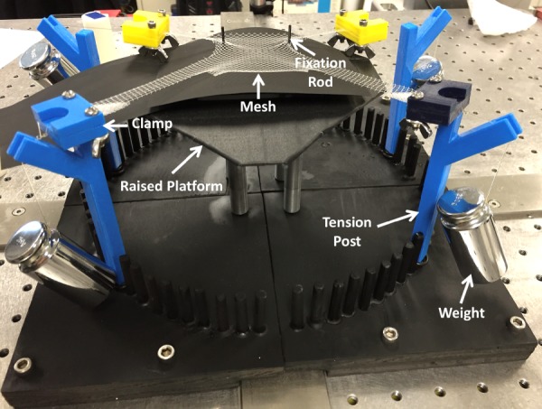
Experimental loading of DirectFix A using a custom testing rig. Mesh arms were placed in custom clamps and a 250 g weight was allowed to hang freely from tension posts as shown. In addition, two fixation rods located on a raised platform were placed through individual pores in the mesh body.
During testing, each mesh sample was centered on the raised platform, and two steel rods (∼1 mm in diameter) were placed through separate mesh pores on the inferior body of the device to prevent translation of the mesh, mimicking suture fixation to the vagina (Fig. 1). In order to apply loads, the most distal 5 mm of each arm was placed in a soft tissue clamp and a suture line was used to attach a 250 g weight to each clamp. Tension (∼2.45 N) was applied to each mesh arm by placing the suture lines on the rounded posts and allowing the weights to hang freely. For undeformed trials (0 N tension), no weights were applied.
For each sample, the mesh was centered on the platform, located with the fixation rods, and the entire mesh was imaged in an undeformed configuration (0 N). After the undeformed image was captured, a clamp was attached to each arm and the weights were suspended over the posts in one of two loading scenarios: (1) the top arms were loaded at 40 deg and the bottom arms were loaded at −20 deg (n = 3, Fig. 2) and (2) the top arms were loaded at 10 deg and the bottom arms were loaded at −45 deg (n = 3, Fig. 2). All angles were relative to the horizontal axis, with the origin at the device/platform center. The load and angles were chosen to represent surgical positioning of the mesh based on three-dimensional (3D) reconstruction of various patient anatomies and the load-elongation behavior of Restorelle [11], neglecting out of plane tensioning. An image of the deformed mesh was captured after all four weights were freely hanging. All images were captured using a digital SLR camera (Canon, EOS Rebel T3, Melville, NY) equipped with a 18 mm lens (Canon, EFS f/2.8, Melville, NY), fixed above the testing platform, parallel to the mesh surface.
Fig. 2.
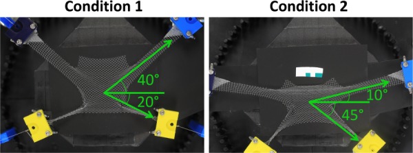
For experimental testing, two separate loading conditions were considered. Under the first condition, upper arms were loaded at 40 deg and the lower arms were loaded at −20 deg. For condition 2, upper arms were loaded at 10 deg, while lower arms were loaded at −45 deg. All angles are relative to the horizontal axis, with the origin at the device center. A weight of 250 g was applied to each mesh arm at the prescribed angle via soft tissue clamps.
2.2. Computational Testing.
A computational geometry of DirectFix A was created in Solidworks (V.2013, Dassault Systèmes, Waltham, MA), using a Boolean subtraction to cut the contour of the transvaginal mesh from a 100 × 100 cm sheet of Restorelle (square pores with diameter = 2.0 mm, Fig. 3). The Solidworks geometry was then imported into Autodesk Simulation Mechanical 2014–2015 (Autodesk, San Rafael, CA) and discretized with hexahedral elements. To mimic the construction of mesh textiles and address observations of fiber recruitment, pore size reduction, and the nonlinear load-elongation behavior of textile mesh [11], the computational model was divided into two components, fibers and knots (Fig. 3). Here, the fibers are the primary load-bearing component, while the knots are the intersection of fibers and serve as pivot points that compress, allowing fibers to rotate in response to applied loads. The fibers and knots were considered distinct Neo-Hookean materials (E = Young's modulus and ν = Poisson's ratio) and material properties were determined using an inverse optimization routine in FEBio (University of Utah, MRL), with data obtained from uniaxial tensile testing of Restorelle™. Uniaxial testing of Restorelle was conducted with the mesh in two distinct orientations; the primary fibers oriented at 0 deg relative to the horizontal and the primary fibers oriented at 45 deg relative to the horizontal (n = 5 each, Fig. 4). Optimized material properties for the fibers (Efiber = ∼5000 MPa, νfiber = ∼0.49) and knots (Eknot = ∼100 MPa, νknot = ∼0.01) were used for all simulations.
Fig. 3.
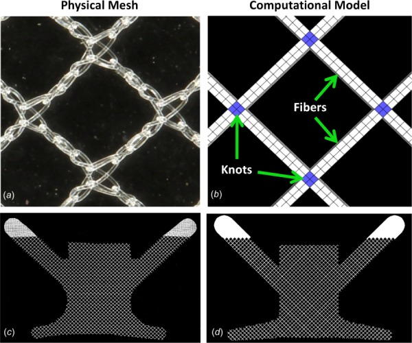
In order to model the mesh microstructure, the physical pore geometry (a) was simplified and the computational pore geometry (b) was constructed from a network of fiber (light) and knot (dark) structures. Here, the primary fibers are oriented at 45 deg relative to the horizontal ((a) and (b)). To recreate the gross geometry of DirectFix A (c), the computational model (d) was cut from the repeating pattern of the pore geometry in SOLIDWORKS.
Fig. 4.
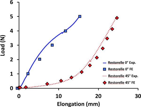
Young's modulus and Poisson's ratio for both the knot and fiber materials. Solid and dashed lines are representative experimental uniaxial load-elongation data for Restorelle tested with fibers 0 deg and 45 deg offset, respectively. Square and diamond symbols indicate are load-elongation data points from corresponding finite element simulations (0 deg and 45 deg orientations) with the calibrated model.
The discretized model was then imported into Preview (University of Utah, MRL) and the experimental conditions described above were recreated. The DirectFix A geometry was centered about the origin of the computational axis and a traction vector with a magnitude of 2.45 N was applied to the nodes of the most distal 10 mm of the mesh arms, where the x and y components of the traction vector were adjusted to provide the correct angle of loading for a given scenario. Due to computational difficulties, contact between the mesh and the fixation rods was not considered. Rather, the interior surface of the pore surrounding each fixation rod was rigidly fixed (translation = rotation = 0). Removal of this contact greatly improved convergence and performance of the computational simulation. Last, a sliding contact was prescribed for all mesh surfaces to prevent penetration of mesh fibers and knots. Similar to experimental testing, an image of the undeformed and deformed geometries was obtained for each condition.
2.3. Mesh Burden.
To examine the deformation of DirectFix A, mesh burden and pore diameter were determined for all undeformed and deformed images. Mesh burden is a term used in this study that refers to the area density of mesh in units of pixels per mm2. Thus, a higher area density of the mesh, i.e., mesh burden, places more material in contact with the vagina, thereby increasing the likelihood of a more significant foreign body reaction, hence the choice of the term “burden.” Here, it is assumed that mesh deformation is planar with the amount of mesh in undeformed and deformed images remaining constant, though the distribution (area density) may change. Prior to the determination of mesh burden, all images were binarized such that pixels representing the mesh were black and pixels representing void space (no mesh) were white. For each pixel representing mesh, the total number of mesh pixels within a radius of 2 mm was determined, providing a local density (pixels/mm2) value for each pixel. A radius of 2 mm was chosen as it provides a nonzero baseline measure of mesh burden for Restorelle and was the value measured for the undeformed pore diameter. Mesh burden values for the deformed geometries were normalized by the maximum mesh burden in the corresponding undeformed configuration, providing a measure of the change in mesh burden following the application of load. This normalization was required as computational and experimental images had differing image resolutions. Without normalization, higher resolution images resulted in greater mesh burden values relative to lower resolution images. After calculating normalized mesh burden for each pixel, results were visualized using 2D contour plots.
2.4. Minimum Pore Diameter.
The method used to measure minimum pore diameter, dmin, has previously been described [11]. Briefly, images were scaled using the dimensions of the undeformed geometry and binarized to distinguish whether pixels represented mesh or void space. Clusters of void space were identified as pores and the center of mass for each pore was then determined (Fig. 5). Finally, a series of diameters were determined for each pore, where each pore diameter was required to pass through the pore centroid. The minimum diameter (dmin) was then recorded for each pore. In addition, the total number of pores less than 1 mm was determined for all undeformed and deformed images.
Fig. 5.
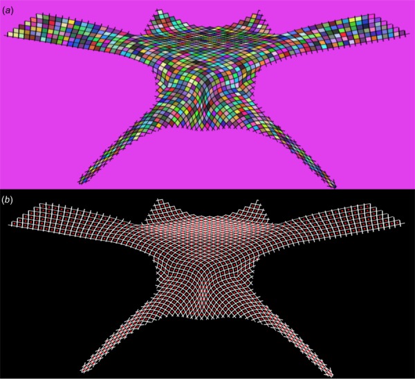
Image processing was used to automatically identify mesh pores and determine their minimum diameters. First, a gradient based method was used to identify isolated clusters, representing pores. Here, each shaded cell represents a cluster of pixels identified as a pore (a). Next, the centroid of each cluster was determined (represented by individual dots) and used to determine the minimum diameter for each pore (b).
2.5. Convergence Testing.
For each boundary condition, model convergence (refinement of the finite element (FE) “mesh” or h-refinement) was examined considering the values of normalized mesh burden and dmin. In this study three levels of h-refinement were considered with mesh geometries consisting of 29,066, 136,349, and 232,646 linear hexahedral elements. Average normalized mesh burden and dmin values were found to converge quickly with standard deviations less than 2% across all three models, regardless of the boundary conditions examined. Given the minimal sensitivity of the output variables to the number of elements used, all values reported in this study were obtained using the 136,349 element geometry.
2.6. Statistics.
Statistical analysis was performed for both mesh burden and dmin measurements to compare the undeformed and deformed geometries for each sample using SPSS (V20, IBM, Armonk, NY) with a significance of p < 0.05. In order to compare the overall mesh deformation, the average values of mesh burden and pore diameter were calculated for both the undeformed and deformed geometries. The impact of loading on average dmin was examined using a Kruskal–Wallis test. In addition, a Bland–Altman analysis was used to compare differences between experimental and FE results for each loading condition.
3. Results
3.1. Experimental Results.
In response to loading condition 1, DirectFix A experienced significant pore deformation with the most dramatic increases in mesh burden observed in the inferior mesh arms, around the fixation rods, and within the mesh body between the superior mesh arms (Fig. 6). Although few pores were found to have a diameter less than 1 mm in the undeformed state, 26.4% of all pores were found to have diameters less than 1 mm upon application of force (p < 0.05). This dramatic deformation resulted in a substantial decrease in mean pore diameter for the entire mesh, falling from 1.99 mm in the unloaded state to 1.34 mm with load applied (Table 1). The distribution of normalized mesh burden was consistent with experimental observations, as peak values of normalized mesh burden were located in the proximal portion of the inferior arms, approaching the fixation rods. Here, mesh burden was increased by ∼260%, relative to the unloaded device (260% increase in mesh per unit area, Fig. 6). Similarly, the superior mesh body, between the arms, experienced ∼190% increase in mesh burden for condition 1.
Fig. 6.
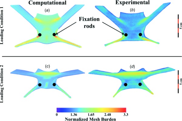
Contour plots of normalized mesh burden for deformed DirectFix A geometries. Overall, computational and experimental results demonstrate good agreement for loading condition 1 (top) and 2 (bottom). Mesh burden values were normalized by the maximum mesh burden of the undeformed geometry. Warmer colors represent greater percent increases in mesh concentration.
Table 1.
Summary of pore deformation for experimental and computational testing of condition 1 and condition 2 with 0 N (no load) or 2.45 N (loaded) applied to each arm. The value for the total number of pores was obtained using images of the undeformed DirectFix A geometry. Mean pore diameter was obtained from averaging all dmin values obtained from a single image. Note computational models provide a single value obtained from the converged model.
| Total number pores | Number of pores <1 mm (no load) | Number of pores <1 mm (load) | Mean pore diameter with no load (mm) | Mean pore diameter when loaded (mm) | |
|---|---|---|---|---|---|
| Condition 1—experimental | 1095 ± 17 | 7 ± 12 | 289 ± 39 | 2.02 ± 0.02 | 1.34 ± 0.12 |
| Condition 1—computational | 1052 | 0 | 324 | 2.25 | 1.66 |
| Condition 2—experimental | 1206 ± 11 | 0 ± 0 | 682 ± 56 | 1.99 ± 0.02 | 1.03 ± 0.02 |
| Condition 2—computational | 1045 | 0 | 153 | 2.24 | 1.68 |
Condition 2 resulted in more widespread pore deformation, impacting a larger percentage of the DirectFix A geometry. For condition 2, no pores were found to have a diameter less than 1 mm in the undeformed state, though upon loading 56.6% of all pores were found to have diameters less than 1 mm (p < 0.05). This pore deformation was found to decrease the mean pore diameter of the entire mesh from 2.02 mm to 1.03 mm (Table 1, p < 0.05). Whereas increased mesh burden for condition 1 was concentrated immediately inferior-lateral to the fixation rods and extended into the lower mesh arms, condition 2 resulted in a widespread increase in mesh burden between the superior mesh arms, with decreases in pore size extending into the superior arms themselves. Across the superior region of the device, mesh burden was fairly uniform with increases of ∼236%, relative to the unloaded device. Similar to condition 1, condition 2 resulted in a dramatic reduction of pore size in the inferior mesh arms, with increases in mesh burden of ∼200% relative to the unloaded device.
3.3. Computational Model.
Overall, the computational simulations captured the deformation of DirectFix A that was observed experimentally (Fig. 6). For condition 1, the most dramatic deformations were found in the inferior mesh arms, around the fixation rods, and the mesh body between the superior mesh arms. However, greater normalized mesh burden values were obtained via FE simulations for condition 1, with a peak increase of 330% at the fixation rods (Fig. 6, p < 0.05). Predicted increases in mesh burden at the inferior mesh arms and the superior mesh body were similar between experimental and computational models, with approximately a two-fold increase at these locations (p > 0.05). Locations of decreased dmin showed good agreement with regions of increased mesh burden, demonstrating the inverse correlation between these parameters (decrease in diameter results in increase mesh per unit area). Median dmin values were similar between FE predictions and experimental findings for condition 1, with just a 0.1% and 9% difference for undeformed and deformed geometries, respectively (Fig. 7).
Fig. 7.
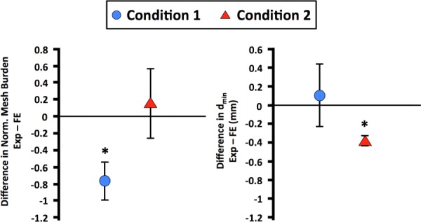
Bland–Altman plots for average normalized mesh burden (left) and dmin (right). The y-axis represents the difference between experimental and finite element results. Condition 1 is represented by the circular symbols and condition 2 is represented by the triangular symbols. Error bars represent standard deviation. * represents significant differences between experimental and finite element measurements (p < 0.05).
Overall, the FE simulation for condition 2 demonstrated good agreement with experimental observations, with notable mesh deformation in the inferior arms and between the superior mesh arms. A maximum increase in mesh burden was found between the superior arms, with an increase of ∼221%, similar to that determined experimentally (p > 0.05). However, the computational model was unable to capture the magnitude of the decrease in pore diameter, with dmin values significantly greater than those obtained experimentally (p < 0.05, Table 1).
4. Discussion
In this study, the deformation of a transvaginal prolapse mesh, DirectFix A, was examined in response to two clinically relevant loading conditions. In addition, a computational model for DirectFix A was developed and its deformation behavior was compared with experimental findings. Both experimental and computational results found that multiaxial tensile loading of DirectFix A results in a significant reduction of pore size, with regions of increased mesh burden relative to the unloaded geometry. Despite containing ∼0 pores with diameters less than 1 mm prior to loading, the application of multiaxial tension reduced pore diameter to less than 1 mm for a hundreds of pores across the mesh device considered. While the computational model of DirectFix A produced similar behavior to that observed experimentally, the current computational implementation was unable to capture the magnitude of pore collapse, generally over predicting pore diameter. Nonetheless the current computational model provides a conservative method for evaluating the behavior of complex mesh geometries and predicting areas at risk for increases in mesh burden for the transvaginal mesh device examined.
Importantly, this study has demonstrated that transvaginal mesh devices are highly susceptible to pore collapse in response to clinically relevant multiaxial tensile loads. The present findings are in agreement with those observed previously for rectangular strips of mesh [11]. This is largely due to the manner in which the filaments used to construct mesh distribute force. Specifically, mesh filaments rotate and orient in the direction of the applied load, distorting the unloaded pore geometry. Though stiffer filaments or mesh construction techniques that minimize the rotation of filaments can be used to eliminate or reduce deformation, such construction would create a stiff, nonpliable mesh structure that may not conform to the shape of biological structures. In addition, stiff mesh structures have been shown to also induce a negative host response [12]. Regardless of mesh stiffness, this study illustrates that regions of increased mesh burden are likely to occur along lines of force transmission in vaginal mesh. Clinical consideration of this concept may allow for mesh geometries and surgical techniques, specifically placement of fixation sites, to be optimized in order to reduce or eliminate unwanted pore deformation.
Notably, both experimental and computational results identified two regions of dramatic increases in mesh burden, regardless of the boundary condition: the inferior (distal) mesh arms and mesh body between the superior arms. While the inferior mesh arms are typically not in contact with the vagina, the superior mesh body is placed directly on the anterior vagina. Therefore, reduced pore dimensions in this location may greatly impact the host response and subsequent integration of mesh with the anterior vagina or increase the risk of mesh related complications in this region of the vagina. Indeed, this finding is in agreement with clinical observations of pain and exposure, as the mesh body between the superior arms is widely recognized as a site of tenderness, pain, and mesh exposure [13]. Clinicians have even reported the ability to transvaginally palpate a taut band between the superior mesh arms during postsurgical exams [14]. A study by Feiner and Maher further highlights this region and the authors include sketches of pain locations that are strikingly similar to the contour plots of mesh burden presented in Fig. 6 of the current study [13]. The correspondence with observations by Feiner and Maher provides additional supportive evidence that the decrease in pore size resulting from mechanical loading is a mechanism by which transvaginal mesh complications can occur.
While the overall deformation of the computational model was similar to experimental measurements for DirectFix A, it was noted that the model was unable to capture the degree of pore reduction observed experimentally. In addition, it was noted that the computational model tended to overestimate mesh burden. This difference between the computational and experimental observations likely arises from the fact that the computational mesh was limited to planar (2D) deformation, while experimental testing was observed to deform out of plane. Specifically, buckling or winkling, was noted during experimental testing of mesh samples in the vicinity of the fixation rods. Though out of plane deformation could not be quantified by the experimental methods employed here (planar photography), images of the mesh before and after loading were compared in order to determine the relative amount of mesh that had moved out of plane or became “hidden” as a result of filaments passing behind other filaments. This was accomplished by comparing the number of pixels representing “mesh” in each image and comparing the undeformed and deformed states for each sample.
For loading condition 1 the number of pixels representing mesh material decreased by ∼24% in the loaded state, relative to the unloaded state. Similarly, a ∼10% decrease was observed for loading condition 2. These differences indicate that less mesh material was observable in the images of the “loaded” state, and as such it is not surprising that experimental mesh burden measurements were lower relative to computational predictions. Given this observation, it is likely that experimental values for mesh burden are underestimates since out of plane deformation, such as wrinkling, provides an additional mechanism by which mesh burden can increase in 3D (increased amount of mesh per unit volume).
Although the computational model here does not capture the out of plane deformation observed experimentally, it provides an idealistic model of mesh deformation in two dimensions. Remarkably this provided the ability to capture the same behavioral trends as those observed experimentally and indicate areas of undesired mesh deformation. Therefore, the current model can potentially be used to examine a much wider range of loading conditions for a given mesh and identify which loading scenarios are at high risk for increases in mesh burden. This approach can provide a tremendous clinical benefit, allowing surgeons or mesh manufacturers to identify an ideal mesh geometry for the mechanical environment of the pelvic floor or at minimum identifying suturing locations to reduce pore collapse and increases in mesh burden. The true potential of a computational model of transvaginal mesh may be realized when combined with patient specific geometries and loading conditions obtained from magnetic resonance imaging or computed tomography reconstructions. These computational tools would greatly enhance surgical planning and would provide improved design criteria for mesh manufacturers. Similar patient specific computational methods have previously been used to understand and create surgical plans for orthopedic and ophthalmology disorders [15–17].
Clinically, it should be noted that this study provides a time-zero perspective of mesh deformation in response to loading. As such, the impact of tissue boundaries, tissue integration, and additional biological factors are neglected. Still this study demonstrates that the method of mesh fixation, in addition to the magnitude and direction in which tension is applied to a mesh, directly alters the configuration of mesh pores and likely the immune response. Therefore, mesh manufacturers and surgeons must consider boundary conditions such as the location and number of fixation points used, as well as the force applied to tension the mesh. Importantly, it should be noted that this study considers a single transvaginal mesh device under two specific loading conditions. While the experimental and computational methods described here can be readily applied in order to examine other transvaginal mesh products or probe additional boundary conditions, care must be taken to determine appropriate material models and FE discretization for each device or loading scenario considered.
Despite these advancements, the present study contains several limitations. First, it should be noted that all measurements were obtained from images that encompassed the entire area of the transvaginal mesh. At this scale, variables including image contrast and image resolution may greatly impact results. To remove this concern all image settings, room lighting, and camera position were held constant throughout testing. Still it should be noted that small pores previously identified in the knot structure [11], were absent here due to their scale relative to the size of the overall image. Second, and perhaps the biggest limitation of this study, was the assumption that all mesh deformation is planar. As described above, the physical/experimental deformation of transvaginal mesh is expected to result in 3D deformation. This is largely due to contact of rounded structures (mesh filaments) and an inability to apply a perfectly planar force experimentally. While the work presented here provides a practical starting point, future computational models of transvaginal mesh should look to incorporate 3D deformations such as buckling and wrinkling. Though such deformations provide many technical challenges, prediction of this behavior will provide a more complete picture of transvaginal mesh deformation.
Overall, the present study markedly enhances our understanding of vaginal mesh by providing the first quantification of pore diameter and deformation across a transvaginal mesh. Further, the computational model developed here is a novel model of vaginal mesh that accounts for the pore structure allowing for this important design feature to be examined via simulation. Future studies will aim to build upon the computational framework outlined here in order to more accurately predict vaginal mesh behavior. In addition, future studies will focus on examining a wide range of boundary conditions in order to determine optimal and worst-case surgical techniques for transvaginal mesh. Ultimately, this computational model will be combined with patient specific pelvic floor geometries in order to study mesh deformation in the pelvic floor environment.
Acknowledgment
The authors greatly appreciate the financial support of the National Science Foundation Graduate Research Fellowship award DGE-0753293 and NIH grants R01 HD-045590 and K12HD-043441.
Contributor Information
William R. Barone, Musculoskeletal Research Center, , Department of Bioengineering, , University of Pittsburgh, , 405 Center for Bioengineering, , 300 Technology Drive, , Pittsburgh, PA 15219 , e-mail: william.r.barone@gmail.com
Katrina M. Knight, Musculoskeletal Research Center, , Department of Bioengineering, , University of Pittsburgh, , 405 Center for Bioengineering, , 300 Technology Drive, , Pittsburgh, PA 15219 , e-mail: kmk144@pitt.edu
Pamela A. Moalli, Magee-Womens Research Institute, , 204 Craft Avenue, Lab A320, , Pittsburgh, PA 15213 , e-mail: moalpa@mail.magee.edu
Steven D. Abramowitch, Musculoskeletal Research Center, , Department of Bioengineering, , University of Pittsburgh, , 405 Center for Bioengineering, , 300 Technology Drive, , Pittsburgh, PA 15219; , Magee-Womens Research Institute, , 204 Craft Avenue, Lab A320, , Pittsburgh, PA 15213 , e-mail: sdast9@pitt.edu.
Funding Data
National Institutes of Health (K12HD-043441 and R01 HD-045590).
National Science Foundation (DGE-0753293).
References
- [1]. Schultz, D. G. , 2008, “ Serious Complications Associated With Transvaginal Placement of Surgical Mesh in Repair of Pelvic Organ Prolapse and Stress Urinary Incontinence,” FDA Public Health Notification, Food and Drug Administration, Center for Devices and Radiological Health.
- [2]. Chen, C. C. , Ridgeway, B. , and Paraiso, M. F. , 2007, “ Biologic Grafts and Synthetic Meshes in Pelvic Reconstructive Surgery,” Clin. Obstet. Gynecol., 50(2), pp. 382–441. 10.1097/GRF.0b013e31804b184c [DOI] [PubMed] [Google Scholar]
- [3]. Baessler, K. , Hewson, A. D. , Schuessler, B. , and Maher, C. F. , 2005, “ Severe Mesh Complications Following Intravaginal Slingpasty,” Obstet. Gynecol., 106(4), pp. 713–716. 10.1097/01.AOG.0000177970.52037.0a [DOI] [PubMed] [Google Scholar]
- [4]. Krause, H. , Bennett, M. , Forwood, M. , and Goh, J. , 2008, “ Biomechanical Properties of Raw Meshes Used in Pelvic Floor Reconstruction,” Int. Urogynecology J. Pelvic Floor Dysfunct., 19(12), pp. 1677–1681. 10.1007/s00192-008-0711-y [DOI] [PubMed] [Google Scholar]
- [5]. Shepherd, J. P. , Feola, A. J. , Abramowitch, S. D. , and Moalli, P. A. , 2012, “ Uniaxial Biomechanical Properties of Seven Different Vaginally Implanted Meshes for Pelvic Organ Prolapse,” Int. Urogynecology J. Pelvic Floor Dysfunct., 23(5), pp. 613–620. 10.1007/s00192-011-1616-8 [DOI] [PMC free article] [PubMed] [Google Scholar]
- [6]. Cosson, M. , Debodinance, P. , Boukerrou, M. , Chauvet, M. P. , Lobry, P. , Crépin, G. , and Ego, A. , 2003, “ Mechanical Properties of Synthetic Implants Used in the Repair of Prolapse and Urinary Incontinence in Women: Which Is the Ideal Material?,” Int. Urogynecology J. Pelvic Floor Dysfunct., 14(3), pp. 169–178. 10.1007/s00192-003-1066-z [DOI] [PubMed] [Google Scholar]
- [7]. Greca, F. H. , De Paula, J. B. , Biondo-Simões, M. L. P. , Da Costa, F. D. , Da Silva, A. P. G. , Time, S. , and Mansur, A. , 2001, “ The Influence of Differing Pore Sizes on the Biocompatibility of Two Polypropylene Meshes in the Repair of Abdominal Defects: Experimental Study in Dogs,” Hernia, 5(2), pp. 59–64. 10.1007/s100290100001 [DOI] [PubMed] [Google Scholar]
- [8]. Greca, F. H. , Souza-Filho, Z. A. , Giovanini, A. , Rubin, M. R. , Kuenzer, R. F. , Reese, F. B. , and Araujo, L. M. , 2008, “ The Influence of Porosity on the Integration Histology of Two Polypropylene Meshes for the Treatment of Abdominal Wall Defects in Dogs,” Hernia, 12(1), pp. 45–49. 10.1007/s10029-007-0276-6 [DOI] [PubMed] [Google Scholar]
- [9]. Klinge, U. K. B. , 2011, “ Modified Classification of Surgical Meshes for Hernia Repair Based on the Analysis of 1000 Explanted Meshes,” Hernia, 16(3), pp. 251–258. 10.1007/s10029-012-0913-6 [DOI] [PMC free article] [PubMed] [Google Scholar]
- [10]. Pierce, L. M. , Rao, A. , Baumann, S. S. , Glassberg, J. E. , Kuehl, T. J. , and Muir, T. W. , 2009, “ Long-Term Histologic Response to Synthetic and Biologic Graft Materials Implanted in the Vagina and Abdomen of a Rabbit Model,” Am. J. Obstet. Gynecol., 200(5), p. 546. 10.1016/j.ajog.2008.12.040 [DOI] [PubMed] [Google Scholar]
- [11]. Barone, W. R. , Moalli, P. A. , and Abramowitch, S. D. , 2016, “ Textile Properties of Synthetic Prolapse Mesh in Response to Uniaxial Loading,” AJOG, 215(3), p. 326. 10.1016/j.ajog.2016.03.023 [DOI] [PMC free article] [PubMed] [Google Scholar]
- [12]. Liang, R. , Abramowitch, S. , Knight, K. , Palcsey, S. , Nolfi, A. , Feola, A. , Stein, S. , and Moalli, P.A. , 2013, “ Vaginal Degeneration Following Implantation of Synthetic Mesh With Increased Stiffness,” BJOG, 120(2), pp. 233–243. 10.1111/1471-0528.12085 [DOI] [PMC free article] [PubMed] [Google Scholar]
- [13]. Feiner, B. , and Maher, C. , 2010, “ Vaginal Mesh Contraction: Definition, Clinical Presentation, and Management,” Obstet. Gynecol., 115(2 Pt. 1), pp. 325–330. 10.1097/AOG.0b013e3181cbca4d [DOI] [PubMed] [Google Scholar]
- [14]. Kuehnert, N. , Kraemer, N. A. , Otto, J. , Donker, H. C. W. , Slabu, I. , Baumann, M. , Kuhl, C. K. , and Klinge, U. , 2012, “ In Vivo MRI Visualization of Mesh Shrinkage Using Surgical Implants Loaded With Superparamagnetic Iron Oxides,” Surg. Endoscopy Other Interventional Tech., 26(5), pp. 1468–1475. 10.1007/s00464-011-2057-7 [DOI] [PMC free article] [PubMed] [Google Scholar]
- [15]. Henak, C. R. , Anderson, A. E. , and Weiss, J. A. , 2013, “ Subject-Specific Analysis of Joint Contact Mechanics: Application to the Study of Osteoarthritis and Surgical Planning,” ASME J. Biomech. Eng., 135(2), p. 021003. 10.1115/1.4023386 [DOI] [PMC free article] [PubMed] [Google Scholar]
- [16]. Henak, C. R. , Carruth, E. D. , Anderson, A. E. , Harris, M. D. , Ellis, B. J. , Peters, C. L. , and Weiss, J. A. , 2013, “ Finite Element Predictions of Cartilage Contact Mechanics in Hips With Retroverted Acetabula,” Osteoarthritis Cartilage, 21(10), pp. 1522–1529. 10.1016/j.joca.2013.06.008 [DOI] [PMC free article] [PubMed] [Google Scholar]
- [17]. Sigal, I. A. , Flanagan, J. G. , Tertinegg, I. , and Ethier, C. R. , 2009, “ Modeling Individual-Specific Human Optic Nerve Head Biomechanics—Part II: Influence of Material Properties,” Biomech. Model. Mechanobiol., 8(2), pp. 99–109. 10.1007/s10237-008-0119-0 [DOI] [PubMed] [Google Scholar]


