Abstract
Advancing studies of neural network dynamics and developments of closed-loop neural interfaces requires the ability to simultaneously stimulate and record the neural cells. Recording adjacent to or at the stimulation site produces artifact signals that are orders of magnitude larger than the neural responses of interest. These signals often saturate the recording amplifier causing distortion or loss of short-latency evoked responses. This paper proposes a method to cancel the artifact in simultaneous neural recording and stimulation on the same electrode.
By combining a novel hardware architecture with concurrent software processing the design achieves neural signal recovery in a wide range of conditions. The proposed system uniquely demonstrates same-electrode stimulation and recording, with neural signal recovery in presence of stimulation artifact 100dB larger in magnitude than the underlying signals. The system is tested both in vitro and in vivo, during concurrent stimulation and recording on the same electrode. In-vivo results in a rodent model are compared to recordings made by a commercial neural amplifier system connected in parallel.
Keywords: neural stimulation, neural recording, online signal processing, stimulus artifact, artifact cancellation, template averaging, template subtraction, Kalman filter, dynamic range
I. INTRODUCTION
DEVELOPMENTS of novel neural prosthesis, closed-loop brain-computer interfaces, and devices for studying neural network dynamics make use of active manipulation of neuron populations by means of electrical stimulation while simultaneously recording their electrical activity [1]. Along with neuronal activity, these devices record the undesired artifact waveforms resulting from the applied stimulation. These stimulation artifacts can be several orders of magnitude larger in amplitude than the recorded neuron potentials, and as a result can saturate the recording amplifier and make the detection of the neuron responses very difficult [2]. A method to remove the artifacts is thus required to make further advancements in these designs.
Recent work has been done to reduce the artifacts by circuit designs [3]–[11] and digital post-processing [12]–[17]. Most common circuit and hardware-focused approaches are amplifier blanking and signal filtering. Analog filtering is presented in work [3] to suppress the stimulus artifact in scenarios with high frequency stimulation and low frequency signal recording. Since frequency filtering is insufficient to separate out the artifacts, the presented schema imposes an additional constraint to further reduce the artifact: recording electrodes are placed differentially with respect to the stimulation site. Such constraining electrode placement is not suitable for monopolar single-ended recording scenarios or recording at arbitrary non-symmetric locations. Finally, neural responses that overlap in the frequency spectrum with the stimulus waveforms become distorted or suppressed by the analog filtering method [19].
Blanking, the other common hardware method, temporarily disconnects the recording electrode from the amplifier during stimulation to avoid saturation [12]. However, this approach fails to record neural signals during the blanking window. Design in [10] employs this approach and demonstrates a neural amplifier that takes 1 ms to recover to a normal recording state after completion of the stimulus event. In comparison, a neuron action potential can be evoked as early as 100 μs from the onset of the stimulus [18] and end in under 1 ms, prior to amplifier recovery. In addition, blanking does not accommodate deep brain stimulation (DBS) protocols, which commonly use high frequency pulse trains [3]. During this high-repetition rate stimulation, a neural response induced by one pulse may be obscured by the following pulse. Yet, artifact-free neural recording during DBS is critical to understand its underlying mechanisms and to design closed-loop DBS prosthetics [14].
Other circuit approaches, such as an active electrode discharge [5] and hardware digital filtering [8], can reduce or filter artifacts that are relatively small. Works [19]–[22] extend analog and digital designs to further increase the input amplitude range and to improve artifact suppression. But a large artifact induced proximally to the recording site will still cause saturation and signal loss in these designs. Finally, a hardware solution in [11] has demonstrated tolerance to an artifact in concurrent stimulation and recording by using a front-end amplifier design presented in [9] with increased dynamic range for low frequency artifacts. Still, it is critical to point out, that it might not be suitable for removal of artifacts with frequency content comparable to signals of interest. Most importantly, none of the discussed hardware solutions address the challenge or demonstrate experimental results for large artifact removal in same-electrode stimulation and recording.
Software approaches have also been adopted to remove artifacts in post-processing stages. A common representative software technique is template subtraction, where the neural responses are recovered from the artifact-contaminated recordings by acquiring and subtracting a template representing the artifact waveform. The template can be generated by averaging the artifacts [13], [17], polynomial function-fitting, and filtering based on wavelet methods [23] and Hampel identifiers [16]. Although effective for very small artifacts, template subtraction fails when larger artifacts saturate the amplifier.
This paper proposes a system-level approach that combines a novel hardware methodology and concurrent software processing to enable stimulus artifact cancellation during same-electrode simultaneous stimulation and recording, along with other stimulation and recording conditions. These conditions include low and high frequency stimulations with a range of current stimulus amplitudes and pulse widths. The proposed design experimentally demonstrates same-electrode stimulation and recording with the ability to reduce the artifacts by more than 100 dB and uniquely achieve neural signal recovery in presence of up to 5 V artifacts. The maximum artifact amplitude is limited by the system’s supply voltage, and not the architecture. The design architecture is based on low-complexity hardware components and can be readily integrated as a miniature System on-chip (SoC).
This work expands on our previous report in [24], by adding design details, signal analysis and in-vivo animal testing. The following sections of this paper address the proposed methods, system architecture and implementation, and present in-vitro and in-vivo test results to validate the methodology. The discussion section projects further development of the design that will additionally increase its versatility and application.
II. PROPOSED METHODOLOGY AND SYSTEM DESIGN
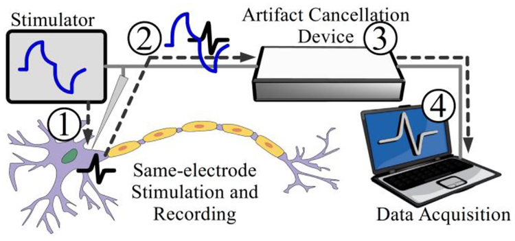
The conceptual system overview is illustrated in Fig. 1. A current stimulator injects pulses into the stimulation site of a neural tissue (intra- or extra-cellular), which generates a neural response and a large stimulus artifact on the same electrode. The resulting signal is processed by the artifact cancellation device where the artifact is suppressed in real-time to allow uninterrupted recording of neural responses. The device output is then streamed into a custom software application driven by a graphical user interface (GUI). The software algorithm completes the processing on-line and immediately presents the underlying neural signals to the user as a live plot.
Fig.1.
System overview: 1. A stimulus is injected into the cell and generates an artifact with a neural response. 2. The neural response is superimposed on the stimulus artifact waveform. 3. An artifact cancellation device suppresses the artifact and prevents amplifier saturation. 4. Software processing reveals the final neural signal without the stimulation artifact to the user.
A. Proposed Artifact Cancellation Methodology
The approach to cancel stimulus artifact presented here is based on the following four principles. First, the input voltage range of the recording circuitries must be sufficiently high to accommodate large stimulation artifacts, when recording near or at the stimulation site. This requires partial artifact removal at the input, before signal amplification, to avoid amplifier saturation and thus preserve continuous neural recording with high fidelity. Second, the system must have a sufficiently high SNR to record clean neural signals, which are multiple orders of magnitude smaller than the superimposed artifact. The noise must be carefully controlled, as artifact suppressing circuits prior to amplification will add noise directly to the recording. Third, the system must recover neural signals online. This accommodates closed-loop implants that need to continuously assess neural responses to adjust stimulation parameters in real-time. Finally, the method must allow programmable operation to enable design flexibility. The design methodology in this work satisfies the above principles by a solution that combines a hardware circuit topology and a software design, which together allows artifact-free neural recordings in real-time.
B. Proposed System Architecture
Fig. 2 shows the basic functional diagram of the proposed system divided into hardware and software modules. The hardware module consists of the analog amplifiers and filters, microcontroller unit (MCU) with custom firmware, analog-to-digital converter (ADC), and digital-to-analog converter (DAC) that together constitute the artifact cancellation device. The Data Acquisition Card (DAQ) relays the hardware output to the software module. The software module consists of the GUI and template-averaging algorithm. Both module designs take advantage of the fact that periodically incoming stimulus artifacts are relatively similar in shape and amplitude, since neural stimulation is commonly performed by a periodic train of pulses with fixed stimulus pulse amplitudes, widths, and inter-pulse delays. Any changes in the artifact waveform that happen due to naturally occurring electrode-tissue impedance drift during stimulation are accommodated in the hardware and software modules as well. The detailed functionality of each module is described below.
Fig. 2.
Block diagram of the hardware and software architectures.
The hardware module design reduces the artifact amplitude to meet the compliance requirement of the back-end amplifier without altering the neural signals. This is accomplished through an iterative hardware loop (Fig. 2). The loop consists of first storing the artifact as an initial template, then iteratively updating the template based on measured differences until the incoming artifact and stored template converge within the resolution of the hardware components. The final template is then subtracted from all following artifacts, and the result is amplified. The output of the hardware module at ith stimulation instance ohw (i), after convergence (i > c), can be described as:
| (1) |
where a(i) is any single artifact occurring after convergence, s(i) is the neural signal underlying the artifact, ã(c) is the digitized artifact template converged at iteration c, G is the output amplifier gain, and Δa(i) is the residual between the incoming artifact and stored template (Δa(i) = a(i) − ã(c)). The term s(i) × G in (1) is equivalent to amplifying a neural signal by a basic recording amplifier without the stimulus artifact, and is the component that is preserved and recovered in the later stages of the software signal processing. Each term in the equation represents a time segment spanning the duration of the artifact instance. The residual artifact, Δ(i), can be much larger than s(i) without information loss as long as the amplified sum ohw(i) is lower than the saturation voltage limits, Vhw_sat. Thus, hardware cancellation only requires that signal path accommodates:
| (2) |
assuming Δa(i) ≫ s(i), which is typically the case. For a fixed gain G, the maximum tolerated Δ(i) value defines the precision requirement for hardware components implementing acquisition and subtraction of the artifact (mainly ADC and DAC). The precision requirement above can be met with modest resolution data converters, reducing the complexity of the design implementation. An additional benefit is that a modest resolution data converter will not capture and subtract the neural signal alongside the artifact.
In contrast, a commercial front-end IC with a high-resolution ADC [25] could be used to accommodate a large stimulation artifact in simultaneous neural signal recording. However, a large section of the ADC’s highest weighted bits that represent the artifact will be discarded in post-processing, thereby reducing the available bits for the neural signal capture. For example, the front-end IC with 5.25 V supply and 24-bit ADC [25] would use 13 highest weighted bits to capture a 5 V artifact for subsequent removal in software domain, and only use the remaining 11 bits for digitizing a 0.5 mV neural signal. Such a design is inefficient and sub-optimal to implement in miniature SoC neural implants, where space and power are limited.
The software module in Fig. 2 eliminates residual artifacts from the hardware module output via generating and subtracting the software template. This template is generated by averaging multiple hardware output instances ohw(i). Each instance contains a residual stimulation-artifact waveform Δa(i) and an underlying neural signal segment s(i). The residual artifact is stable and periodic after hardware convergence (Δ(i) = Δa(j) for any i, j > c). The component (i) contains the incidental neural activity, which spans the duration of the artifact, and does not include the neural response, which occurs after the stimulation that caused it. The neural response after the artifact is freely passed to the output as the system prevents any amplifier saturation and signal loss. The incidental neural segment (i) underlying the artifact is uncorrelated to the stimulation and thus varies from one instance to another. Averaging this variance reduces (i) contribution below noise level (section IIID) but fully preserves the residual artifact component in the template [13]. The template is then subtracted from ohw(i) at each stimulation event to uncover the underlying neural signal. Thus both, the underlying incidental signals and stimulation responses, are revealed at system’s output. The output of the software module, osw(i), can be described as:
| (3) |
where the function averages k stimulation periods of ohw(j). The number (k) of segments to average is determined by signal analysis in section III D.
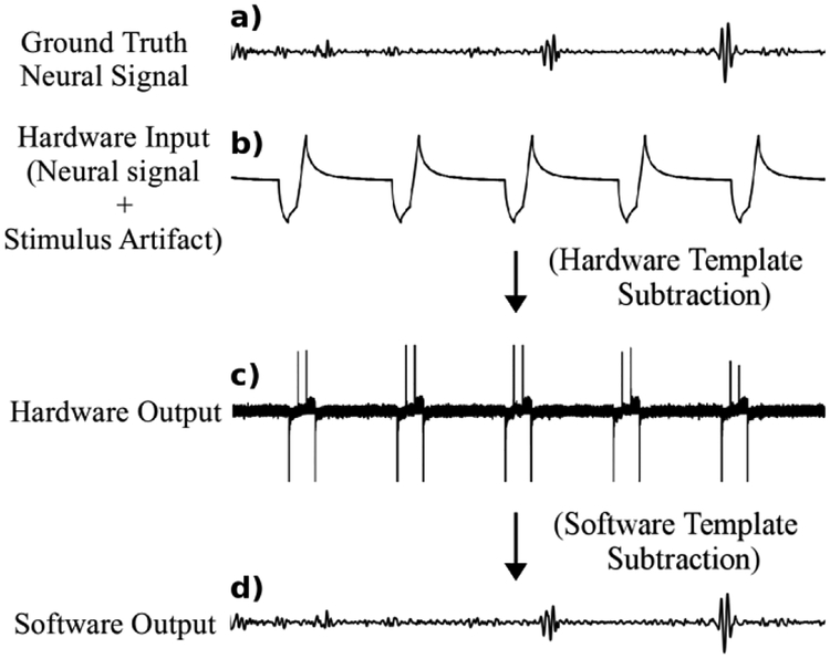
Fig. 3 illustrates the simulated input and output of the hardware and software modules during artifact cancellation. The signal a) is the ground truth neural signal. The signal b) is the system’s input – the sum of a periodic stimulus artifact and a pre-recorded ground-truth neural signal. The neural signal amplitude is several orders of magnitude smaller than the artifact, thus the latter dominates the summed waveform. The signal c) emulates the hardware module output – an amplified sum of the reduced residual artifacts and the neural responses, which meets the amplifier’s input range. Finally, the signal d) represents the software module output, which contains the neural signal without the artifact.
Fig. 3.
Simulations based on system equations illustrate signal transformation from contamination by a 1.2V artifact to recovered neural response with 100uV signal waveforms.
C. System Specifications
The specifications of the artifact cancellation system in Table I are derived to: 1) cancel stimulus artifacts orders of magnitude greater than the underlying neural signal, and 2) preserve the integrity of the neural signals during the recovery process. The input compliance voltage range is determined by the expected maximum artifact amplitude. This amplitude is estimated using the Randles cell model equation of an electrode [26], for typical stimulation settings provided below.
TABLE I.
| System Design Requirements Parameters | Values |
|---|---|
| Maximum stimulus artifact amplitude | 5 V |
| Minimum neural signal amplitude | 50 μV |
| Ratio of max. artifact to min. signal of interest | 100 dB |
| Maximum Gain | 60 dB |
| Bandwidth of signal interest | 1 Hz-10 kHz |
| Sampling Frequency | 100 kHz |
During rat cortex stimulation using a platinum ball electrode with 0.8 mm diameter and 50 μs pulses of 10 mA current [27] the artifact amplitude will be 4.99 V, as derived from [26] with Pt parameters from [28]. By the same token, intrafascicular sciatic nerve stimulation in cats using Utah electrode array with 0.005 mm2 exposed platinum tips [29] and 200 μs pulses of 50 μA [30] results in artifact amplitude of 0.198 V. Finally, [31] characterizes a typical DBS stimulation in-vivo with safe stimulation currents and pulse widths, and records resulting voltage amplitudes. The resulting maximum artifact amplitude is 3.4 V. To accommodate all listed applications by the proposed device, the input signal limit Vhw_sat is set to 5 V. This parameter also specifies the ADC and DAC full scale voltages.
On the other hand, extracellular action potential (AP) signal amplitude ranges 50–500 μV, while local field potentials (LFPs) have amplitudes 500 μV-5 mV [32]. The resulting ratio of the maximum artifact to minimum signal of interest is Vhw_sat/Vsig_min – is then 100,000 V/V, or 100 dB (20log scale). Additionally, to detect a 50 μV neural response with sufficient clarity, the noise must be 5–10x less. This is considered in design of software algorithm in section III–D.
Analog signal gain of the system, G, is programmable between 100 V/V and 1000 V/V, (40–60 dB), where a larger 5 mV LFP signal can be amplified back to 5 V at maximum gain. Combining the maximum gain and the set specifications with equation (2), a requirement for the residual artifact amplitude is defined as |Δa(t)| < 5 mV at the hardware module’s output. Recording bandwidth is set to frequency range from 1 Hz – 10 kHz for both AP and LFP signals [32].
III. DESIGN IMPLEMENTATION
The design topologies for analog components, data converters, MCU firmware and back-end software are chosen to satisfy system requirements defined in section IIC.
A. Analog Circuits
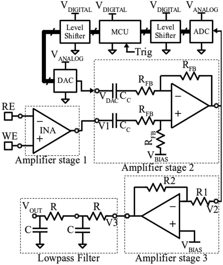
The analog signal chain shown in Fig. 4 consists of three amplifier stages connected in series. The first differentially records the input signal between the working and reference electrodes (WE and RE respectively), the second subtracts the hardware artifact template, and the third amplifies the signal for final processing by the software module.
Fig. 4.
Schematic of implementation of the hardware module for stimulation artifact cancellation.
The first stage is implemented using an Instrumentation Amplifier (INA111, Texas Instruments, TX, U.S.), which exhibits low noise, high precision subtraction, and insignificant input bias current. The minimal input bias current assures no disturbance to electrode-tissue interface at RE and WE electrodes. The amplifier gain is set to one, as amplification takes place only after artifact reduction is complete.
The second amplifier stage employs a capacitive input and resistive feedback and performs artifact subtraction at unity gain. Amplifier feedback is carefully designed to remain stable during fast edges and large-signal variations in common-mode and differential-mode signal components during template subtraction. Coupling capacitors Cc and feedback resistors Rfb are chosen to ensure the required low frequency cut-off point, noise level, and sufficient phase margin. The low frequency cutoff is set to comply with system specifications using the relationship fcLOW = 1/(2πRfbCcpl). Thermal noise generated by Rfb appears in the signal frequency band, and is considered in the design trade-off. The DAC signal is AC-coupled to negative input of the second stage to perform subtraction of the digitized template from the incoming artifact. The DAC is buffered with unity gain to ensure sufficient driving capability. The ADC is connected to the output of the second stage to acquire the hardware artifact template and update it until it converges with the incoming artifact within 1 LSB of the ADC.
The final output amplifier stage employs a programmable gain amplifier, where the feedback resistor can be programmed based on the need of the neural recording application. The output of this stage is loaded with a second order passive low- pass filter. The final amplifier stage is connected to the DAQ card, which digitizes the signal for the software algorithm.
B. Data Converters
The DAC outputs the digital template to cancel the incoming input artifact via the second stage (Fig. 4). To effectively filter out the DAC switching noise, the sampling frequency fs must be sufficiently higher than the neural signals recorded. Since the neural signals can contain components up to 10 kHz, fs is set at 100 kHz. A full decade of separation allows the passive filter to attenuate the switching waveforms without distorting the recording. The ADC fs must be the same as that of the DAC.
The hardware avoids capturing and subtracting the neural signals by choosing the correct ADC and DAC resolution. The resolution is set such that the LSB is larger than the expected neural signal amplitude prior to amplification. At 5 V full scale, 12-bit resolution sets LSB at 1.22 mV, near the maximum of an AP signal, while 10-bit sets LSB at 4.88 mV, near the maximum of an LFP signal. DAC and ADC components are chosen with 12-bit resolution. Adjustment to 10-bit resolution is performed by discarding the last 2 bits during MCU programming. This flexibility accommodates both neural signal types.
C. MCU Operations
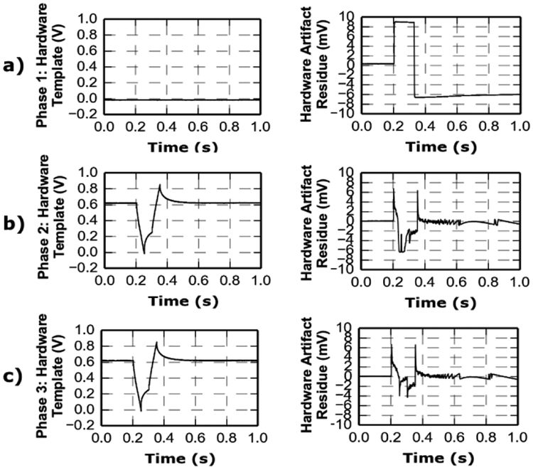
The MCU performs artifact cancellation in three distinct phases. Each phase is initiated by the stimulator trigger signal, which raises an internal interrupt for every stimulus event. During phase 1, the MCU employs the ADC to digitize and store the output of the raw artifact-contaminated neural signal at the second amplifier output. During phase 2, the MCU outputs the stored template via DAC to subtract the template from the incoming signal. The MCU simultaneously records the resulting residue at second amplifier output. The stored template is iteratively updated during phase 2 by accumulating the residue onto the stored template, which reduces the residue to prevent saturation of the following gain stage (Fig. 5). The number of required iterations depends on the asymmetry of the differential signal path in second stage (e.g. electrical component mismatch, conductor trace parasitics), but not on characteristics of the incoming signal. It is thus experimentally measured and then pre-programmed at initial testing. During phase 3, the DAC outputs the final converged template to cancel all following artifacts. The output of this phase is the amplified sum of the neural signal and minimized residual artifacts as described in (1). If stimulation protocol is deliberately changed, causing large changes to artifact waveform, the MCU is then reset back to phase 1 to recalibrate to the new artifact. Lastly, an experiment protocol with multiple stimulation patterns can be accommodated by recording and pushing the corresponding templates into MCU memory stack at initial test and sequencing them by an external control pin as needed during experiment.
Fig. 5.
Illustration of MCU’s operational phases in hardware artifact subtraction. Left column: artifact template stored in MCU memory. Right column: residual artifact after hardware reduction. a) Phase 1: output saturates before initial template is acquired. b) Phase 2: the acquired template is subtracted but leaves areas of saturation in the residual artifact. c) Phase 3: the updated artifact template is subtracted and results in a smaller artifact residue, displaying no saturation as desired.
D. Software
Prior to software signal processing, the DAQ card NI 6259 M Series, (National Instruments, Austin, TX, U.S.) digitizes the hardware device output. The device output, along with the trigger signals indicating the start of each stimulus, are simultaneously read via the DAQ card into the GUI software. The software performs signal processing online and displays results live. The algorithm and GUI are implemented in Python (Python Software Foundation, https://www.python.org/).
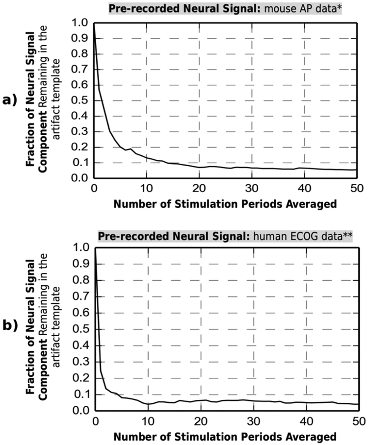
The core of the software design is the template averaging algorithm that aligns the trigger signal with the hardware device output and extracts segments of stimulation artifact, each containing a residual artifact Δa(i) and an underlying neural activity segment s(i) (3). As mentioned in section IIB, the neural response, which occurs any time after the stimulation that caused it, is not included in s(i) and thus passes unaltered to the output. The s(i) instead contains an incidental neural signal that spans the artifact, is uncorrelated to stimulation and thus varies from instance to instance. The algorithm preserves the consistent Δa(i) and suppresses the varying s(i) by averaging the last k instances. The number k is chosen to reduce the averaged s(i) component to a size below the system’s noise requirement (section IIC), which is 0.1 of the amplitude of the original neural signal s(i).
Two pre-recorded neural signals (AP and LFP) are analyzed in Fig. 1 to determine the optimal k. The plots show the tradeoff between k and the fraction of the neural signal remaining in the generated template. k = 20 meets the requirement with a safe margin in both cases. In a case with a different signal type, this number can also be set experimentally during initial recording to reduce the artifact residue by a template generated with sufficient averaging. The averaged artifact template is then subtracted from each individual residual artifact at the hardware device output, and the final result is displayed to the user. The running-average live algorithm dynamically adapts to any changes in the artifact waveform caused by chemical drift at the electrode-tissue interface. These drifts are small, don’t pose risk of saturation and don’t affect the hardware module operation.
Fig.6.
Trade-off exists between number of stimulation periods averaged and fraction of neural signal component in the generated artifact template. The trade-off is analyzed for: a) Mouse AP data*, b) Human ECOG data**.
IV. IN-VITRO EXPERIMENTAL RESULTS
A. In-Vitro Test Setup
The prototype device is initially tested in-vitro with stainless steel wire electrodes (AS632, Cooner Wire, U.S.) immersed in saline (0.90% NaCl). The electrode impedance is measured to be ~5 kΩ at 1 kHz. The setup is configured for same-electrode stimulation and recording, as in Fig. 1. The working electrode is connected to both, the current stimulator developed in our prior work [33] and the positive input of the recording device. The reference electrode connects to the negative terminal of the recording device. The ground electrode is connected to the ground terminal of the device and the stimulator. An additional wire electrode injects pre-recorded neural signals into the saline.
B. In-Vitro Test Results
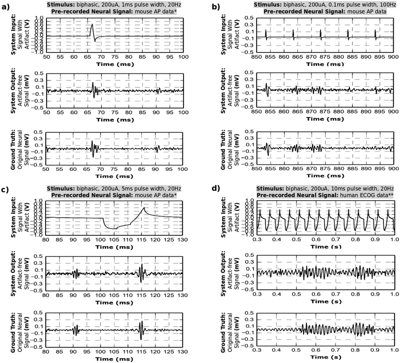
The versatility and capability of the prototype device is demonstrated in four distinct test cases, with different test conditions, as labeled in Fig. 7. In each test, the working electrode directly records the artifact from the stimulator, while simultaneously picking up the injected pre-recorded neural signal from saline. The neural signal overlaps in time domain with stimulation artifact. The artifact is suppressed in real-time to prevent saturation and the fully recovered neural signal captured for visual analysis in Fig. 7 (a)-(d). The system input plot shows the pre-recorded neural signal with the superimposed artifact; the artifact is much larger than the neural signal and thus dominates the waveform. The system output plot displays the recovered neural signal after full hardware an software artifact cancellation, normalized by the gain. The ground truth plot shows the original signal injected into saline.
Fig. 7.
The system is tested in-vitro in a saline solution with the same-electrode stimulation and recording setup. The electrode impedance is ~5 kΩ at 1kHz. Four different stimulation protocols are used, while a pre-recorded neural signal is injected into the saline. For each case, the system input contains a neural signal and a stimulation artifact. The artifact is canceled with hardware and software real-time processing and the neural signal is recovered. The recovered signal closely resembles the ground truth.
* (a)-(c) uses Mouse Action Potentials pre-recorded from hippocampus [28].
** (d) uses human ECoG data containing fast-gamma waves. Data is provided to us courtesy of Dr. Yue-Loong Hsin, Biomedical Electronics Translation Research Center at the National Chiao Tung University, Taiwan.
Each of the test cases demonstrate full signal recovery throughout the entire length of the stimulation artifact. In test (c), the neural spike of interest underlies the anodic phase of the artifact. In the other three cases, the neural spikes (or fast gamma waves) span the full length of the artifact(s). The neural signal is recovered in all four cases. An added noise is observed in the recovered signals and shows no dependency on stimulation conditions. Test (d) shows the most pronounced distortion of recovered neural signals. The fast gamma signal is distorted due to residual artifact by less than 100 μV relative to ground truth, which translates to a reduction of the raw 1.2 V artifact by more than 100 dB (20 dB scale). Test data is further analyzed in time and frequency domains in the next subsection.
C. Signal Correlation
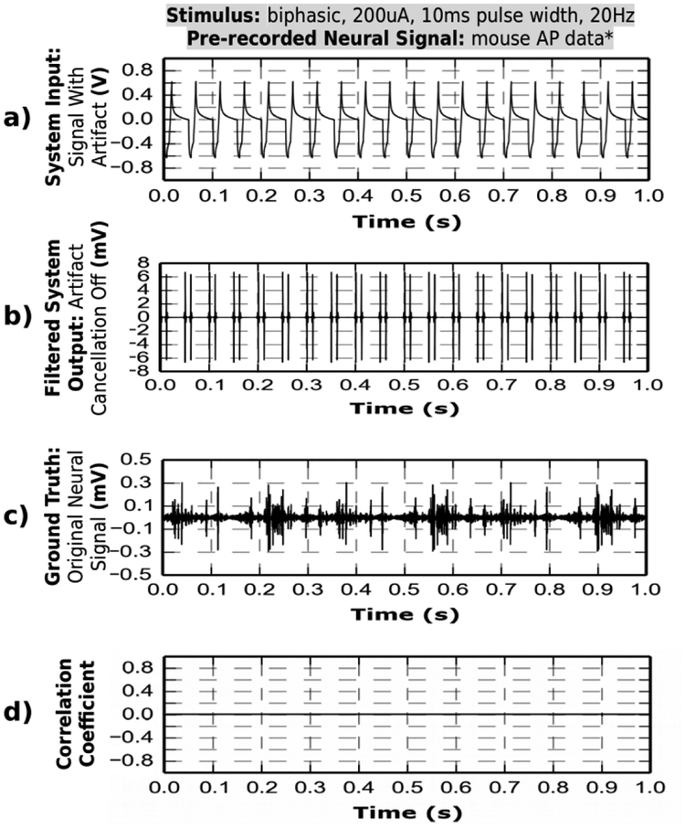
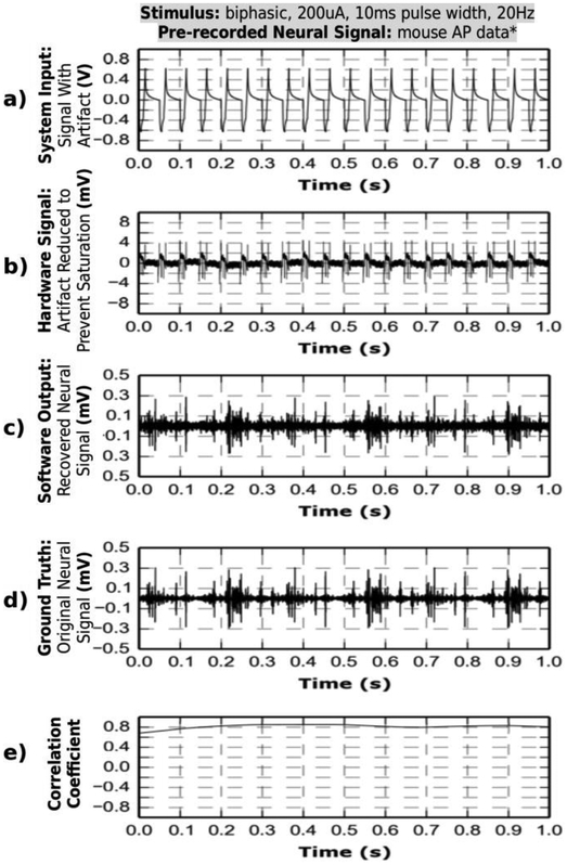
The Pearson correlation coefficient between the recovered neural signal and the ground truth is displayed before and after artifact cancellation is applied in Fig. 8 and Fig. 9, respectively. As discussed earlier, when artifact cancellation is not performed, the amplifier saturates at the hardware module and cannot record the signal of interest. Fig. 8a shows the device input (sum of stimulation artifacts and a pre-recorded neural signal) to the system with artifact cancellation turned off. Fig. 8b shows the resulting system output. The output signal is filtered with a 350–5000 Hz band-pass filter by the software in an attempt to recover the neural signal APs. The neural signal ground truth is shown in Fig. 8c. Fig. 8d shows zero correlation between filtered system output and the ground truth, which confirms signal loss due to amplifier saturation. In contrast, saturation is avoided when artifact cancellation is enabled (Fig. 9) and signal is successfully recovered with an average Pearson correlation coefficient of 0.83. The non-ideal recovery is attributed to signal distortion by the system noise.
Fig. 8.
Artifact cancellation feature is disabled and simple frequency filtering is applied to amplifier’s output by the software. Amplifier is saturated and incurs complete signal loss. Pearson correlation coefficients between output signal and the ground truth are zero, confirming that output waveforms do not contain any valid neural signals.
Fig. 9.
Artifact cancellation by hardware device prevents any amplifier saturation. The hardware output contains the neural signal component, which is recovered via software algorithm. Pearson correlation coefficients between output signal and the ground truth is of ~0.8, which demonstrates that the recovered neural signal contains valid data.
D. Frequency Spectrum Analysis
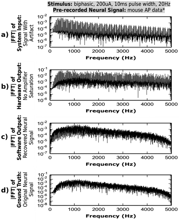
Fig. 10 shows the Fourier transform plots of the signals at various stages of the artifact cancellation system. Since the stimulus artifact waveform is periodic and has high edge rates, it has a frequency content similar to that of a square wave. This content is a set of large periodic harmonics throughout the full spectrum of hardware module input (a) and output (b). In contrast, plot (c) illustrates the recovery of the neural signal free of such artifact harmonics. In addition, the similarity between the Fourier transforms of the recovered signal (c) and the ground truth (d), indicates that the neural signal is preserved with minimal distortion, as previously seen in the time domain.
Fig. 10.
Frequency spectrum of system input signal contains artifact harmonics. The harmonics are minimized and amplified at hardware output. Software algorithm, removes the residual artifact producing output with spectrum similar to that of the ground truth.
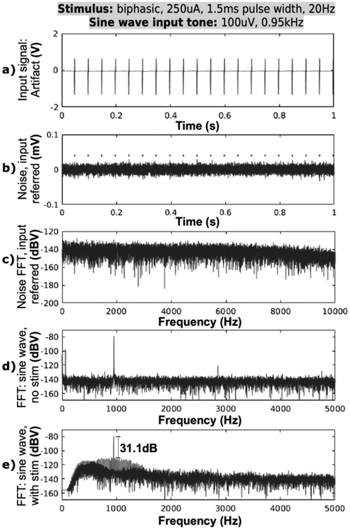
In addition, the system was tested in-vitro with a 2 V stimulation artifact at 20 Hz injected at the input without any neural signal, and the output spectrum was used to calculate the effective system noise post-cancellation (Fig. 11a–c). The integrated input-referred noise was calculated to be 9.7 μVrms and 9.4 μVrms for 1 Hz-10 kHz band and 300 Hz-10 kHz band, respectively. The total noise is contributed by amplifiers and the DAC and the output amplifier’s noise is normalized by its gain.
Fig. 11.
The prototype system is tested in-vitro for noise and distortion. a)-c) A 2V stimulation artifact is cancelled by the system. Output noise includes residual artifacts and integrates to 9.7μVrms in 1 Hz-10 kHz band. d) The system exhibits THD=0.88% for a 100 μV sine wave without stimulation. e) When 2V stimulation artifact is applied and cancelled, the system incurs distortion 31.1dB below the 100μV sine wave tone. The distortion spurs are spaced 20Hz apart and are products of mixing between the large artifact and the small sine wave signals in the amplifier chain.
Furthermore, a 100 μV sine wave was injected with and without 20Hz stimulation to measure system’s signal distortion (Fig. 11d,e). The chain of amplifiers in the system exhibits THD of 0.88% for 100 μV sine wave input. It produces distortion spurs at −111dBV, which is 31dB below the −80dBV sine wave tone after artifact cancellation. The distortion spurs are spaced 20Hz apart from the fundamental tone, and occur due to mixing between the repeating artifact and the injected sine wave.
V. IN-VIVO EXPERIMENTAL RESULTS
A. Animal Preparation and Electrode Implantation
The prototype device is further tested in a male Sprague Dawley rat (255 grams) in-vivo. The animal was anesthetized with isofluorane (2%) to a depth of anesthesia that does not elicit response to foot pinch or reflexive paw response to ear bars. A midline scalp incision was made to expose the midsagittal suture from bregma to lambda, the skin retracted and galea was cleaned from the skull to allow dental acrylic to adhere at the end of the procedure. Using a variable-speed Dremel drill with sterilized jewelers screw-sized bit, very small holes were drilled bilaterally to allow the passage of recording microwires to underlying cortical and subcortical tissue. A pair of tungsten microwires (50 μm OD) with 1.0mm distance between the tips was implanted bilaterally into the left (LSu) and right (RSu) hippocampal subiculum area (coordinates: AP=−6.7; ML=4.6; DV=4.0) based on [34]. The impedance of the microwire electrodes was measured to be~100 kΩ at 1kHz. Only one electrode was simultaneously stimulated and recorded at a time for in-vivo testing of the device prototype. The reference and ground screw electrodes were placed in the cerebellum near the mid line at a distance 1mm from each other. Surgery and all experimental procedures were approved by the Chancellor’s Animal Research Committee of David Geffen School of Medicine at UCLA. Experiments were carried out under freely moving conditions to record brain activity for verification of successful electrode implantation.
B. In-vivo Test Setup
Stimulator and artifact cancellation system prototype share the same working electrode and are connected similarly to the in vitro setup. A commercial neural recording amplifier (RHD 2132, Intan Technologies, CA, U.S.) is connected in parallel with the prototype for a side-by-side comparison of the recordings during stimulation onset. An electrode in the hippocampus area is chosen for stimulation and recording due to relatively high excitability and expected abundance of neural responses. Similar set-up for the in vitro experiment is reused here. Stimulation parameter limits are chosen experimentally to avoid disturbance to the animal. The pulse amplitude and duration parameters are swept at stimulation frequency of 1 Hz, while monitoring the recorded output. The selected frequency avoids neuron fatigue, while the selected amplitude of 33 μA and the duration of 0.3 ms generate adequate neural responses, without altering the animal’s behavior. When this stimulus current is injected into the impedance of the implanted electrode it generates an artifact with and amplitude of ~0.8 V. (Fig. 12a).
Fig. 12.
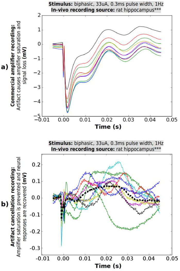
In-vivo same-electrode stimulation and recording test is made using commercial neural amplifier (RHD 2132, Intan Technologies, CA, U.S.). a) Stimulation artifact presented at the input of the amplifier has an amplitude of ~0.8 V. b) Commercial amplifier saturates at each stimulation event due to a large artifact and its output shows ~180s of milliseconds of saturation recovery, incurring complete signal loss before returning to normal recording.
*** Animal recording was made available to us courtesy of Dr. Anatol Bragin, Department of Neurology at University of California, Los Angeles, CA, U.S.
C. In-vivo Test Results
The recording output from the commercial amplifier by Intan Technologies is displayed in Fig. 12b. The amplifier saturates, as the amplitude of the stimulation artifact exceeds amplifier’s input range (−4 mV to +4 mV) at gain of 1000 V/V by two orders of magnitude. The saturation and recovery periods last hundreds of milliseconds until the system’s amplifier settles back to normal operation. During this period the neural responses are lost without any possibility of recovery by post processing. Fig. 13a shows extracted consecutive segments of the recorded data in response to ten consecutive stimulation events. The segments are overlaid as a family of curves, and the stimulation event for each occurs at zero seconds. Each individual curve displays consistent saturation behavior bearing no information of neural signals present during this time period.
Fig. 13.
In-vivo same-electrode simultaneous stimulation and recording. 10 consecutive segments triggered by the stimulation event are extracted from the recording and overlapped. a) Commercial neural amplifier recording shows amplifier’s saturation and slow recovery, which completely conceals neural responses. b) Proposed design suppresses a large artifact, prevents saturation and recovers neural responses. 10 responses are overlaid and the average is plotted with dashed line. The output waveform contains a remaining fraction of the artifact waveform, which is discussed in sub-section V-C below.
The designed prototype connects in parallel to the same electrodes, cancels the artifact and avoids the unrecoverable signal loss. The resulting recording was dissected into stimulation-triggered segments. Fig. 13 b shows 10 consecutive segments extracted from a single recording instance and overlaid as a family of curves. The average of 10 curves is plotted with a dashed line. The curves display the neural responses to each stimulation instance. In contrast to commercial amplifier data in (a), this device avoids saturation and preserves the neural response waveforms. Response magnitudes range 100–200 μV, with pulse durations 10–20 ms. The characteristics of the recorded neural responses match previously reported studies of local neural network responses to stimulation (e.g. [35]).
The waveforms recorded in-vivo still contain a residual fraction of the stimulation artifact. This residual component, not cancelled by the template subtraction algorithms, is a result of the stimulator’s random output noise. The noise is much more pronounced in the in-vivo recordings compared to in-vitro due to scarring formed around the in-vivo electrodes. The electrodes used for recording were implanted in this animal for several months, incurring inflammation and scarring [36]. The scar tissue formed around the electrode prevented neuron AP recording (larger group responses were captured instead) and increased the electrode impedance from baseline 100 kΩ to an impedance several times higher. The higher impedance results in higher voltage noise for a given stimulator current noise. Notably, the system still achieves artifact suppression from ~0.8 V amplitude to a noisy residue less than ~300 μV (more than three orders of magnitude reduction) and recovers the neural signals in-vivo in same-electrode stimulation and recording. In a case with an electrode specifically designed for long-term recording, the scarring and thus impedance are expected to be better controlled, allowing better artifact cancellation.
In comparison to the amplifier blanking approach, which avoids recording during stimulation, this design prevents saturation of the amplifier and allows uninterrupted recording. In cases with better controlled stimulator noise and/or electrode impedance (as with in-vitro results), a full artifact removal can be achieved. Whereas the blanking approach makes it impossible regardless of the stimulator and electrode characteristics.
Generally, the issue of stimulator noise is not considered in previously published artifact-cancellation works that record at a distance from the stimulation site, where artifact effects are greatly attenuated. Relatively, the challenging same-electrode setup will confront a much larger artifact and consequently a larger stimulator noise. This noise will be higher in current-mode stimulation with high-impedance electrodes (e.g. penetrating Multi-Electrode Arrays) or with noisy voltage-mode stimulators. Both scenarios motivate the designs of custom low-noise stimulators to achieve better cancellation.
VI. DISCUSSION
A. Use of Adaptive Filters in the Software Module
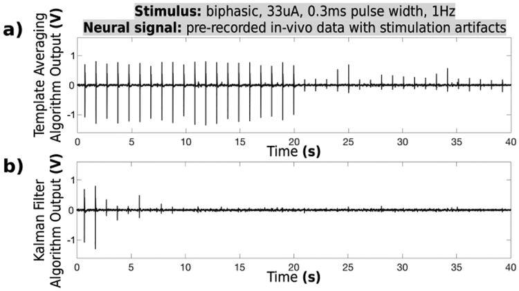
The real-time software algorithm is designed to use 20 initial artifact samples to compute a usable template waveform and cancel the input signal artifacts in real-time (section IIID). The approach is suitable for mapping neural networks in-vitro and in-vivo by simultaneous stimulation and recording, and in many closed-loop neural prosthetics which use high frequency trains for neural modulation. The approach may not be desired in some closed-loop applications, which use low stimulus count for each neural modulation event. To reduce the number of initial artifacts needed for creating a template, an adaptive Kalman filter algorithm was tested and compared to the original artifact averaging. Both approaches were applied in post-processing to a raw in-vivo recording taken at the output of the hardware module. Fig. 14 shows the resulting waveforms for each filter. The Kalman filter requires significantly fewer artifacts to perform effective cancellation, due to its inherently faster convergence.
Fig. 14.
Template averaging is compared to Kalman filter approach for software artifact cancellation. a) Averaging algorithm used in this design requires 20 initial artifact samples to generate an accurate template. b) Kalman filter algorithm requires only four initial samples to converge.
B. Application to Multi-Channel Neural Interfaces
In multi-channel devices with simultaneous recording and stimulation the proposed artifact cancellation hardware circuits would be inserted between inputs of the affected recording channels and the gain amplifier (corresponding to WE input and Stage 3 gain amplifier in Fig. 4 respectively), acting to prevent saturation as previously described. To minimize the circuit overhead, groups of channels with similar artifact magnitude can share the same hardware template, effectively sharing a single ADC input/DAC output. With respect to the hardware template precision (1LSB), the artifact magnitude is similar at all electrodes equidistant to the site of stimulation. Thus a planar electrode array with n2 channels or 3D array with n3 channels will only require between n/2 and n hardware template ADC/DAC channels. Additional ADC/DAC channels can be added if an electrode array spans multiple tissue structures, where artifact waveform changes across the barrier between them. On the contrary, any distant electrode channels recording a small artifact don’t risk saturation, don’t require the cancellation circuitry and can be recorded with standard amplifiers directly. Multi-channel implementation can use a low-power FPGA or custom ASIC as a controller to efficiently accommodate parallel tasks of storing and generating templates for multiple channels at once. But an MCU can still be used by communicating the templates sequentially to a multi-channel DAC with a simultaneous output option. Finally, the software module would be embedded into the recording application to complete the artifact cancellation for all recorded channels.
C. Implementation in neural interface SoC
The proposed methodology is also envisioned in a SoC neural interface as a modular design. The design will require only a limited number of artifact template (ADC/DAC) channels to accommodate a large number of recording input slices (see section VIB). Each recording slice will contain a basic gain amplifier, preceded by a template subtraction amplifier (stage 2 amplifier in Fig. 4). Subtraction terminals of slices with similar artifact magnitudes will be assigned to one artifact template channel. The assignment would be facilitated by a multiplexing circuitry programmed post electrode’s implantation during initial testing and calibration.
The subtracting amplifiers in recording slices will meet the required low-noise performance by standard design methods. The overhead area and power for the hardware module’s digital controller would be minimal in sub-micron CMOS technologies.
D. Comparison to Previous Works
Recent and past works demonstrating results with artifact cancellation by use of analog and digital design approaches are summarized in Table II. To the best of these authors’ knowledge, the proposed work is the first to achieve neural response recovery in-vivo while simultaneously stimulating and recording in the same electrode during large artifact events.
TABLE II:
Comparison with Other Published Works
| [3] | [7] | [8] | [11] | [15] | [20] | This work | |
|---|---|---|---|---|---|---|---|
| Domain of the solution | Analog | Analog | Analog/Digital | Analog | Digital | Digital | Analog/Digital/SW |
| Same-electrode stim/record? | No | Yes | No | No | No | No | Yes |
| Unconstrained electrode setup? | No | No | Yes | Yes | N/A | Yes | Yes |
| Prevents saturation? | Yes | No | No | Yes | No | N/A | Yes |
| Maximum tolerated artifact | 10V | N/S | 10mV | N/S | N/S | 100mV/40mV** | 5V |
| Signal bandwidth | 10V | 361Hz-10kHz | 1Hz-2kHz | 100Hz-5kHz | N/S | 1Hz-5kHz | 1–10kHz |
| In-band noise | ~1uVrms | N/S | 5uVrms | 4.2uVrms | N/S | N/A | 9.7uVrms |
| Artifact suppression ratio | 24dB | N/S | 42dB | N/S | 20dB* | 49dB | 100dB |
not specified; estimated from test data
specified for LFP and neural spikes respectively
VII. CONCLUSION
The implementation of the proposed methodology demonstrates simultaneous neural stimulation and recording on the same electrode, uniquely recovering the neural signal with minimal distortion under the presence of a superimposed stimulation artifact with magnitude approximately 100dB higher than the signal of interest. The design distributes the artifact cancellation task into a two-part solution with a novel hardware architecture at the front-end of the system, and concurrent real-time software algorithm at the back-end. The prototype is implemented using off-the-shelf components, a custom PCB, and a custom GUI-driven live software algorithm.
In-vitro test results demonstrate full neural signal recovery before, during, and after stimulus artifact events. In-vivo experimental results with a rodent model show neural responses recovered in the presence of large stimulation artifacts, in contrast to a commercial neural amplifier system used in parallel, which incurred saturation and unrecoverable signal loss under the same conditions. This design can be used to map neural networks in tissues by recording the propagation of neural responses starting at the stimulation site. Critically, this design does not constrain its use to: 1) deliberately setting the stimulation frequency to be out of band with signals of interest, 2) placing the recording electrodes symmetrically around the stimulation electrode to treat the artifact as a common-mode noise. The authors envision the proposed architecture to be suitable for future designs of closed-loop neural interfaces. To that end the authors are in the process of developing and integrating this design onto a SoC.
VIII. ACKNOWLEDGEMENT
The authors would like to thank Dr. Anatol Bragin for providing the opportunity and supporting in-vivo testing of the design prototype. The authors would also like to acknowledge and thank Dr. Yue-Loong Hsin for providing human ECoG recording for our in-vitro design prototype validation.
This work is partially funded by the Endowment for the Chan Soon-Shiong Bionic Engineering Research Center at UCLA by California Capital Equity LLC and NIH BRP U01 EB007615.
REFERENCES
- [1].Rolston JD, Gross RE, and Potter SM, “A low-cost multielectrode system for data acquisition enabling real-time closed-loop processing with rapid recovery from stimulation artifacts,” Front. Neuroengineering, vol. 2, p. 12, 2009. [DOI] [PMC free article] [PubMed] [Google Scholar]
- [2].Hottowy P et al. , “Properties and application of a multichannel integrated circuit for low-artifact, patterned electrical stimulation of neural tissue,” J. Neural Eng, vol. 9, no. 6, p. 066005, Dec. 2012. [DOI] [PMC free article] [PubMed] [Google Scholar]
- [3].Stanslaski S et al. , “Design and validation of a fully implantable, chronic, closed-loop neuromodulation device with concurrent sensing and stimulation,” IEEE Trans. Neural Syst. Rehabil. Eng. Publ. IEEE Eng. Med. Biol. Soc, vol. 20, no. 4, pp. 410–421, Jul. 2012. [DOI] [PubMed] [Google Scholar]
- [4].Wichmann T and Devergnas A, “A novel device to suppress electrical stimulus artifacts in electrophysiological experiments,” J. Neurosci. Methods, vol. 201, no. 1, pp. 1–8, Sep. 2011. [DOI] [PMC free article] [PubMed] [Google Scholar]
- [5].Brown EA, Ross JD, Blum RA, Nam Y, Wheeler BC, and DeWeerth SP, “Stimulus-Artifact Elimination in a Multi-Electrode System,” IEEE Trans. Biomed. Circuits Syst, vol. 2, no. 1, pp. 10–21, Mar. 2008. [DOI] [PubMed] [Google Scholar]
- [6].Gnadt JW, Echols SD, Yildirim A, Zhang H, and Paul K, “Spectral cancellation of microstimulation artifact for simultaneous neural recording in situ,” IEEE Trans. Biomed. Eng, vol. 50, no. 10, pp. 1129–1135, Oct. 2003. [DOI] [PubMed] [Google Scholar]
- [7].Nag S, Sikdar SK, Thakor NV, Rao VR, and Sharma D, “Sensing of Stimulus Artifact Suppressed Signals From Electrode Interfaces,” IEEE Sens. J, vol. 15, no. 7, pp. 3734–3742, Jul. 2015. [Google Scholar]
- [8].Mendrela AE et al. , “A Bidirectional Neural Interface Circuit With Active Stimulation Artifact Cancellation and Cross-Channel Common-Mode Noise Suppression,” IEEE J. Solid-State Circuits, vol. 51, no. 4, pp. 955–965, Apr. 2016. [Google Scholar]
- [9].Xu J, Wu T, Liu W, and Yang Z, “A Frequency Shaping Neural Recorder With 3 pF Input Capacitance and 11 Plus 4.5 Bits Dynamic Range,” IEEE Trans. Biomed. Circuits Syst, vol. 8, no. 4, pp. 510–527, Aug. 2014. [DOI] [PubMed] [Google Scholar]
- [10].“Front Ends - Ripple Neuro.” [Online]. Available: http://rippleneuro.com/front-ends. [Accessed: 30-Apr-2017].
- [11].Yang Z, Xu J, Nguyen AT, Wu T, Zhao W, and k Tam W, “Neuronix enables continuous, simultaneous neural recording and electrical microstimulation,” in 2016 38th Annual International Conference of the IEEE Engineering in Medicine and Biology Society (EMBC), 2016, pp. 4451–4454. [DOI] [PubMed] [Google Scholar]
- [12].Heffer LF and Fallon JB, “A novel stimulus artifact removal technique for high-rate electrical stimulation,” J. Neurosci. Methods, vol. 170, no. 2, pp. 277–284, May 2008. [DOI] [PMC free article] [PubMed] [Google Scholar]
- [13].Hashimoto T, Elder CM, and Vitek JL, “A template subtraction method for stimulus artifact removal in high-frequency deep brain stimulation,” J. Neurosci. Methods, vol. 113, no. 2, pp. 181–186, Jan. 2002. [DOI] [PubMed] [Google Scholar]
- [14].Al-ani T, Cazettes F, Palfi S, and Lefaucheur J-P, “Automatic removal of high-amplitude stimulus artefact from neuronal signal recorded in the subthalamic nucleus,” J. Neurosci. Methods, vol. 198, no. 1, pp. 135–146, May 2011. [DOI] [PubMed] [Google Scholar]
- [15].Limnuson K, Lu null Hui, Chiel HJ, and Mohseni P, “Real-Time Stimulus Artifact Rejection Via Template Subtraction,” IEEE Trans. Biomed. Circuits Syst, vol. 8, no. 3, pp. 391–400, Jun. 2014. [DOI] [PubMed] [Google Scholar]
- [16].Allen DP, Stegemöller EL, Zadikoff C, Rosenow JM, and MacKinnon CD, “Suppression of deep brain stimulation artifacts from the electroencephalogram by frequency-domain Hampel filtering,” Clin. Neurophysiol, vol. 121, no. 8, pp. 1227–1232, Aug. 2010. [DOI] [PMC free article] [PubMed] [Google Scholar]
- [17].Wichmann T, “A digital averaging method for removal of stimulus artifacts in neurophysiologic experiments,” J. Neurosci. Methods, vol. 98, no. 1, pp. 57–62, May 2000. [DOI] [PubMed] [Google Scholar]
- [18].Sekirnjak C, Hottowy P, Sher A, Dabrowski W, Litke AM, and Chichilnisky EJ, “High-Resolution Electrical Stimulation of Primate Retina for Epiretinal Implant Design,” J. Neurosci, vol. 28, no. 17, pp. 4446–4456, Apr. 2008. [DOI] [PMC free article] [PubMed] [Google Scholar]
- [19].Chandrakumar H and Marković D, “A High Dynamic Range Neural Recording Chopper Amplifier for Simultaneous Neural Recording and Stimulation,” J. Solid-State Circuits, vol. 52, no. 3, pp. 645–2017. [Google Scholar]
- [20].Basir-Kazeruni S, Vlaski S, Salami H, Sayed AH, and Marković D, “A blind Adaptive Stimulation Artifact Rejection (ASAR) engine for closed-loop implantable neuromodulation systems,” in 2017 8th International IEEE/EMBS Conference on Neural Engineering (NER), 2017, pp. 186–189. [Google Scholar]
- [21].Johnson BC et al. , “An implantable 700 uW 64-channel neuromodulation IC for simultaneous recording and stimulation with rapid artifact recovery,” in 2017 Symposium on VLSI Circuits, 2017, pp. C48–C49. [Google Scholar]
- [22].Zhou A et al. , “WAND: A 128-channel, closed-loop, wireless artifact-free neuromodulation device,” ArXiv170800556 Q-Bio, Aug. 2017. [Google Scholar]
- [23].Yochum M and Binczak S, “A wavelet based method for electrical stimulation artifacts removal in electromyogram,” Biomed. Signal Process. Control 22, pp. 1–10, Sep. 2015. [Google Scholar]
- [24].Culaclii S, Kim B, Lo YK, and Liu W, “A hybrid hardware and software approach for cancelling stimulus artifacts during same-electrode neural stimulation and recording,” in 2016 38th Annual International Conference of the IEEE Engineering in Medicine and Biology Society (EMBC), 2016, pp. 6190–6193. [DOI] [PubMed] [Google Scholar]
- [25].“TI ADS1299 Medical Analog Front End.” [Online]. Available: http://www.ti.com/product/ads1299. [Accessed: 19-Oct-2016].
- [26].Lo Y-K, Chang C-W, and Liu W, “Bio-impedance characterization technique with implantable neural stimulator using biphasic current stimulus,” Conf. Proc. Annu. Int. Conf. IEEE Eng. Med. Biol. Soc. IEEE Eng. Med. Biol. Soc. Annu. Conf, vol. 2014, pp. 474–477, 2014. [DOI] [PMC free article] [PubMed] [Google Scholar]
- [27].Koyanagi I and Tator CH, “The effects of cortical stimulation, anesthesia and recording site on somatosensory evoked potentials in the rat,” Electroencephalogr. Clin. Neurophysiol, vol. 101, no. 6, pp. 534–542, Dec. 1996. [DOI] [PubMed] [Google Scholar]
- [28].Franks W, Schenker I, Schmutz P, and Hierlemann A, “Impedance characterization and modeling of electrodes for biomedical applications,” IEEE Trans. Biomed. Eng, vol. 52, no. 7, pp. 1295–1302, Jul. 2005. [DOI] [PubMed] [Google Scholar]
- [29].Branner A, Stein RB, and Normann RA, “Selective stimulation of cat sciatic nerve using an array of varying-length microelectrodes,” J. Neurophysiol, vol. 85, no. 4, pp. 1585–1594, Apr. 2001. [DOI] [PubMed] [Google Scholar]
- [30].McDonnall D, Clark GA, and Normann RA, “Interleaved, multisite electrical stimulation of cat sciatic nerve produces fatigue-resistant, ripple-free motor responses,” IEEE Trans. Neural Syst. Rehabil. Eng. Publ. IEEE Eng. Med. Biol. Soc, vol. 12, no. 2, pp. 208–215, Jun. 2004. [DOI] [PubMed] [Google Scholar]
- [31].Wei XF and Grill WM, “Impedance characteristics of deep brain stimulation electrodes in vitro and in vivo,” J. Neural Eng, vol. 6, no. 4, p. 046008, Aug. 2009. [DOI] [PMC free article] [PubMed] [Google Scholar]
- [32].Gosselin B, “Recent Advances in Neural Recording Microsystems,” Sensors, vol. 11, no. 5, pp. 4572–4597, Apr. 2011. [DOI] [PMC free article] [PubMed] [Google Scholar]
- [33].Lo YK, Chen K, Gad P, and Liu W, “A Fully-Integrated High-Compliance Voltage SoC for Epi-Retinal and Neural Prostheses,” IEEE Trans. Biomed. Circuits Syst, vol. 7, no. 6, pp. 761–772, Dec. 2013. [DOI] [PubMed] [Google Scholar]
- [34].Paxinos G and Watson C, The Rat Brain in Stereotaxic Coordinates, 6th ed. New York: Academic, 2006. [Google Scholar]
- [35].Butovas S, Hormuzdi SG, Monyer H, and Schwarz C, “Effects of electrically coupled inhibitory networks on local neuronal responses to intracortical microstimulation,” J. Neurophysiol, vol. 96, no. 3, pp. 1227–1236, Sep. 2006. [DOI] [PubMed] [Google Scholar]
- [36].Polikov VS, Tresco PA, and Reichert WM, “Response of brain tissue to chronically implanted neural electrodes,” J. Neurosci. Methods, vol. 148, no. 1, pp. 1–18, Oct. 2005. [DOI] [PubMed] [Google Scholar]


