

Abstract
Recently, the fabrication methods of orthopedic implants and devices have been greatly developed. Additive manufacturing technology allows the production of complex structures with bio-mimicry features, and has the potential to overcome the limitations of conventional fabrication methods. This review explores open-cellular structural design for porous metal implant applications, in relation to the mechanical properties, biocompatibility, and biodegradability. Several types of additive manufacturing techniques including selective laser sintering, selective laser melting, and electron beam melting, are discussed for different applications. Additive manufacturing through powder bed fusion shows great potential for the fabrication of high-quality porous metal implants. However, the powder bed fusion technique still faces two major challenges: it is high cost and time-consuming. In addition, triply periodic minimal surface (TPMS) structures are also analyzed in this paper, targeting the design of metal implants with an enhanced biomorphic environment.
Keywords: Additive manufacturing, Powder bed fusion, Porosity, TPMS structures
Graphical abstract

Highlights
-
•
Orthopedic implants should exhibit biocompatibility and biomechanical compatibility.
-
•
The elastic modulus of an implant should closely match that of natural bone.
-
•
TPMS structures possess excellent biomimicry in supporting cell activities.
-
•
AM technology allows the production of bone implant with biomimicry features.
1. Introduction
Bones fundamentally provide frames for skeleton structural support, protection for vital organs and specialized tissues, support for the mechanical actions of soft tissues, and stability, and also play the role of mineral storage. Bones have excellent regenerative properties and self-healing abilities for the body to recover from physical injury. However, after a serious trauma or a systemic disease, bones may find it extremely difficult to recover their self-healing function. Furthermore, bone's regenerative ability becomes weaker for older people, bringing a significant health issue of bone defects. The needs for orthopedic implants have dramatically increased in the last two decades. Patients are expecting treatments that allow them to maintain their daily activities and quality of life. Taking Knee replacement as an example, the rates of total knee replacement (TKR) have been significantly increased from 1991 to 2006 [1]. In the US, patients spent over US$9 billion on the total knee arthroplasty (TKA) in 2009 and the major demand of TKA was in group aged 45–64 years [2]. The value of the biomaterials market was US$94.1 billion in 2012, and increased to US$134.3 billion in 2017 worldwide [3]. This rapid increase in the biomaterials market has to a certain extent brought benefits for the development of bone tissue engineering (BTE). Advanced biomaterials, fabrication methods, and the structural designs of medical devices have been greatly improved in the last twenty years.
Materials for medical applications need to meet several criteria, and designed implants should morphologically mimic bone structure and support bone tissue formation (osteogenesis). Biocompatibility, mechanical properties, and biodegradability are the fundamental elements that must be considered. The structure of bone is almost completely constituted by hydroxyapatite crystal ), a mineral form of calcium apatite, within an organic matrix of collagen [4]. Of this collagen, 95% is type I, providing the structural integrity for connective tissues in bones, tendons, and ligaments. The remaining 5% of the bone is a combination of proteoglycans and numerous non-collagenous proteins. An effective implant will be accepted by the human body and function properly. An inferior orthopedic device can trigger serious issues in patients. In Australia, the Therapeutic Goods Administration (TGA) provides regulations for medical devices, such as Australian regulatory guidelines for medical devices (ARGMD), which provide guidance to assist the manufacturers and sponsors of medical devices in meeting the regulatory requirements for legally supplying a medical device in Australia [5,6]. The choice of implant materials should meet the requirements of the specific implant to ensure non-toxicity and biocompatibility, a porous structure with appropriate pore size and porosity, suitable biomechanical properties including appropriate elastic modulus and high strength, and also biodegradability for temporary implant materials.
In the development of new metallic biomaterials, three important aspects must be considered:
1.1. Non-toxicity and biocompatibility
A clinical-level orthopedic implant has to be highly biocompatible and contain no toxic substances, ensuring the cell activities are safe and positive.
Metallic materials for implantation purposes should be non-toxic. A chemical substance or a mixture of substances can be poisonous, resulting in adverse effects on living cells and organisms. Toxicity describes the level of a toxin in a substance [7,8]. Metals and their compounds can be toxic or cytotoxic. Most heavy metals, such as mercury (Hg), lead (Pb), and cadmium (Cd), are a major threat to human life, damaging organs and cells [9]. Some metals are essential minerals for the human body, such as barium (Ba), chromium (Cr), iron (Fe), selenium (Se), beryllium (Be), cobalt (Co), lithium (Li), strontium (Sr), boron (b), copper (Cu), molybdenum (Mo), tungsten (W), cerium (Ce), iodine (I), nickel (Ni), and zinc (Zn) [10]. However, excessive amounts of these essential minerals are toxic [11]. Furthermore, metal compounds also have potential health risks, as they are prone to chemically breaking down in aqueous environments (hydrolysis). After a chemical reaction, such compounds may release toxic compounds or form insoluble residuals [12].
Biocompatibility describes a complex characteristic of a system between the material and the biological host, rather than a simple property of a material. The interaction between a biocompatible material and living cells or tissues should be positive, guiding wound healing, reconstruction and tissue integration. Therefore, the interpretation of the concept of biocompatibility has escalated from being equivalent to non-toxic to have positive effect on interacting with living cell and actively expressing new tissue [13]. Metal implants should be biocompatible, thus providing a supportive environment for cell and tissue activities. For instance, scaffolds in tissue engineering act as a template for osteogenesis and the materials of scaffolds should be compatible with the primary bone cells (osteoblasts, osteocytes, and osteoclasts), facilitating new bone formation, remodeling, and healing [[14], [15], [16]].
1.2. Biomechanical properties
Metallic biomaterials such as titanium (Ti) and some of its alloys are widely used in load-bearing implant applications due to their highly desirable mechanical properties, including high strength, relatively suitable elastic modulus, fracture toughness and fatigue strength [17]. High-strength implants support physical activities and protect patients from fracture risks [18]. Implants with an appropriate elastic modulus can prevent stress-shielding. A significant mismatch between the elastic moduli of an orthopedic implant and its surrounding bone can trigger the so-called stress shielding, which occurs when the physical stresses are taken up by the implant rather than by the bone. Stress shielding is a cause of bone atrophy and may lead to implants loosening, and eventually premature failure of the implant [19]. The elastic modulus of cancellous bone is in the range of 22.4–132.32 MPa, whereas that of cortical bone is much higher, ranging from 7.7 to 21.8 GPa [20,21]. Metal implants should exhibit an elastic modulus mimicking that of natural human bone. However, the elastic modulus of metallic implants normally exceeds that of bone; for instance, the elastic modulus of commercially pure (CP)—Ti and Ti—6Al—4V is around 112 GPa and 115 GPa, respectively, much higher than that of cortical bone. Thus, reducing the elastic modulus to an appropriate value is important for implant design.
1.3. Biodegradability for temporary implant materials
Recently, the fabrication of metal implants with an open-cellular structure using advanced additive manufacturing technology has mostly been able to meet the requirements for low elastic modulus, new bone tissue ingrowth, and vascularization capacity for implantation purposes. However, there are still concerns about the long-term instability of implants. Specifically, metallic biomaterials such as Ti and its alloys do not degrade over time, which means they remain permanently in the human body as a foreign object. As a consequence, infections due to bacteria, long-term endothelial dysfunction, permanent physical irritation, and local chronic inflammatory reactions can occur in patient and affect their quality of life [22]. In some cases, medical implants made of non-biodegradable materials like Ti alloys and stainless steels can arrest the natural growth of bones, so that secondary surgery is necessary to support further bone ingrowth. As such, developing biodegradable metals for implant applications could be a better solution to these problems. The degradable implants will finally disappear and be displaced by newly formed tissues. Biodegradability, also known as bio-absorbability, is considered for temporary medical implant application for bone fixation and vascular stents, such as implants using magnesium (Mg)-, iron (Fe)-, and Zn-based alloys. The degradation rate is an important factor for biodegradable implants [23]. The degradation of Zn-based alloys has been reported as the most appropriate among the biodegradable metal materials, in the range of 20–300 μm/year in vitro [[23], [24], [25]]. The degradation rates of Mg-based alloys and Fe-based alloys are generally higher than 300 μm/year and lower than 50 μm/year in vitro, respectively [26,27]. Bowen et al. [28] investigated the corrosion behavior of pure Zn wire as cardiac stents in rats for a six-month period of time. In their findings, the cross-sectional area reduction of the stents (i.e., the corrosion rate) averaged 20 μm/year for the first three months and more than doubled by the sixth month. During immersion tests, those biodegradable metallic materials fabricated by AM techniques also provide mechanical properties adequate for implant applications. Li et al. [29] fabricated an Fe-based diamond lattice scaffold by selective laser melting (SLM). In a four-week immerse test, they found that the mechanical properties of the scaffold were still sufficient for implants applications, where the elastic modulus and the yield strength of the samples were slightly decreased by 7% and 5%, respectively.
2. Porous structure and porosity of implant materials
The definition of porosity is the percentage of void space in a solid structure [30]. Porosity (P) can be calculated by the gravimetric method, given by:
| (1) |
where ρmaterial is the density of the bulk alloy and ρstructural is the density of the porous structure, which is calculated as the mass of the structure (m) divided by its volume (V) [31]. In this paper, the analyses are based on the desired porous structure, irrespective of porosity defects.
2.1. Porous structure with appropriate pore size and porosity
Bone is an open-cell, porous composite material laid down by osteoblast cells and can be classified into two categories: compact bone and cancellous bone. The former is the hard outer shell of bone with lower porosity [32], while the latter has bone cells interconnecting to form a highly porous structure that is lighter and more delicate than the outer shell of bone. The porosity of cancellous bone ranges from 30% to 95% and the pore size ranges from 200 to 1000 μm [[32], [33], [34], [35]]. Recently, there has been increasing interest in the development of porous bone implant materials that exhibit an architecture mimicking that of human bone, because the porous structure can provide space for new bone tissue ingrowth and body fluid circulation. Moreover, the porous scaffolds can provide the necessary support for cells to proliferate and maintain their differentiated functions, and their structure defines the ultimate shape of the new bone created during growth processes.
2.2. Effect of porosity on biocompatibility
Biomedical implants and devices with high levels of porosity have attracted interest because of their notable biocompatibility, which is beneficial for bone regeneration and formation [36,37]. Porosity is an essential element of bone ingrowth in metal implants. In an early study, Kuboki et al. [38] investigated the osteogenesis induced by bone morphogenetic protein using hydroxyapatite with both solid and porous particles in rats. Their results indicated that osteogenesis only occurs in porous structures [32,38]. A satisfactory porous structure needs to be open-cellular and interconnected, which is important for cell distribution and migration, thus facilitating blood vessel formation [39]. Due to cell size, the minimum pore size is required to be 100 μm, which allows the bone cells to migrate and be transported for osteogenesis [39,40]. Implants with pores of 200–350 μm size support new bone and capillary formation, facilitating bone ingrowth [32]. In order to achieve better bone tissue ingrowth in scaffolding applications, the level of porosity was suggested to be 60% of the entire architecture as a minimum requirement, with a pore size ranging from 200 to 1200 μm [20]. Torres-Sanchez et al. [41] studied the biological behaviors of porous Ti scaffolds with four different ranges of pore sizes including 45–106 μm, 106–212 μm, 212–300 μm and 300–500 μm (Fig. 1). The Ti scaffolds were seeded with osteosarcoma osteoblasts 143B and incubated for 12 days for the evaluation of cell response in terms of cell attachment and proliferation. Result showed that small pores benefited for cell attachment and large pores supported for cell proliferation (Fig. 2). The Ti scaffold with the smallest pores (45–106 μm) exhibited excellent cell growth rate in the first three days, where the small pores provided more surface area for cell attachment; however, the cell growth rate became slower than those on the scaffolds with larger pore sizes after 3 days of cell culture. Ti scaffold with pore size 300–500 μm initially showed a lower cell growth rate in day one, but it tremendously increased to the end of the culture time of 12 days [41]. Furthermore, Woodard et al. [42] distinguished porosity into macro-porosity and micro-porosity based on pore size. Macro-porosity is considered to involve a pore size greater than 50 μm and micro-porosity involves a pore size less than 20 μm. In scaffold design, having multiple porosities (a combination of micro- and macro-porous structures) has shown better biocompatibility than having only a macro-porous structure [43]. A scaffold with a certain amount of micro-porosity increases the surface area for osteogenic protein adsorption and osteoblast cell attachment, promoting rapid bone regeneration into the scaffold [43,44].
Fig. 1.

Ti scaffolds with 70% porosity and different ranges of pore sizes [41].
Fig. 2.

Cell viability of the porous Ti scaffolds with 70% porosity and different pore sizes after cell culture for 1, 3, 7 and 12 days [41].
2.3. Effect of porosity on mechanical properties
Mechanical properties are another important element that needs to be considered in orthopedic implant design. To a great extent, an increase in the porosity of a scaffold results in better biocompatibility. However, this may also reduce the mechanical properties of the porous structure. Porosity is generally shown to be inversely proportional to the mechanical properties. In some cases, an increase in pore size can also reduce the Young's modulus and yield strength, due to wall thickness thinning [45]. Balancing the biocompatibility with the mechanical properties is a prerequisite in the development of a superior biomaterial device. An adult human has 206 separate bones in total, supporting their daily physical activities. In order to facilitate multiple human activities, bones need to withstand different types of mechanical loads, which can be quantified as force, stress, and strain [46]. Mechanical properties can be described and measured in several different ways, which include tensile strength, compressive strength, hardness, elasticity of stiffness, plasticity, ductility, and toughness. All of these mechanical properties need to be evaluated and analyzed during implant production.
As mentioned above, Ti and some of its alloys (e.g., Ti—6Al—4V) are widely used as load-bearing implants. However, they have a relatively higher Young's modulus than human bone. A higher Young's modulus in implant materials than that of bone can cause bone atrophy due to a stress-shielding effect. How to minimize the Young's modulus is one of the major concerns in implant design. To address this issue, a metallurgical approach can be applied to close the gap of the Young's modulus mismatch. The introduction of a β phase through alloying with β stabilizers [[47], [48], [49]] or sophisticated thermomechanical processes can reduce the Young's modulus of these metals. For example, Mo, tantalum (Ta), niobium (Nb) and zirconium (Zr) are effective β stabilizers and can be used to alloy Ti, leading to a lower Young's modulus of these Ti alloys (∼42 GPa [50]). Nevertheless, natural bone still has lower Young's modulus than that of Ti-based alloys. Another approach to reducing the Young's modulus of metallic implant materials is to introduce porosity into the metals [2,[51], [52], [53], [54], [55], [56]]. According to the model of Gibson and Ashby [56], the most important structural characteristic of a porous material that influences its mechanical response is its relative density, ρ/ρs (the ratio of the density of the porous material ρ to that of the solid material ρs). The relationships between the plastic collapse strength, the elastic modulus, and the relative density can be approximated by:
| σpl = 0.3(ρ/ρs)3/2σys | (2) |
| E = (ρ/ρs)2 Es | (3) |
(2), (3) indicate that the elastic modulus and plastic collapse strength both decrease with increasing porosity.
A mechanical evaluation of a biomedical scaffold could be complicated in the physiological environment, where the scaffold is under a superimposed loading situation with load vectors coming from multiple directions, rather than taking one simply measurement in uniaxial direction [57]. In addition, most of the open cellular structures show anisotropic deformation behavior, thus the mechanical performance is affected by the pore orientation, arrangement, distribution, shape and size [58]. Yang et al. [58] studied the elastic behavior of gyroid cellular structure using compression tests and indicated that the loading direction significantly affects the Young's modulus of gyroid cellular structures. Xu et al. [50] investigated the microstructure and mechanical properties of porous Ti architectures with different porosities, pore sizes and distributions; unsurprisingly, the Young's modulus and yield stress were inversely proportional to the pore size and porosity. Their results also indicated that porous Ti structures with a staggered pore distribution exhibited a lower Young's modulus than those with a regular pore distribution [50].
2.4. Effect of porosity on biodegradability
Biomaterials for temporary implant applications should exhibit an appropriate degradation rate to support bone tissue regeneration. The degradation rate of an implant depends on the corrosion resistance of the material, which is affected by the chemistry as well as the physical characteristics of the implant. For instance, the porosity of the material plays a vital role in affecting the corrosion rate. Through reducing the porosity of the material, the corrosion resistance can be increased due to the decrease in the specific surface area, and vice versa. The corrosion rate (r) can be calculated using the equation given by:
| r (corrosion rate) (μg/day) = (M1-M2) / ti (μg/day) | (4) |
where M1 is the object mass before corrosion and M2 is the object mass after corrosion, while ti is the immersion time [59].
Hou et al. [24] investigated the corrosion behavior of two groups of Zn-based open-cellular scaffolds. The first group was pure Zn scaffolds with respective porosities of 68% and 75%, and the second group was Zn-3wt%Cu (copper) scaffolds with the same respective porosities. The results showed that the corrosion rate was inversely proportional to the porosity over the whole time period for both groups of scaffolds.
3. An overview of additive manufacturing (AM)
Recently, a novel fabrication technology, additive manufacturing (AM), which is also known as rapid prototyping and three-dimensional (3D) printing, has been widely explored for both research and commercial purposes. This technology has shown great ability to manufacture pieces from powders for diverse applications, thus eliminating multiple manufacturing constraints and producing architecture with more complex geometry than with conventional technologies. Compared with traditional manufacturing processes, the AM process has the great advantage of process simplicity from the design phase to installation. The whole AM process only takes few steps, which greatly increases the productivity. In a traditional manufacturing process, a large number of skilled operators are required for machining and welding processes, resulting in high labor costs. In addition, the cost of machines and maintenance expenses cannot be ignored, which makes up a notable proportion of the expense in the manufacturing process. AM theoretically simplifies the whole process and reduces unnecessary cost [60]. AM has been developed over more than thirty years since the mid-1980s [61]. Nowadays, multiple AM approaches are available for different applications, based on the specific requirements of individual objects. In general, fused deposition modelling (FDM), powder bed fusion (PBF), inkjet printing, stereolithography (SL), direct energy deposition (DED), and laminated object manufacturing (LOM) are the main approaches of current AM.
3.1. AM procedures
Generally, AM technology operates from 3D object modelling via computer aided design (CAD) to the fabrication of structures using a layer-by-layer 3D printing process. In the modelling phase, a variety of software applications allows creating, modifying, and optimizing the designed structures, which increases the productivity and improves the quality of the final products. Once the objects have been designed by a CAD software application, the files have to be saved as standard triangulate language (STL) format for the subsequent printing purposes. STL is a file format in CAD that supports 3D printing and computer aided manufacturing (CAM). In the fabrication phase, the generated STL files are input into the selected printing machines to build up the 3D models in a layer-by-layer process.
In the AM of a medical implant, scanning of the host's own bone is a necessary step, which has to be performed before the CAD modelling. Magnetic resonance imaging (MRI), X-ray computed tomography (CT), and other scanning techniques can be used for the scanning to collect an accurate image data from each individual patient [62]. The scanned image data is manipulated and converted to 3D CAD models by using specific biomaterial software applications such as Mimics® (Materialise, Belgium) and Biobuild® (Anatomics, Australia) [63]. After the model has been generated, the process is followed by the abovementioned procedures for optimizing and 3D printing.
3.2. Metallic AM techniques
As shown in Table 1, PBF, DED and LOM are capable for metallic materials fabrication. PBF uses metal powders as the material resources, whereas DED normally uses wires, LOM uses sheets [64]. DED, which is also called laser engineered net shaping (LENS), has accurate composition control and is capable of fabricating products with controlled microstructures thus excellent mechanical properties, specializing in crack fillings and retrofitting of fabricated parts. The DED method presents lower accuracy of fabricated parts and lower surface quality, when compared with PBF. This method is used for large component fabrication and broken parts repairing such as turbine blades repair in aircraft. LOM can be used to print a wide range of materials, including metal rolls. LOM can greatly reduce manufacturing time and tool cost. Compared with other AM methods, LOM is the only approach for fabricating metallic structures at low temperature [65,66]. Apart from the above-mentioned advantages, LOM can be used for larger structure fabrication; however, without post-processing the quality of the product surface is poor, and it has certain limitations in manufacturing complex shapes. The PBF technique can be used to produce 3D models with good mechanical properties and fine resolution, printing complex structures such as triply periodic minimal surface (TPMS) structures. This technique has been used in a variety of fields such as aerospace, electronics and metal scaffolds in bone tissue engineering. PBF is one of the laser-based AM techniques, which builds up 3D objects by using laser beams to scan a powder bed at a predefined speed and location. The laser selectively fuses the powders at the surface, either completely melted as selective laser melting (SLM) or partially melted as selective laser sintering (SLS). After a scanning process, the powder reconsolidates into solid form. Once a layer is completed, the build platform moves downwards in the z direction for a defined distance (thickness of the layer) to print another layer. This process follows a layer-by-layer sequence until the object is fully printed. SLS, SLM and EBM are the sub-classifications of powder bed fusion techniques [67]. Compared with other AM techniques, SLS, SLM and EBM have great advantages in implant fabrication. These methods can be used to fabricate porous orthopedic implants directly. The porous structures facilitate both bone regeneration and ingrowth in load-bearing applications in which high fracture toughness and mechanical strength are required [68]. In addition, SLS, SLM and EBM are capable of fabricating metal structures with complex geometry, such as open cellular structures [[69], [70], [71]]. Apart from the abovementioned techniques, there are some other AM techniques not shown in Table 1, which are available for metal fabrication such as binder jetting. Similar to PBF, binder jetting uses metal powders as the raw material and this technique is capable of processing various metals and alloys including Al-based, Cu-based, Fe-based, Ni-based, and Co-based alloys. However, binder jetting-built parts possess lower mechanical properties than SLM or EBM-built parts [64].
Table 1.
Materials, general applications, product resolution, advantages and disadvantages, and build volumes of six different categories of additive manufacturing: fused deposition modelling, powder bed fusion, inkjet printing, stereolithography, direct energy deposition and laminated object manufacturing. Reproduced and modified from Ref. [72].
| Additive manufacturing | |||||||
|---|---|---|---|---|---|---|---|
| Category | Material | General applications | Resolution (μm) | Advantages | Disadvantages | Build volume (mm) | References |
| Fused deposition modelling (FDM) | Continuous filaments of thermoplastics (PLA, ABS, PETG, nylon etc.) |
|
50–200 |
|
|
X: <900 Y: <600 Z: <900 |
[72,[74], [75], [76], [77], [78]] |
| Powder bed fusion (Selective laser sintering (SLS)/Selective laser melting (SLM)/Electron beam melting (EBM)) | SLS (polymers, metals and alloy powders) SLM and EBM (specific metal materials) |
|
80–250 |
|
|
X: 200–300 Y: 200–300 Z: 200–350 |
[72,77,79] |
| Inkjet printing and contour crafting | Ceramic Concrete and soil for contour crafting |
|
Inkjet: 5–200 Contour crafting: 25000–40000 |
|
|
X: <300 Y: <200 Z: <200 |
[72,77] |
| X: <4000 Y: <2000 Z: <1000 | |||||||
| Stereolithography (SL) | Polymers (photopolymers) Composites (can applied to Nano –composites) |
|
10 |
|
|
X: <2100 Y: <700 Z: <800 |
[72,77,80] |
| Direct energy deposition (DED)/Laser engineered net shaping (LENS)/Direct metal deposition DMD) | Metals and metal alloys Ceramics Glass Polymers |
|
250 |
|
|
X: 600–3000 Y: 500–3500 Z: 350–5000 |
[72,76,77,81] |
| Laminated object manufacturing (LOM) | Polymers Metals Ceramics Paper |
|
Based on laminate thickness |
|
|
X: 150–250 Y: 200 Z: 100–150 |
[72,77] |
3.3. Other AM techniques
FDM is the most straightforward method of 3D printing, in which the raw materials, continuous filaments of thermoplastic polymers, need to be heated up to a semi-liquid state and extruded onto a horizontal X—Y plane by a nozzle, building up layer by layer in the Z-axis [72]. The FDM method has great advantages of simplicity, speed and low cost. However, this method has the disadvantages of weak mechanical properties and poor surface quality. Inkjet printing can be used to print ceramics with complex and advanced structures for bio-medical scaffolds, but the issues of coarse resolution and lack of adhesion between layers remain to be addressed in the future. SL was introduced in the late 1980s, and is one of the most powerful and versatile solid freeform techniques to fabricate high-quality printings with fine resolution [73]. This technology has great potential for printing biocompatible and biodegradable devices in tissue engineering. However, the major concerns of SL are the limitations in materials and expense.
3.4. SLS and SLM
SLS can be used to produce novel structures and parts by solidifying powders in a layer-by-layer process. The laser is required to provide enough thermal energy for powder sintering, where the temperature of the powder should be raised above the melting point of metallic materials or the softening point of polymers. In some cases of metallic applications in SLS, binder materials (materials that have low melting points) are introduced to reduce the melting point, thus promoting the sintering process [72,79]. The fabrication of the porous polycaprolactone scaffold is a good example of SLS, which has shown great improvement in reducing the stiffness of the scaffold to the range of 300–400 KPa [82]. SLM is a similar fabrication process to SLS. However, there are differences between the two techniques in relation to the type of raw materials and the bonding process between particles [83]. SLS can be used to fabricate different types of material, including polymers, metals, and alloys, whereas SLM can be used to fabricate certain metal products such as Ti, stainless steel, cobalt-chromium (Co—Cr) alloys, and aluminum (Al) [79]. As previously mentioned, the laser scanning in SLS involves the partial melting and resolidification of powder particles, whereas the powders are completely melted in the laser scanning in SLM. A schematic diagram of DIMetal-100 SLM machine is shown in Fig. 3, where the build volume is 100 × 100 × 120 mm3 [84]. The SLM machine generates high energy laser beam through F-theta lens to fully melt the powder particles along the predefined path. The melted powder particles will be rapidly solidified and form the shape of the thin layer. Once the layer has been completed, the building cylinder will go downward in a predefined thickness to start another layer fabrication [85]. As shown in Table 2, the layer thickness of SLM is in the range of 0.020–0.100 mm [86]. The printing process is undertaken in controlled conditions and an inert gas such as argon (Ar) or nitrogen (N) is used to fill the build chamber to prevent oxidation during the fabrication process [69,84].
Fig. 3.

Schematic of an SLM machine [84].
Table 2.
Features of SLM and EBM in comparison [86].
| SLM | EBM | |
|---|---|---|
| Powder sources | One or more fiber lasers of 200–1000 W | High power Electron beam of 3000 W |
| Build chamber environment | Argon or Nitrogen | Vacuum/He bleed |
| Method of powder preheating | Platform heating | Preheat scanning |
| Powder preheating temperature (°C) | 100–200 | 700–900 |
| Maximum available build volume (mm) | 500 × 350 × 300 | 350 × 380 (diameter × length) |
| Maximum build rate (cm3/h) | 20–35 | 80 |
| Layer Thickness (mm) | 0.020–0.100 | 0.050–0.200 |
| Melt pool size (mm) | 0.1–0.5 | 0.2–1.2 |
| Surface finish (Ra) | 4–11 | 25–35 |
| Geometric tolerance (mm) | ±0.05–0.1 | ±0.2 |
| Minimum feature size | 40–200 | 100 |
In SLM, fully melted powder particles can provide enhanced bonding between particles and therefore improved the mechanical properties of the products. SLM is capable of producing complex structures without constraint of geometry. This technique also allows recycling of the un-melted powders [64,87]. However, the disadvantages of SLM are obvious, such as high initial cost and acute size restrictions. It should be noted that brittle materials should be avoided for SLM fabrication because solidification cracks may occur. Rapid heating and cooling of brittle metal powder in SLM process will lead to residual stress, thus resulting in cracks in the as-built parts [64,86]. Additionally, SLM-built parts normally have rough surface (Fig. 4(a and b)) [88] due to the attachment of a large amount of partially melted particles from SLM process. These unexpected particles could have adverse effect on the mechanical properties especially the fatigue strength [20,89]. Thus, post treatments are required to improve the quality of the surfaces. As shown in Fig. 4(c and d), the surface roughness of strut was improved by post treatments (heat treatment and sandblasting), where most of partially melted particles were removed [88].
Fig. 4.

SEM images of Ti—6Al—4V gyroid lattice surfaces fabricated by SLM: (a) and (b) as-built, (c) and (d) after post treatments (heat treatment and sandblasting) [88].
3.5. EBM
EBM is another advanced powder bed fusion-based rapid prototyping process for the fabrication of metal products. EBM uses an electron beam to melt conductive metal powders in a layer-by-layer process. A paper describing the capability of electron beam in the manufacturing of 3D objects was published in 1994 [90,91]. Since then, this technique has been well developed. A Swedish company called Arcam EBM manufactures and distributes their EBM machines for commercial purposes and the first production of EBM machines was launched in 2002 [92]. Presently, several kinds of metallic powders are available at Arcam for EBM fabrication, including Ti—6Al—4V, Grade 2 Ti, Co—Cr alloy, and Inconel super 718 [92]. Similar to other powder bed fusion techniques, EBM fabrication has addressed some of the limitations of conventional tool-cutting methods and it can be used to fabricate complex structures and parts, including porous scaffolds with specified stiffness [93]. In an early study in 2008, Heinl et al. [94] successfully fabricated a porous Ti—6Al—4V structure by EBM and indicated that their models had reduced stiffness and were suitable for bone ingrowth. Moreover, EBM is also considered a cost-effective process for the fabrication of customized orthopedic implants and instruments for biomedical devices [95]. Unlike SLM fabrication, EBM is capable of fabricating brittle metals. As the rapid cooling rate could trigger solidification cranks of brittle metals, EBM technique accommodates metal powers using a hot powder bed generally heated up to ∼870 K, therefore reducing the temperature difference between the metal powders and the powder bed, leading to reduced cooling rate of the molten powders [64]. However, under such circumstances, the processing time of EBM could be longer than SLM in order to cool down the as-built parts to room temperature. In addition, EBM-built parts also exhibit rough surface because of the attachment of a large amount of partially melted particles (Fig. 5(a)), which is similar to SLM [20]. The EBM-built scaffold was blasted by ceramic beads to improve the surface quality (Fig. 5(b)) [20]. Apart from those drawbacks, this technique still has some other critical deficiencies in regards to process stability, delamination occurrence and low accuracy [96]. In order to improve the reliability of EBM production, further research is needed to address all these issues.
Fig. 5.

SEM images of Ti—6Al—4V gyroid lattices surfaces fabricated by EBM: (a) as-built, (b) after post treatment of ceramic blasting [20].
A schematic of an Aram EBM machine and its processing chamber is shown in Fig. 6 [91,92]. The EBM machine has two main components, a processing chamber and a control panel. A tungsten filament is fixed on the upper column under the electron beam gun, which emits electrons by heating up to a temperature ranging from 1900 K to 2200 K, and the generated electron beam is accelerated to a kinetic energy of about 60 KeV. The electron beam is adjusted by different magnetic lenses (or coils), including an astigmatism lens, focus lens, and deflection lens. The first magnetic lens is used for astigmatism correction; the second magnetic lens focuses the electron beam to the desired diameter from 0.1 to 1 mm; and the third magnetic lens deflects the focused beam to a desired position on the powder bed. In the processing chamber, the metal powders, supplied from powder hoppers, are scanned by the electron beam. Similar to SLM, the scanned metal powder is first melted completely and then solidified into a thin layer with a thickness in the range of 0.05–0.2 mm. As the predefined pattern has been set in the computer, the electron beam scans the powder at a preset speed and location. In order to prevent oxidation of metal powders, especially for highly reactive metals like Ti, the entire process takes place in vacuum [86]. The chamber pressure is 10−1 Pa and the electron beam gun is at a pressure of 10−3 Pa. In the processing chamber, a low-pressure inert helium (He) gas (10−1 Pa) is introduced to cool down the parts after the printing process. The He gas also protects the powders from becoming electrically charged [91,[96], [97], [98], [99], [100], [101]] (see Table 2).
Fig. 6.

(a) Schematic of an EBM machine and (b) its processing chamber [91,92].
3.6. Metallic biomaterials fabricated by AM for implant applications
Metal-AM fabrication has been extensively explored in the last decade and this technology has been successfully used in the biomedical field. 3D printed physical models can provide a detailed visualization of clinic cases before surgery, which is a practical approach for surgery planning and accurate diagnosis. Surgeons and medical doctors can simulate surgery processes on 3D printed models to examine the outcomes of the surgery and find any potential surgical risk and failing factors [62,102]. More importantly, AM technology can produce customized implants for bone replacement and fixation. Since the current implant structure design becomes increasingly complex to meet different requirements (e.g., interconnected porous TPMS scaffold), it could be challenging to manufacture such a metallic implant via conventional fabrication methods such as casting, forging, milling, and turning. This technology is also capable of fabricating complex porous structures with both micro and macro porosity. Due to the high solidification rate of AM techniques, AM-produced implants may exhibit high strength [103].
Metallic biomaterials such as Ti alloys are widespread used for load-bearing bone substitutes due to their excellent mechanical, corrosion and biological properties. LENS, EBM and SLM have been extensively used for processing metallic biomaterials for load-bearing implants applications. In an early research by Krishna et al. [104], the LENS technique was used in the fabrication of porous CP—Ti with low stiffness for load-bearing implant applications in 2007. Wu et al. [105] investigated the mechanical response of gradient porous Ti—6Al—4V cylinders fabricated by EBM with 70%–90% porosity, which exhibited different elastic moduli close to those of natural bone. Ataee et al. [106] reported ultra-high strength in a gyroid porous CP—Ti fabricated by SLM, which exhibited an elastic modulus close to that of trabecular bone. Surmeneva et al. [107] fabricated Ti—6Al—4V lattice scaffolds via EBM and achieved a set of mechanical properties matching those of trabecular bones. In addition, AM techniques have also been used for the fabrication of dental implants. Ti and Co—Cr based alloys are the favorable metallic materials for fabricating dental parts due to their excellent mechanical performance and surface properties [102]. However, there is a serious concern about metallic materials for dental applications because alloys may release toxic ions which may cause adverse tissue reactions as well as hypersensitivity in individuals, especially in the oral environment [102,108]. Xin et al. [108] investigated the biological response of CoCr samples in artificial saliva solution using a seven-day immersion test, where the samples were fabricated either by SLM or traditional casting. They found that the SLM-built parts showed significantly low Co-ion release compared with that of cast specimen. Thus, the SLM-built part showed a significant higher cell proliferation rate than that of the cast specimen. The SLM-built CoCr samples exhibited higher biocompatibility and lower biological risks than their cast counterparts. Apart from the load-bearing and dental applications, AM techniques also show great capability in other biomedical applications; for instance, Jardini et al. [63] reconstructed a Ti—6Al—4V cranial implant by using Direct Metal Laser Sintering (DMLS) to restore the structure integrity of the patient's skull and facial aesthetics. Demir et al. [109] successfully produced cardiovascular CoCr stents by SLM and suggested that SLM could be an alternative process for microtube manufacturing and laser microcutting in stent fabrication.
4. Triply periodic minimal surface (TPMS) structures
4.1. Overview
TPMS describes a periodically infinite structure along three independent directions with zero mean curvature of the surface (the concave and convex curvatures are symmetrical at all points) [110,111]. Porous architectures with TPMS topology are constructed by repeating elements with the minimum possible area (unit cells) [110,112]. TPMS is also defined by implicit functions and can be distinguished by curved surfaces even at the junction of struts. Each type of TPMS architecture can be expressed in a strict mathematical equation. Typical examples of implicit TPMS implicit functions are given by Ref. [111]:
| (5) |
| (6) |
| (7) |
| (8) |
where the x, y, and z are in the Cartesian Coordinates [113]. The α variant is the offset value, which can be used to determinate the designed solid fraction [31]. The offset value can be both positive and negative. If the offset value is positive, the gyroid surface build up in positive region and vice versa [114]. For instance, in order to maintain 70% porosity for the designed objects, the α offset value could be |0.60| for a gyroid and |0.42| for a Schwarz diamond [115] (see Fig. 7).
Fig. 7.

Gyroid unit cell with ±0.6 offset.
A computer program called Mathmod [116] has been introduced for TPMS structural analysis, and provides support for visualization and manipulation of different TPMS models in multiple dimensions by mathematical equations. In recent years, this software application has drawn attention for the building of models. Mathmod was initially applied to generate the unit cells of the desired TPMS models in many studies [[117], [118], [119], [120], [121], [122]], and the generated models can be imported into other software applications for further model construction.
Single unit cells of gyroid and diamond surfaces created by Mathmod are shown in Fig. 8 and Fig. 9, respectively.
Fig. 8.
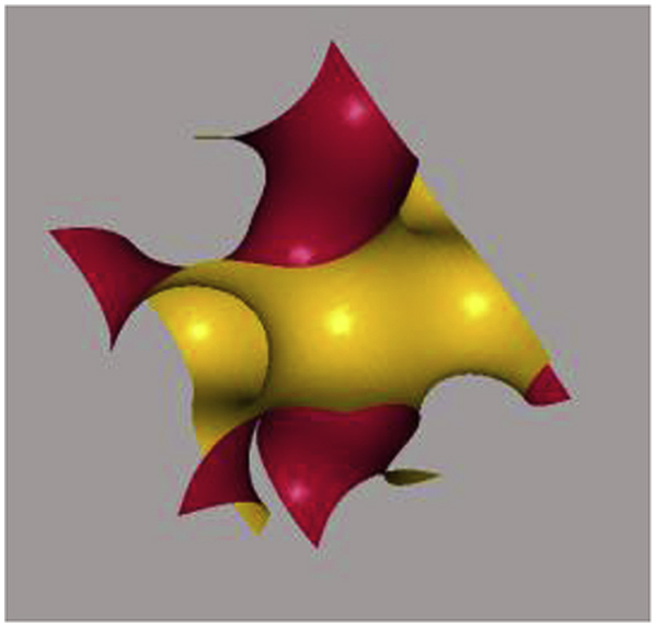
Gyroid surface following mathematical equation (3): in order to generate a basic unit cell of a gyroid surface, the x, y and z spatial directions are in the interval length of 2π, where x, y, z = [-π, π] and .
Fig. 9.
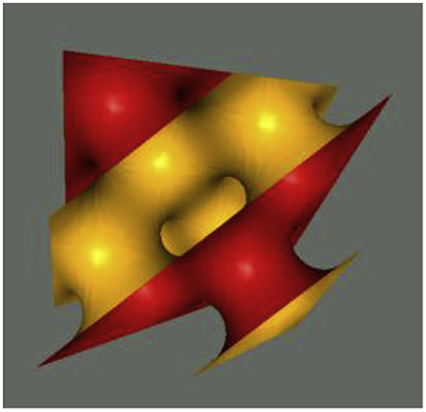
Diamond surface following mathematical equation (4): in order to generate a basic unit cell of a diamond surface, the x, y and z spatial directions are in the interval length of 2π, where x, y, z = [-π, π] and .
Previous studies investigated the mechanical properties of TPMS architectures [20,31,106,123,125] in which powder bed fusion fabrication methods (SLS, SLM and EBM) were employed to build up metallic TPMS structures, especially for Ti and its alloys (see Table 3). These AM methods address the challenges of conventional manufacturing processes, allowing the fabrication of complex, open-cellular TPMS architectures. TPMS porous structures and scaffolds possess great bio-mimicry features and excellent mechanical property, which improves implant feasibility and reliability. According to Rajagopalan et al. [126], the ideal biomorphic geometry would be a structure with surfaces that are continuous through space and separated into two not-necessarily-equal sub-spaces by a non-intersecting, two-sided surface. TPMS geometries exhibit great biomorphic features with smooth continuous surfaces along three independent directions and the surfaces divide the structure into two non-intersecting spaces. Compared to the straight edges or sharp turns of geometrically primitive's shapes such as cylinders and cubes, TPMS structures can provide a better biomorphic environment for cell activities such as cell attachment, penetration, migration and proliferation [123,126]. In addition, TPMS structures were also reported to exhibit good fatigue properties because of the curvature of the struts; at the nodal points, the stress concentrations caused by defects were eliminated [117,119,127]. During the fabrication process, a TMPS structure has better manufacturability than a structure with sharp turns or straight-edged pores and struts, eliminating the issue of thermal deformation caused by long overhangs [128].
Table 3.
Mechanical properties and porosity of SLM/EBM fabricated Ti—6Al—4V/CP-Ti TPMS architectures and human cortical and trabecular bone.
| Structure (Scaffolds) | Porosity (Volume fraction %) | Material | Unit cell size (mm) | Elastic modulus (GPa) | Pore size (mm) | Methods | Yield strength (MPa) | References |
|---|---|---|---|---|---|---|---|---|
| Gyroid | 80–95 | Ti—6Al—4V | 3–7 | 0.13±0.02–1.25±0.04 | 0.56–1.6 | SLM | 6.5010.62–81.302.60 | [123] |
| Gyroid | 5–10 | Ti—6Al—4V | 17.45–19.14 (Predicted) | – | 1342-1581 (Predicted) | [123] | ||
| Diamond | 80–95 | Ti—6Al—4V | 3–7 | 0.12±0.03–1.25±0.07 | 0.48–1.45 | SLM | 4.662±0.13–69.21±4.22 | [123] |
| Diamond | 5–10 | Ti—6Al—4V | 15.73–17.19 (predicted) | 1403-1559 (Predicted) | [123] | |||
| Gyroid | – | Ti—6Al—4V | 2.5–4 | 0.5912–0.7 | – | EBM | 1.69–13.19 | [31] |
| Gyroid | 82 | Ti—6Al—4V | 2 | 0.637–1.084 | 1.85–0.6 | EBM | 13.18–19.20 | [20] |
| Gyroid | 84.5 | Ti—6Al—4V | 2.5 | 0.842–1.060 | 1.24–0.88 | EBM | 15.53–17.35 | [20] |
| Gyroid | 85 | Ti—6Al—4V | 3 | 0.839–0.824 | 1.5–1.47 | EBM | 14.05–15 | [20] |
| Gyroid | 68.7 | CP—Ti (grade 1) | 2 | 2.017–2.676 | 1.24±0.1 | SLM | 51.6–54.5 | [106] |
| Gyroid | 73.3 | CP—Ti (grade 1) | 2.5 | 2.107–2.170 | 1.66±0.1 | SLM | 44.9–56.5 | [106] |
| Gyroid | 72.4 | CP—Ti (grade 1) | 3 | 1.465–2.302 | 1.91±0.1 | SLM | 49.0–53.3 | [106] |
| Cortical bone | 5–10 | Human bones | 7.7–21.8 | 103–222 | [20,106,123,124] | |||
| Trabecular bone | 50–90 | Human bones | 0.0224–0.132.32 | 0.8–11.6 | [ [21,106,123,124]] |
4.2. Popular TPMS structure -- gyroid
The most popular TPMS architectural shape for biomedical applications is the gyroid minimal structure, discovered by Schoen in 1970 [129,130]. Researchers have experimentally shown that the gyroid architecture is suitable for biomorphic scaffold design in tissue engineering [112]. Recently, extensive research has been carried out on analysis of the mechanical properties of open-cellular gyroid structures. From the morphological perspective, TPMS architectures are generally categorized into two types, minimal surface network solids and minimal surface sheet solids, which can also be applied to gyroid surface structures [[131], [132], [133]]. Both structures are established from gyroid surfaces and are distinguished by the number of void spaces. A network-based gyroid structure is a solid structure with a single void domain, whereas a sheet-based gyroid structure has two partitioned, unconnected void spaces. Kapfer et al. [131] demonstrated that the sheet-based gyroid structure has higher stiffness than the network-based gyroid structure at the same porosity of the same material. Similarly, Al-Ketan et al. [133] investigated the mechanical properties of a wide range of structures, including strut-based, skeletal-TPMS and sheet-TPMS porous structures, and concluded that sheet-TPMS structures have superior mechanical properties in terms of stress and strain responses (Young's modulus). Sheet-based gyroid structures also have relatively higher Young's modulus, peak stress, and toughness in comparison with skeletal gyroid structures (see Fig. 10).
Fig. 10.

3D CAD gyroid unit cells: (a) 3 mm sheet solid gyroid unit cell with 0.3 mm offset thickness and (b) 3 mm network solid gyroid unit cell at 50% volume fraction.
Although sheet solid gyroid structure shows good mechanical performance, unconnected porous structure could be a serious disadvantage. As mentioned earlier, good pore interconnectivity is essential for scaffold design because the interconnected space supports body fluid transport, facilitates vascularization, cells activities and tissue ingrowth [39,94]. Sheet solid gyroid structure displays unconnected pores thus is not preferred by researchers in the field of tissue engineering. Compared with sheet solid gyroid structure, network solid gyroid structure also provides excellent mechanical properties. More importantly, the pores are interconnected and their volume fraction is controllable. This makes the structure more reliable and practical for orthopedic implant applications (see Fig. 11).
Fig. 11.

A block of a 3D CAD gyroid scaffold in different views (constituted by 3 mm network solid gyroid unit cell).
The abovementioned equation (5) can be extended as:
| (9) |
where L is a variable determining the size of unit cell's edge length. Offset determines the volume fractions of the unit cell, enabling the adjustment of porosities between 50% and 90% [114,134]. The volume fraction of a gyroid unit cell is 50% when = 0. With an increase in the absolute offset value, the relative density of a gyroid structure decreases and the porosity increases. Fig. 12(a–f) show the gyroid surfaces and network based on gyroid unit cell with different α values. In Fig. 12(c), the porosity of the gyroid structure is 70% when = −0.6. According to Dawei et al. [114], when the absolute value of = 1.41, the gyroid structure exhibits the maximum porosity of 90% and becomes a ‘pinch-off’ phase (Fig. 12(e)), which causes geometric discontinuity problems. This gyroid structure becomes fragile and losses its mechanical properties, and the manufacturability of such structures also decreases. When the absolute value of > 1.41, the struts of the gyroid structure collapse into eight small parts and all parts are disconnected (Fig. 12(f-g)). In addition, the absolute value can not be great than 1.5 as the gyroid will disappear [114].
Fig. 12.

Gyroid surfaces and network-based on gyroid unit cell with different offset (α) values: (a) a 3 mm network-based gyroid structure in an 3 × 3 × 3 mm cubic; (b-1) gyroid surface without offset, (b-2) network-based gyroid unit cell without offset, (c-1) gyroid surface with offset = −0.6, (c-2) network-based gyroid unit cell with offset = −0.6, (d-1) gyroid surface with offset = −1.31, (d-2) network-based gyroid with offset = −1.31, (e) gyroid surface with offset = −1.41, (f) gyroid surface with offset = −1.42, (g) gyroid surface with offset = −1.49.
4.3. Normal gyroids and deformed gyroids
In order to improve the mechanical performance of the gyroid structures, the gyroid pore shape can be modified to be the deformed gyroids. The normal gyroid architecture is associate with spherical pores, where the angle between the strut and the axial direction is 45°. A deformed gyroid exhibits ellipsoidal-shaped pores with the variable radius in the direction of the longitudinal axis. Fig. 13 shows the schematic of a normal pore and a deformed pore. Both gyroid structures have shown a good strength-to-weight ratio for a certain angle of strut orientation and specific strength and stiffness [135,136]. Yanez et al. [31,135] investigated the mechanical properties of a normal gyroid scaffold and a severally deformed gyroid scaffold with different angels (19°, 21.5°, 26°, 35°, 55°, 64° and 68.5°) in terms of compression tests, torsion tests and finite element analysis and reported that both the elastic modulus and compressive strength of the gyroid structures were reversely proportional to the strut angle at the axial direction. As the pores of normal gyroid exhibit a spherical shape, the structure possesses higher homogeneity in mechanical performance than that of the deformed gyroid. An optimization of gyroid structure to support different types of loads at different directions might be a suitable solution for the reconstruction of bone defects in the human body [31].
Fig. 13.

Schematic of a normal pore and a deformed pore.
5. Conclusions
In summary, this paper has reviewed the current technologies for open-cellular structural design for metal implant applications. The fundamental requirements of metal implants, porosity, fabrication methods and TPMS have been discussed. The main conclusions are as follows:
-
(1)
Metallic orthopedic implants must satisfy certain criteria to protect patients from biocompatibility and mechanical risks. On the one hand, implants need to be accepted by the human body, ensuring cells live in a safe and supportive environment for their activities. On the other hand, mechanical damage or failure caused by stress-shielding needs to be avoided. An implant needs to have an appropriate elastic modulus to match that of natural bone.
-
(2)
A well-designed porous structure is beneficial for cell activities such as attachment and proliferation, which facilitate new bone formation and regeneration. In addition, porosity is a parameter that can be used to adjust the mechanical properties of the designed structures, in terms of both strength and Young's modulus. In the case of temporary metal implants, porosity plays a vital role in determining the corrosion rate, due to the change in the surface area.
-
(3)
One of the advanced AM methods, the powder bed fusion technique, has great potential for metal implant fabrication, and can be used to manufacture high-quality metallic models. The sub-classes of the powder bed fusion method, SLS, SLM and EBM, have been applied to implant fabrication in biomedical and biomaterial studies.
-
(4)
Implant structures with TPMS are drawing researching attention. These novel structures, such as gyroid structure, exhibit great bio-mimicry features to support cell activity and also provide superior mechanical properties.
Acknowledgements
The authors acknowledge the financial support for this research by the Australian Research Council through the Discovery Projects DP170102557 and DP180100762.
Footnotes
Peer review under responsibility of KeAi Communications Co., Ltd.
References
- 1.Goudie E.B., Robinson C., Walmsley P., Brenkel I. Changing trends in total knee replacement. Eur. J. Orthop. Surg. Traumatol. 2017;27:539–544. doi: 10.1007/s00590-017-1934-8. [DOI] [PMC free article] [PubMed] [Google Scholar]
- 2.Losina E., Katz J.N. Total knee arthroplasty on the rise in younger patients: are we sure that past performance will guarantee future success. Arthritis Rheum. 2012;64:339–341. doi: 10.1002/art.33371. [DOI] [PMC free article] [PubMed] [Google Scholar]
- 3.Prasad K., Bazaka O., Chua M., Rochford M., Fedrick L., Spoor J., Symes R., Tieppo M., Collins C., Cao A., Markwell D., Ostrikov K., Bazaka K. Metallic biomaterials: current challenges and opportunities. Materials. 2017;10:884. doi: 10.3390/ma10080884. [DOI] [PMC free article] [PubMed] [Google Scholar]
- 4.Palmer L.C., Newcomb C.J., Kaltz S.R., Spoerke E.D., Stupp S.I. Biomimetic systems for hydroxyapatite mineralization inspired by bone and enamel. Chem. Rev. 2008;108:4754–4783. doi: 10.1021/cr8004422. https://pubs.acs.org/doi/abs/10.1021/cr8004422 [DOI] [PMC free article] [PubMed] [Google Scholar]
- 5.Goods Administration Therapeutic. 2011. Australian Regulatory Guidelines for Medical Devices.https://www.tga.gov.au/sites/default/files/devices-argmd-01.pdf [Google Scholar]
- 6.Therapeutic Goods (Medical Devices) Regulations 2002. 2002. https://www.legislation.gov.au/Details/F2018C00490 Statutory Rules No. 236. [Google Scholar]
- 7.Science Learning Hub, Toxicity. 2009. https://www.sciencelearn.org.nz/resources/1540-toxicity [Google Scholar]
- 8.Department of health . 2013. What You Know Can Help You - an Introduction to Toxic Substances.https://www.health.ny.gov/environmental/chemicals/toxic_substances.htm [Google Scholar]
- 9.Jaishankar M., Tseten T., Anbalagan N., Mathew B.B., Beeregowda K.N. Toxicity, mechanism and health effects of some heavy metals. Interdiscipl. Toxicol. 2014;7:60–72. doi: 10.2478/intox-2014-0009. [DOI] [PMC free article] [PubMed] [Google Scholar]
- 10.Chen Q., Thouas G.A. Metallic implant biomaterials. Mater. Sci. Eng. R Rep. 2015;87:1–57. doi: 10.1016/j.mser.2014.10.001. [DOI] [Google Scholar]
- 11.Plum L.M., Rink L., Haase H. The essential toxin: impact of zinc on human health. Int. J. Environ. Res. Publ. Health. 2010;7:1342–1365. doi: 10.3390/ijerph7041342. [DOI] [PMC free article] [PubMed] [Google Scholar]
- 12.Egorova K.S., Ananikov V.P. Toxicity of metal compounds: knowledge and myths. Organometallics. 2017;36:4071–4090. https://pubs.acs.org/doi/full/10.1021/acs.organomet.7b00605 [Google Scholar]
- 13.Williams D.F. There is no such thing as a biocompatible material. Biomaterials. 2014;35:10009–10014. doi: 10.1016/j.biomaterials.2014.08.035. [DOI] [PubMed] [Google Scholar]
- 14.O'Brien F.J. Biomaterials & scaffolds for tissue engineering. Mater. Today. 2011;14:88–95. doi: 10.1016/S1369-7021(11)70058-X. [DOI] [Google Scholar]
- 15.Little N., Rogers B., Flannery M. Bone formation, remodeling and healing. Surgery. 2011;29:141–145. doi: 10.1016/j.mpsur.2011.01.002. [DOI] [Google Scholar]
- 16.Terrier C.S., Gasque P. Bone responses in health and infectious diseases: a focus on osteoblasts. J. Infect. 2017;75:281–292. doi: 10.1016/j.jinf.2017.07.007. [DOI] [PubMed] [Google Scholar]
- 17.Bundy K.L. 2008. Biomaterials and the Chemical Environment of the Body, Joint Replacement Technology; pp. 56–80. [DOI] [Google Scholar]
- 18.Armas L.A.G., Lappe J.M., Heaney R.P. Chapter 19 - calcium, bone strength and fractures. Osteopor. Men. 2010:235–241. doi: 10.1016/B978-0-12-374602-3.00019-5. [DOI] [Google Scholar]
- 19.Biesiekierski A., Wang J., Gepreel M.A., Wen C. A new look at biomedical Ti-based shape memory alloys. Acta Biomater. 2012;8:1661–1669. doi: 10.1016/j.actbio.2012.01.018. [DOI] [PubMed] [Google Scholar]
- 20.Ataee A., Li Y., Fraser D., Song G., Wen C. Anisotropic Ti-6Al-4V gyroid scaffolds manufactured by electron beam melting (EBM) for bone implant applications. Mater. Des. 2018;137:345–354. doi: 10.1016/j.matdes.2017.10.040. [DOI] [Google Scholar]
- 21.Poumarat G., Squire P. Comparison of mechanical properties of human, bovine bone and a new processed bone xenograft. Biomaterials. 1993;14:337–340. doi: 10.1016/0142-9612(93)90051-3. [DOI] [PubMed] [Google Scholar]
- 22.Moravej M., Mantovani D. Biodegradable metals for cardiovascular stent application: interests and new opportunities. Int. J. Mol. Sci. 2011;12:4250–4270. doi: 10.3390/ijms12074250. [DOI] [PMC free article] [PubMed] [Google Scholar]
- 23.Wen P., Jauer L., Voshage M., Chen Y., Poprawe R., Schleifenbaum J.H. Densification behavior of pure Zn metal parts produced by selective laser melting for manufacturing biodegradable implants. J. Mater. Process. Technol. 2018;258:128–137. doi: 10.1016/j.jmatprotec.2018.03.007. [DOI] [Google Scholar]
- 24.Hou Y., Jia G., Yue R., Chen C., Pei J., Zhang H., Huang H., Xiong M., Yuan G. Synthesis of biodegradable Zn-based scaffolds using NaCl templates: relationship between porosity, compressive properties and degradation behavior. Mater. Char. 2018;137:162–169. doi: 10.1016/j.matchar.2018.01.033. [DOI] [Google Scholar]
- 25.Katarivas Levy G., Goldman J., Aghion E. The prospects of zinc as a structural material for biodegradable implants—a review paper. Metals. 2017;7:402. doi: 10.3390/met7100402. [DOI] [Google Scholar]
- 26.Li H., Zheng Y., Qin L. Progress of biodegradable metals. Prog. Nat. Sci.: Mater. Int. 2014;24:414–422. doi: 10.1016/j.pnsc.2014.08.014. [DOI] [Google Scholar]
- 27.Zheng Y.F., Gu X.N., Witte F. Biodegradable metals. Mater. Sci. Eng. R Rep. 2014;77:1–34. doi: 10.1016/j.mser.2014.01.001. [DOI] [Google Scholar]
- 28.Bowen P.K., Drelich J., Goldman J. Zn exhibits ideal physiological corrosion behavior for bioabsorbable stents. Adv. Mater. 2013;25:2577–2582. doi: 10.1002/adma.201300226. [DOI] [PubMed] [Google Scholar]
- 29.Li Y., Jahr H., Lietaert K., Pavanram P., Yilmaz A., Fockaert L.I., Leeflang M.A., Pouran B., Gonzalez-Garcia Y., Weinans H., Mol J.M.C., Zhou J., Zadpoor A.A. Additively manufactured biodegradable porous iron. Acta Biomater. 2018;77:380–393. doi: 10.1016/j.actbio.2018.07.011. [DOI] [PubMed] [Google Scholar]
- 30.Carlos A., Leon Leon y. New perspectives in mercury porosimetry. Adv. Colloid Interface Sci. 1998;76–77:341–372. [Google Scholar]
- 31.Yánez A., Cuadrado A., Martel O., Afonso H., Monopoli D. Gyroid porous titanium structures: a versatile solution to be used as scaffolds in bone defect reconstruction. Mater. Des. 2018;140:21–29. doi: 10.1016/j.matdes.2017.11.050. [DOI] [Google Scholar]
- 32.Karageorgiou V., Kaplan D. Porosity of 3D biomaterial scaffolds and osteogenesis. Biomaterials. 2005;26:5474–5491. doi: 10.1016/j.biomaterials.2005.02.002. [DOI] [PubMed] [Google Scholar]
- 33.Kaplan F.S., Hayes W.C., Keaveny T.M., Boskey A., Einhorn T.A., Iannotti J.P. American Academy of Orthopaedic Surgeons; 1994. Form and Function of Bone, Orthopaedic Basic Science; pp. 128–184. [Google Scholar]
- 34.Keaveny T.M., Morgan E.F., Niebur G.L., Yeh O.C. Biomechanics of trabecular bone. Annu. Rev. Biomed. Eng. 2001;3:307–333. doi: 10.1146/annurev.bioeng.3.1.307. https://www.annualreviews.org/doi/abs/10.1146/annurev.bioeng.3.1.307 [DOI] [PubMed] [Google Scholar]
- 35.Renders G.A.P., Mulder L., J van Ruijven L., van Eijden T.M.G.J. Porosity of human mandibular condylar bone. J. Anat. 2010;3:239–248. doi: 10.1111/j.1469-7580.2007.00693.x. [DOI] [PMC free article] [PubMed] [Google Scholar]
- 36.Wieding J., Lindner T., Bergschmidt P., Bader R. Biomechanical stability of novel mechanically adapted open-porous titanium scaffolds in metatarsal bone defects of sheep. Biomaterials. 2015;46:35–47. doi: 10.1016/j.biomaterials.2014.12.010. [DOI] [PubMed] [Google Scholar]
- 37.Wieding J., Jonitz A., Bader R. The effect of structural design on mechanical properties and cellular response of additive manufactured titanium scaffolds. Materials. 2012;5:1336–1347. doi: 10.3390/ma5081336. [DOI] [Google Scholar]
- 38.Kuboki Y., Takita H., Kobayashi D., Tsuruga E., Inoue M., Murata M. BMP-induced osteogenesis on the surface of hydroxyapatite with geometrically feasible and nonfeasible structures: topology of osteogenesis. J. Biomed. Mater. Res. 1998;39:190–199. doi: 10.1002/(SICI)1097-4636(199802)39:2%3c190::AID-JBM4%3e3.0.CO;2-K. [DOI] [PubMed] [Google Scholar]
- 39.Chen Q., Bretcanu O., Boccaccini A.R. Inorganic and composite bioactive scaffolds for bone tissue engineering. In: Chu P.K., Liu X., editors. Biomaterials Fabrication and Processing Handbook. CRC Press; 2008. [Google Scholar]
- 40.Vahidgolpayegani A., Wen C., Hodgson P., Li Y. Metallic Foam Bone. 2017. 2 - production methods and characterization of porous Mg and Mg alloys for biomedical applications; pp. 25–82. [DOI] [Google Scholar]
- 41.Torres-Sanchez C., Al Mushref F.R.A., Norrito M., Yendall K., Liu Y., Conway P.P. The effect of pore size and porosity on mechanical properties and biological response of porous titanium scaffolds. Mater. Sci. Eng. C. 2017;77:219–228. doi: 10.1016/j.msec.2017.03.249. [DOI] [PubMed] [Google Scholar]
- 42.Woodard J.R., Hilldore A.J., Lan S.K., Park C.J., Morgan A.W., Eurell J.A.C., Clark S.G., Wheeler M.B., Jamison R.D., Wagoner Johnson A.J. The mechanical properties and osteoconductivity of hydroxyapatite bone scaffolds with multi-scale porosity. Biomaterials. 2007;28:45–54. doi: 10.1016/j.biomaterials.2006.08.021. [DOI] [PubMed] [Google Scholar]
- 43.Bose S., Roy M., Bandyopadhyay A. Recent advances in bone tissue engineering scaffolds. Trends Biotechnol. 2012;30:546–554. doi: 10.1016/j.tibtech.2012.07.005. [DOI] [PMC free article] [PubMed] [Google Scholar]
- 44.Hing K.A., Annaz B., Saeed S., Revell P.A., Buckland T. Microporosity enhances bioactivity of synthetic bone graft substitutes. J. Mater. Sci. Mater. Med. 2005;16:467–475. doi: 10.1007/s10856-005-6988-1. [DOI] [PubMed] [Google Scholar]
- 45.Ran Q., Yang W., Hu Y., Shen X., Yu Y., Xiang Y., Cai K. Osteogenesis of 3D printed porous Ti6Al4V implants with different pore sizes. Journal of the Mechanical Behavior of Biomedical Materials. 2018;84:1–11. doi: 10.1016/j.jmbbm.2018.04.010. [DOI] [PubMed] [Google Scholar]
- 46.van den Bogert A.J. Analysis and simulation of mechanical loads on the human musculoskeletal system: a methodological overview. Exerc. Sport Sci. Rev. 1994;22:23–51. [PubMed] [Google Scholar]
- 47.Ozan S., Lin J., Li Y., Ipek R., Wen C. Development of Ti-Nb-Zr alloys with high elastic admissible strain for temporary orthopedic devices. Acta Biomater. 2015;20:176–187. doi: 10.1016/j.actbio.2015.03.023. [DOI] [PubMed] [Google Scholar]
- 48.Biesiekierski A., Lin J., Munir K., Ozan S., Li Y., Wen C. Extraordinary high strength Ti-Zr-Ta alloys through nanoscaled, dual-cubic spinodal reinforcement. Acta Biomater. 2017;53:549–558. doi: 10.1038/s41598-018-24155-y. [DOI] [PubMed] [Google Scholar]
- 49.Biesiekierski A., Lin J., Li Y., Ping D., Yamabe-Mitarai Y., Wen C. Impact of ruthenium on mechanical properties, biological response and thermal processing of ß-type Ti-Nb-Ru alloys. Acta Biomater. 2017;48:461–467. doi: 10.1016/j.actbio.2016.09.012. [DOI] [PubMed] [Google Scholar]
- 50.Xu G., Kou H., Liu X., Li F., Li J., Zhou L. Microstructure and mechanical properties of porous titanium based on controlling Young's modulus. Rare Metal Mater. Eng. 2017;46:2041–2048. doi: 10.1016/S1875-5372(17)30176-5. [DOI] [Google Scholar]
- 51.Fousová M., Vojtěch D., Kubásek J., Jablonská E., Fojt J. Promising characteristics of gradient porosity Ti-6Al-4V alloy prepared by SLM process. Journal of the Mechanical Behavior of Biomedical Materials. 2017;69:368–376. doi: 10.1016/j.jmbbm.2017.01.043. [DOI] [PubMed] [Google Scholar]
- 52.Wen C., Mabuchi M., Yamada Y., Shimojima K., Chino Y., Asahina T. Processing of biocompatible porous Ti and Mg. Scripta Mater. 2001;45:1147–1153. [Google Scholar]
- 53.Wen C., Yamada Y., Shimojima K., Chino Y., Hosokawa H., Mabuchi M. Novel titanium foam for bone tissue engineering. J. Mater. Res. 2002;17:2633–2639. [Google Scholar]
- 54.Wen C., Yamada Y., Shimojima K., Chino Y., Asahina T., Mabuchi M. Processing and mechanical properties of autogenous titanium implant materials. J. Mater. Sci. Mater. Med. 2002;13:397–401. doi: 10.1023/a:1014344819558. [DOI] [PubMed] [Google Scholar]
- 55.Wen C., Yamada Y., Shimojima K., Chino Y., Hosokawa H., Mabuchi M. Compressibility of porous magnesium foam: dependency on porosity and pore size. Mater. Lett. 2004;58:357–360. [Google Scholar]
- 56.Gibson L.G., Ashby M.F. second ed. Cambridge University Press; Cambridge, U.K: 1997. Cellular Solids: Structure and Properties; p. 429. [Google Scholar]
- 57.Weißmann V., Bader R., Hansmann H., Laufer N. Influence of the structural orientation on the mechanical properties of selective laser melted Ti6Al4V open-porous scaffolds. Mater. Des. 2016;95:188–197. doi: 10.1016/j.matdes.2016.01.095. [DOI] [Google Scholar]
- 58.Yang L., Yan C., Fan H., Li Z., Cai C., Chen P., Shi Y., Yang S. Investigation on the orientation dependence of elastic response in Gyroid cellular structures. Journal of the Mechanical Behavior of Biomedical Materials. 2019;90:73–85. doi: 10.1016/j.jmbbm.2018.09.042. [DOI] [PubMed] [Google Scholar]
- 59.Kubásek J., Vojtěch D. Zn-based alloys as an alternative biodegradable material. Metals. 2012;5:1355–1361. [Google Scholar]
- 60.Redwood B. The advantages of 3D printing. https://www.3dhubs.com/knowledge-base/advantages-3d-printing 3D hubs.
- 61.Tang D., Tare R.S., Yang L.Y., Williams D.F., Ou K.L., Oreffo R.O.C. Biofabrication of bone tissue: approaches, challenges and translation for bone regeneration. Biomaterials. 2016;83:363–382. doi: 10.1016/j.biomaterials.2016.01.024. [DOI] [PubMed] [Google Scholar]
- 62.Javaid M., Haleem A. Additive manufacturing applications in orthopaedics: a review. J. Clin. Orthopaed Trauma. 2018;9:202–206. doi: 10.1016/j.jcot.2018.04.008. [DOI] [PMC free article] [PubMed] [Google Scholar]
- 63.Jardini A.L., Larosa M.A., Filho R.M., Zavaglia C.A.C., Bernardes L.F., Lambert C.S., Calderoni D.R., Kharmandayan P. Cranial reconstruction: 3D biomodel and custom-built implant created using additive manufacturing. J. Cranio-Maxillofacial Surg. 2014;42:1877–1884. doi: 10.1016/j.jcms.2014.07.006. [DOI] [PubMed] [Google Scholar]
- 64.Gokuldoss P.K., Kolla S., Eckert J. Additive manufacturing processes: selective laser melting, electron beam melting and binder jetting-selection guidelines. Materials. 2017;10:672. doi: 10.3390/ma10060672. https://doi:10.3390/ma10060672 [DOI] [PMC free article] [PubMed] [Google Scholar]
- 65.Hahnlen R., Dapino M.J. NiTi–Al interface strength in ultrasonic additive manufacturing composites. Compos. B Eng. 2014;59:101–108. [Google Scholar]
- 66.Hehr A., Dapino M.J. Interfacial shear strength estimates of NiTi-Al matrix composites fabricated via ultrasonic additive manufacturing. Compos. B Eng. 2015;77:199–208. doi: 10.1016/j.compositesb.2015.03.005. [DOI] [Google Scholar]
- 67.Additive Manufacturing Research Group, About Additive Manufacturing Powder Bed Fusion. http://www.lboro.ac.uk/research/amrg/about/the7categoriesofadditivemanufacturing/powderbedfusion/, (Accessed 3 July 2018).
- 68.Chia H.N., Wu B.M. Recent advances in 3D printing of biomaterials. J. Biol. Eng. 2015 doi: 10.1186/s13036-015-0001-4. [DOI] [PMC free article] [PubMed] [Google Scholar]
- 69.Sun S., Brandt M., Easton M. 2017. Powder Bed Fusion Processes: an Overview, Electronic and Optical Materials; pp. 55–77. [DOI] [Google Scholar]
- 70.El-Hajje A., Kolos E.C., Wang J.K., Maleksaeedi S., He Z., Wiria F.E., Choong C., Ruys A.J. Physical and mechanical characterisation of 3D-printed porous titanium for biomedical applications material science. Mater. Med. 2014;25:2471–2480. doi: 10.1007/s10856-014-5277-2. [DOI] [PubMed] [Google Scholar]
- 71.Laoui T., Santos E., Osakada K., Shiomi M., Morita M., Shaik S.K., Tolochko N.K., Abe F. Properties of titanium implant models made by laser processing. Proc. IME C J. Mech. Eng. Sci. 2006;6:857–863. doi: 10.1243/09544062JMES133. [DOI] [Google Scholar]
- 72.Ngo T.D., Kashani A., Imbalzano G., Nguyen K.T.Q., Hui D. Additive manufacturing (3D printing): a review of materials, methods, applications and challenges. Compos. B Eng. 2018;143:172–196. doi: 10.1016/j.compositesb.2018.02.012. [DOI] [Google Scholar]
- 73.Melchels F.P.W., Feijen J., Grijpma D.W. A review on stereolithography and its applications in biomedical engineering. Biomaterials. 2010;31:6121–6130. doi: 10.1016/j.biomaterials.2010.04.050. [DOI] [PubMed] [Google Scholar]
- 74.Chohan J.S., Singh R., Boparai K.S., Penna R., Fraternali F. Dimensional accuracy analysis of coupled fused deposition modeling and vapour smoothing operations for biomedical applications. Compos. B Eng. 2017;117:138–149. doi: 10.1016/j.compositesb.2017.02.045. [DOI] [Google Scholar]
- 75.Sood A.K., Ohdar R.K., Mahapatra S.S. Parametric appraisal of mechanical property of fused deposition modelling processed parts. Mater. Des. 2010;31:287–295. doi: 10.1016/j.matdes.2009.06.016. [DOI] [Google Scholar]
- 76.Mohamed O.A., Masood S.H., Bhowmik J.L. Optimization of fused deposition modeling process parameters: a review of current research and future prospects. Adv. Manufact. 2015;3:42–53. doi: 10.1007/s40436-014-0097-7. [DOI] [Google Scholar]
- 77.Tofail S.A.M., Koumoulos E.P., Bandyopadhyay A., Bose S., O'Donoghue L., Charitidis C. Additive manufacturing: scientific and technological challenges, market uptake and opportunities. Mater. Today. 2018;21:22–37. doi: 10.1016/j.mattod.2017.07.001. [DOI] [Google Scholar]
- 78.Bandyopadhyay A., Bose S., Das S. 3D printing of biomaterials. MRS Bull. 2015;40:108–115. [Google Scholar]
- 79.Lee H., Lim C.H.J., Low M.J., Tham N., Murukeshan V.M., Kim Y.J. Lasers in additive manufacturing: a review. Int. J. Precis. Eng. Manufact.-Green Technol. 2017;4:307–322. doi: 10.1007/s40684-017-0037-7. [DOI] [Google Scholar]
- 80.Manapat J.Z., Chen Q.Y., Ye P.R., Advincula R.C. 3D Printing of polymer nanocomposites via stereolithography. Macromol. Mater. Eng. 2017:1–13. doi: 10.1002/mame.201600553. [DOI] [Google Scholar]
- 81.Gibson I., Rosen D., Stucker B. Springer New York; New York, NY: 2015. Directed Energy Deposition Processes, Additive Manufacturing Technologies: 3D Printing, Rapid Prototyping, and Direct Digital Manufacturing; pp. 245–268. [Google Scholar]
- 82.Yeong W.Y., Sudarmadji N., Yu H.Y., Chua C.K., Leong K.F., Venkatraman S.S., Boey Y.C.F., Tan L.P. Porous polycaprolactone scaffold for cardiac tissue engineering fabricated by selective laser sintering. Acta Biomater. 2010;6:2028–2034. doi: 10.1016/j.actbio.2009.12.033. [DOI] [PubMed] [Google Scholar]
- 83.Kruth J.P., Vandenbroucke B., Vaerenbergh V.J., Mercelis P. Division PMA, Department of Mechanical Engineering; Katholieke Universiteit Leuven, Belgium: 2005. Benchmarking of Different SLS/SLM Processes as Rapid Manufacturing Techniques. [Google Scholar]
- 84.Liu Y., Yang Y., Mai S., Wang D., Song C. Investigation into spatter behavior during selective laser melting of AISI 316L stainless steel powder. Mater. Des. 2015;87:797–806. doi: 10.1016/j.matdes.2015.08.086. [DOI] [Google Scholar]
- 85.Shipley H., McDonnell D., Culleton M., Coull R., Lupoi R., O'Donnell G., Trimble D. Optimisation of process parameters to address fundamental challenges during selective laser melting of Ti-6Al-4V: a review. Int. J. Mach. Tool Manufact. 2018;128:1–20. doi: 10.1016/j.ijmachtools.2018.01.003. [DOI] [Google Scholar]
- 86.Bhavar V., Kattire P., Patil V., Khot S., Gujar K., Singh R. 4th Int. Conf. Exhib. Addit. Manuf. Technol. Banglore; India: 2014. A review on powder bed fusion technology of metal additive manufacturing. [Google Scholar]
- 87.Ardila L.C., Garciandia F., González-Díaz J.B., Álvarez P., Echeverria A., Petite M.M., Deffley R., Ochoa J. Effect of IN718 recycled powder reuse on properties of parts manufactured by means of selective laser melting. Phys. Procedia. 2014;56:99–107. doi: 10.1016/j.phpro.2014.08.152. [DOI] [Google Scholar]
- 88.Yan C., Hao L., Hussein A., Wei Q., Shi Y. Microstructural and surface modifications and hydroxyapatite coating of Ti-6Al-4V triply periodic minimal surface lattices fabricated by selective laser melting. Mater. Sci. Eng. C. 2017;75:1515–1524. doi: 10.1016/j.msec.2017.03.066. [DOI] [PubMed] [Google Scholar]
- 89.Sallica-Leva E., Jardini A.L., Fogagnolo J.B. Microstructure and mechanical behavior of porous Ti–6Al–4V parts obtained by selective laser melting. Journal of the Mechanical Behavior of Biomedical Materials. 2013;26:98–108. doi: 10.1016/j.jmbbm.2013.05.011. [DOI] [PubMed] [Google Scholar]
- 90.Larson R. Google Patents; 1994. Method and Device for Producing Three-dimensional Bodies. [Google Scholar]
- 91.Ataee A., Li Y., Song G., Wen C. 2017. Metal Scaffolds Processed by Electron Beam Melting for Biomedical Applications, Metallic Foam Bone; pp. 83–110. [DOI] [Google Scholar]
- 92.Arcam EBM, Electron Beam Melting– in the Forefront of Additive Manufacturing 2018: http://www.arcam.com/technology/electron-beam-melting/. (Accessed 7 July 2018).
- 93.Murr L.E., Gaytan S.M., Medina F., Lopez H., Martinez E., Machado B.I., Hernandez D.H., Martinez L., Lopez M.I., Wicker R.B., Bracke J. Next- generation biomedical implants using additive manufacturing of complex cellular and functional mesh arrays. Philos. Trans. R Soc. A Math. Phys. Eng. Sci. 2010;368:1999–2032. doi: 10.1098/rsta.2010.0010. [DOI] [PubMed] [Google Scholar]
- 94.Heinl P., Müller L., Körner C., Singer R.F., Müller F.A. Cellular Ti-6Al-4V structures with interconnected macro-porosity for bone implants fabricated by selective electron beam melting. Acta Biomater. 2008;4:1536–1544. doi: 10.1016/j.actbio.2008.03.013. [DOI] [PubMed] [Google Scholar]
- 95.Harrysson O.L.A., Cormier D.R. Software Conversion and Rapid Prototyping; 2006. Direct Fabrication of Custom Orthopedic Implants Using Electron Beam Melting Technology, Advanced Manufacturing Technology for Medical Applications: Reverse Engineering; pp. 191–206. [DOI] [Google Scholar]
- 96.Gong X., Anderson T., Chou K. Review on powder-based electron beam additive manufacturing technology. Manuf. Rev. 2014;1:507–515. doi: 10.1051/mfreview/2014001. [DOI] [Google Scholar]
- 97.Toh W.Q., Wang P., Tan X., Nai M.L.S., Liu E., Tor S.B. Microstructure and wear properties of electron beam melted Ti-6Al-4V Parts: a comparison study against as-cast form. Metals. 2016;6:284. doi: 10.3390/met6110284. [DOI] [Google Scholar]
- 98.Biamino S., Penna A., Ackelid U., Sabbadini S., Tassa O., Fino P., Pavese M., Gennaro P., Badini C. Electron beam melting of Ti-48Al-2Cr-2Nb alloy: microstructure and mechanical properties investigation. Intermetallics. 2010;19:776–781. doi: 10.1016/j.intermet.2010.11.017. [DOI] [Google Scholar]
- 99.Syam W.P., Al-Shehri H.A., Al-Ahmari A.M., Al-Wazzan K.A., Mannan M.A. Preliminary fabrication of thin-wall structure of Ti6Al4V for dental restoration by electron beam melting. Rapid Prototype. 2012;18:230–240. doi: 10.1108/13552541211218180. [DOI] [Google Scholar]
- 100.Luca F., Emanuele M., Pierfrancesco R., Alberto M. Microstructure and mechanical properties of Ti-6Al-4V produced by electron beam melting of pre-alloyed powders. Rapid Prototyp. 2009;15:171–178. doi: 10.1108/13552540910960262. [DOI] [Google Scholar]
- 101.Murr L.E., Gaytan S.M., Medina F., Martinez E., Martinez J.L., Hernandez D.H. Characterization of Ti-6Al-4V open cellular foams fabricated by additive manufacturing using electron beam melting. Mater. Sci. Eng. 2010;527:1861–1868. doi: 10.1016/j.msea.2009.11.015. [DOI] [Google Scholar]
- 102.Harun W.S.W., Kamariah M.S.I.N., Muhamad N., Ghani S.A.C., Ahmad F., Mohamed Z. A review of powder additive manufacturing processes for metallic biomaterials. Powder Technol. 2018;327:128–151. doi: 10.1016/j.powtec.2017.12.058. [DOI] [Google Scholar]
- 103.Bose S., Ke D., Sahasrabudhe H., Bandyopadhyay A. Additive manufacturing of biomaterials. Prog. Mater. Sci. 2018;93:45–111. doi: 10.1016/j.pmatsci.2017.08.003. [DOI] [PMC free article] [PubMed] [Google Scholar]
- 104.Krishna B.V., Bose S., Bandyopadhyay A. Low stiffness porous Ti structures for load-bearing implants. Acta Biomater. 2007;3:997–1006. doi: 10.1016/j.actbio.2007.03.008. [DOI] [PubMed] [Google Scholar]
- 105.Wu Y.C., Kuo C.N., Shie M.Y., Su Y.L., Wei L.J., Chen S.Y., Huang J.C. Structural design and mechanical response of gradient porous Ti-6Al-4V fabricated by electron beam additive manufacturing. Mater. Des. 2018;158:256–265. doi: 10.1016/j.matdes.2018.08.027. [DOI] [Google Scholar]
- 106.Ataee A., Li Y., Brandt M., Wen C. Ultrahigh-strength titanium gyroid scaffolds manufactured by selective laser melting (SLM) for bone implant applications. Acta Mater. 2018;158:354–368. doi: 10.1016/j.actamat.2018.08.005. [DOI] [Google Scholar]
- 107.Surmeneva M.A., Surmenev R.A., Chudinova E.A., Koptioug A., Tkachev M.S., Gorodzha S.N., Rännar L. Fabrication of multiple-layered gradient cellular metal scaffold via electron beam melting for segmental bone reconstruction. Mater. Des. 2017;133:195–204. doi: 10.1016/j.matdes.2017.07.059. [DOI] [Google Scholar]
- 108.Xin X.Z., Xiang N., Chen J., Wei B. In vitro biocompatibility of Co–Cr alloy fabricated by selective laser melting or traditional casting techniques. Mater. Lett. 2012;88:101–103. doi: 10.1016/j.matlet.2012.08.032. [DOI] [Google Scholar]
- 109.Demir A.G., Previtali B. Additive manufacturing of cardiovascular CoCr stents by selective laser melting. Mater. Des. 2017;119:338–350. doi: 10.1016/j.matdes.2017.01.091. [DOI] [Google Scholar]
- 110.Lord E.A., Mackay A.L., Ranganatan S. Cambridge University Press; 2006. New Geometry for New Materials. [Google Scholar]
- 111.Sychov M.M., Lebedev L.A., Dyachenko S.V., Nefedova L.A. Mechanical properties of energy-absorbing structures with triply periodic minimal surface topology. Acta Astronaut. 2017:1–4. doi: 10.1016/j.actaastro.2017.12.034. [DOI] [Google Scholar]
- 112.Yoo D.J. Porous scaffold design using the distance field and triply periodic minimal surface models. Biomaterials. 2011;32:7741–7754. doi: 10.1016/j.biomaterials.2011.07.019. [DOI] [PubMed] [Google Scholar]
- 113.Conan F. 3D-printed porous bed structures. Curr. Opin. Chem. Eng. 2017;18:10–15. doi: 10.1016/j.coche.2017.07.003. [DOI] [Google Scholar]
- 114.Li D., Liao W., Dai N., Dong G., Tang Y., Xie Y.M. Optimal design and modeling of gyroid-based functionally graded cellular structures for additive manufacturing. Comput. Aided Des. 2018;104:87–99. doi: 10.1016/j.cad.2018.06.003. [DOI] [Google Scholar]
- 115.Melchels F.P.W., Bertoldi K., Gabbrielli R., Velders A.H., Feijen J., Grijpma D.W. 2010. Mathematically Defined Tissue Engineering Scaffold Architectures Prepared by Stereolithography Biomaterials; pp. 6909–6916. 31. [DOI] [PubMed] [Google Scholar]
- 116.K3dsurf. http://k3dsurf.sourceforge.net/, (Accessed 1 May 2018).
- 117.Speirs M., Van Hooreweder B., Van Humbeeck J., Kruth J.P. Fatigue behaviour of NiTi shape memory alloy scaffolds produced by SLM, a unit cell design comparison. Journal of the Mechanical Behavior of Biomedical Materials. 2016;70:53–59. doi: 10.1016/j.jmbbm.2017.01.016. [DOI] [PubMed] [Google Scholar]
- 118.Bobbert F.S.L., Lietaert K., Eftekhari A.A., Pouran B., Ahmadi S.M., Weinans H., Zadpoor A.A. Additively manufactured metallic porous biomaterials based on minimal surfaces: a unique combination of topological, mechanical, and mass transport properties. Acta Biomater. 2017;53:572–584. doi: 10.1016/j.actbio.2017.02.024. [DOI] [PubMed] [Google Scholar]
- 119.Femmer T., Alexander J.C.K., Wessling M. Estimation of the structure dependent performance of 3-D rapid prototyped membranes. Chem. Eng. J. 2015;273:438–445. doi: 10.1016/j.cej.2015.03.029. [DOI] [Google Scholar]
- 120.Nguyen B.D., Jeong Y.C., Kang K. Design of the P-surfaced shellular, an ultra-low density material with micro-architecture. Comput. Mater. Sci. 2017;139:162–178. doi: 10.1016/j.commatsci.2017.07.025. [DOI] [Google Scholar]
- 121.Almeida H.A., Bartolo P.J. Design of tissue engineering scaffolds based on hyperbolic surfaces: structural numerical evaluation. Med. Eng. Phys. 2014;36:1033–1040. doi: 10.1016/j.medengphy.2014.05.006. [DOI] [PubMed] [Google Scholar]
- 122.Gómez S., Vlad M.D., López J., Fernández E. Design and properties of 3D scaffolds for bone tissue engineering. Acta Biomater. 2016;42:341–350. doi: 10.1016/j.actbio.2016.06.032. [DOI] [PubMed] [Google Scholar]
- 123.Yan C., Hao L., Hussein A., Young P. Ti–6Al–4V triply periodic minimal surface structures for bone implants fabricated via selective laser melting. Mech. Behav. Biomed. Mater. 2015;51:61–73. doi: 10.1016/j.jmbbm.2015.06.024. [DOI] [PubMed] [Google Scholar]
- 124.Sikavitsas V.I., Temenoff J.S., Mikos A.G. Biomaterials and bone mechanotransduction. Biomaterials. 2001;22:2581–2593. doi: 10.1016/S0142-9612(01)00002-3. [DOI] [PubMed] [Google Scholar]
- 125.Al-Ketan O., Al-Rub R.K.A., Rowshan R. Mechanical properties of a new type of architected interpenetrating phase composite materials. Adv. Mater. Technol. 2017;2 doi: 10.1002/admt.201600235. [DOI] [Google Scholar]
- 126.Rajagopalan S., Robb R.A. Schwarz meets Schwann: design and fabrication of biomorphic and durataxic tissue engineering scaffolds. Med. Image Anal. 2006;10:693–712. doi: 10.1016/j.media.2006.06.001. [DOI] [PubMed] [Google Scholar]
- 127.Yoo D.J., Kim K.H. An advanced multi-morphology porous scaffold design method using volumetric distance field and beta growth function. Int. J. Precis. Eng. Manuf. 2015;16:2021–2032. doi: 10.1007/s12541-015-0263-2. [DOI] [Google Scholar]
- 128.Yan C.Z., Hao L., Hussein A., Raymont D. Evaluations of cellular lattice structures manufactured using selective laser melting. Int. J. Mach. Tool Manufact. 2012;62:32–38. doi: 10.1016/j.ijmachtools.2012.06.002. [DOI] [Google Scholar]
- 129.Scheon A.H. Reflections concerning triply-periodic minimal surfaces. Interf. Focus. 2012;2:658–668. doi: 10.1098/rsfs.2012.0023. [DOI] [PMC free article] [PubMed] [Google Scholar]
- 130.Schoen A.H. National Aeronautics and Space Administration (NASA) Tech; Washington, DC: 1970. Infinite Periodic Minimal Surfaces without Self-intersection. Note no. D-5541. [Google Scholar]
- 131.Kapfer S.C., Hyde S.T., Mecke K., Arns C.H., Schroder-Turk G.E. Minimal surface scaffold designs for tissue engineering. Biomaterials. 2011;32:6875–6882. doi: 10.1016/j.biomaterials.2011.06.012. [DOI] [PubMed] [Google Scholar]
- 132.Maskery I., Aboulkhair N.T., Aremu A., Tuck C., Ashcroft I. Compressive failure modes and energy absorption in additively manufactured double gyroid lattices. Add. Manufact. 2017;16:24–29. doi: 10.1016/j.addma.2017.04.003. [DOI] [Google Scholar]
- 133.Al-Ketan O., Rowshan R., Abu Al-Rub R.K. Topology-mechanical property relation- ship of 3D printed strut, skeletal, and sheet based periodic metallic cellular materials. Add. Manufact. 2018;19:167–183. doi: 10.1016/j.addma.2017.12.006. [DOI] [Google Scholar]
- 134.K. Monkova, P. Monka, I. Zetkova, P. Hanzl, D. Mandulak, Three approaches to the gyroid structure modelling as a base of lightweight component produced by additive technology, 2017 2nd International Conference on Computational Modeling, Simulation and Applied Mathematics.
- 135.Yánez A., Herrera A., Martel O., Monopoli D., Afonso H. Compressive behaviour of gyroid lattice structures for human cancellous bone implant applications. Mater. Sci. Eng. C. 2016;68:445–448. doi: 10.1016/j.msec.2016.06.016. [DOI] [PubMed] [Google Scholar]
- 136.Challis V.J., Xu X., Zhang L.C., Roberts A.P., Grotowski J.F., Sercombe T.B. High specific strength and stiffness structures produced using selective laser melting. Mater. Des. 2014;63:783–788. doi: 10.1016/j.matdes.2014.05.064. [DOI] [Google Scholar]