



Abstract

Skin wound healing is a major health care issue. While electric stimulations have been known for decades to be effective for facilitating skin wound recovery, practical applications are still largely limited by the clumsy electrical systems. Here, we report an efficient electrical bandage for accelerated skin wound healing. On the bandage, an alternating discrete electric field is generated by a wearable nanogenerator by converting mechanical displacement from skin movements into electricity. Rat studies demonstrated rapid closure of a full-thickness rectangular skin wound within 3 days as compared to 12 days of usual contraction-based healing processes in rodents. From in vitro studies, the accelerated skin wound healing was attributed to electric field-facilitated fibroblast migration, proliferation, and transdifferentiation. This self-powered electric-dressing modality could lead to a facile therapeutic strategy for nonhealing skin wound treatment.
Keywords: wound healing, physical therapy, nanogenerator, wearable device, self-powering
Nonhealing skin wounds, such as diabetic foot ulcers, venous-related ulcerations, and nonhealing surgical wounds affect more than 6.5 million people in the United States and result in enormous health care expenditures, with the total cost estimated at more than $25 billion per year.1−4 In addition, slow- or nonhealing skin wounds are morbid conditions that can result in long-term physical and mental suffering due to the protracted treatment courses often required by chronic wounds. The principal goal in skin wound management is to achieve rapid wound closure. Treating skin wounds has been dated to the very early stage of human civilization, e.g., by making plasters and bandaging the wounds.5 Owing to the large advancements of modern biomedicine and medical technology, the last several decades have seen the evolution of a number of more effective treatment strategies, including invasive methods such as wound debridement6 and noninvasive techniques such as compression bandaging,7 wound dressing,8,9 hyperbaric oxygen therapy,10 negative pressure therapy,11 ultrasound,12 and electrical stimulation.13,14 Most of these methods are passive treatments and rarely participate in controlling endogenous cell behaviors. Currently, advanced growth factors-mediated therapy emerged as an effective approach for regenerative skin wound healing, which still faces the challenges of rapid degradation and loss of bioactivity.15,16 Electrical stimulation (ES) for wound healing is an attractive adjunct to wound care. It imitates the natural wound-healing mechanism of the endogenous electric field to facilitate skin growth. It has the potential to treat many different types of acute and chronic skin wounds with minimal adverse effects and good simplicity to apply.
The therapeutic effects of ES for wound healing were first observed in the late 20th century.17,18 It is believed that an electric field is essential for directing many cellular processes that lead to orderly healing naturally.19,20 As summarized in the literature,21 ES can decrease edema around the electrode; lyse or liquify necrotic tissue; stimulate growth of granulation tissue; increase blood flow; cause fibroblasts to proliferate and make collagen; induce epidermal cell migration; attract neutrophils; stimulate neurite growth directionally; promote epithelial growth and organization; decrease mast cells in healing wounds; attract macrophages; and stimulate receptor sites to accept certain growth factors. Although the influence from an electric field can be significant, clinical applications of electrical stimulation for wound healing typically involves large-sized extracorporeal devices to provide appropriate electrical fields and may require patient hospitalization.
The recent innovation of nanogenerator (NG) technology opened a route for generating periodic biphasic electric pulses by locally converting mechanical displacements, such as body or muscle motions.22−27 This exceptional capability makes NG a candidate for producing electrical stimulations that is self-sustainable and biologically responsive. Besides, NGs could be made flexible with reasonably high output power density and energy conversion efficiency. Their multiple energy conversion mechanisms, including both piezoelectric and triboelectric effects, allow a wide selection of materials and multiple designs principles. Furthermore, typical NGs have been proved fairly stable against environmental conditions like temperature28 and humidity29,30 within the range of normal biological systems. Therefore, NG may bring opportunities for electrical stimulation-based medical treatments. In this work, we report a significantly accelerated skin wound recovery under the influence of small electrical pulses produced by a wearable NG device. The wound-healing time on rat’s dorsal skin was reduced from 12 days to less than 3 days by this treatment, which was superior to most other reported wound recovery strategies. The outstanding effectiveness of the self-activated electrotherapy was attributed to electric field-facilitated fibroblast migration, proliferation, and transdifferentiation.
Results and Discussion
The self-activated electrotherapy bandage device consisted of two parts: the biomechanical energy conversion part (i.e., NG) and the dressing electrodes. As shown in Figure 1a, the NG was made by overlapping the Cu/PTFE (electronegative material) layer with another Cu (electropositive material) layer on different sides of the polyethylene terephthalate (PET) substrate. The PTFE layer can slide back and forth relative to the Cu layer. Owing to the good flexibility of PTFE (Young’s Modulus is 0.5 GPa), the multilayer device (PET–Cu foil–PTFE) showed a much lower bending modulus compared to pure PET films (Figure 1b), demonstrating good adaptability to soft skin surface. This NG design worked appropriately under regular sliding conditions, and its voltage, current, and power output under different load resistance are included in the Supporting Information (Figure S2). The toxicity of the bandage was evaluated by measuring the cell viability of 3T3 fibroblasts cultured on PTFE and PET surfaces using the MTT assay.31 Results up to 72 h showed that both PET and PTEF surfaces had negligible impacts on the cell viability (Figure 1c), meaning they are safe to be applied to the wounds.
Figure 1.

NG-based bandage and potential wound-healing application. (a) Schematic image of NG configuration. The digital image of NG is shown below. (b) Bending modulus of PET, PET–Cu foil, and PET–Cu foil–PTFE. (c) Cell viability of cells on PTFE, PET, and blank control. (d) Biomechanical energy harvesting of NG. The chest of SD rat was wrapped by the bandage which harvested the biomechanical energy from rat breathing. (e) Electrical output of NG driven by the breathing of rat with different frequencies. (f) Digital images of the experimental setup for NG-driven linear incisional wound healing. (g) Wound-healing mechanism under endogenous electric field.
The overlapping area change would drive charge flow toward or away from the two dressing electrodes and, thus, induce an electric potential in between them (schematically shown in Figure S1). Such a small sliding displacement could be achieved by wrapping the device around the chest area of a Sprague–Dawley (SD) rat (inset of Figure 1d). The voltage generated between the dressing electrodes was monitored under different stages of the rat’s activity (Figure 1e). Regular discrete voltage spikes were recorded, confirming a feasible continuous electrical stimulation driven by breath. When the rat was under deep anesthesia, the peak-to-peak voltage amplitude (Vpp) was only ∼0.2 V at a rate of 30 per min, corresponding to the slow and shallow breathing pattern. After the rat was recovering from the influence of isoflurane, Vpp reached ∼1.3 V at a rate of 40 per min. This corresponds to a calm and steady status of the rat. As the rat returned to its normal activity, a stronger and more rapid breath was enabled. Accordingly, Vpp reached the highest level of ∼2.2 V at a rate of 110 per min. This initial test showed that the electric potential between the dressing electrode was strongly correlated to the breathing behavior. Since our recovery experiments were performed over days, the electric field may vary according to different daily activity of the rats.
The initial test included two linear wounds (1 cm long) made on the back of an anaesthetized rat (Figure 1f). The electrical stimulation device (left) and a dummy device (right) were wrapped around the body with the dressing electrodes facing the wounds. The accelerated wound recovery by the self-activated electrotherapy was hypothesized based on the endogenous electric field effect on wound site recovery. As schematically shown in Figure 1g, at the wounded area, the disruption of transepithelial potential (TEP) induces the endogenous electric field that has been previously identified as the signal for epithelial cells to initiate directional migration into the dermal wound bed.32 This potential is maintained until the skin regeneration process is completed. In our design, the two dressing electrodes placed on each side of the wound, serve to generate an electric field that could penetrate into the dermis, and strengthen the endogenous electric field for enhanced wound healing.
The influence of the discrete, weak electric field in wound healing was first tested on linear wounds with a pair of comb-shaped dressing electrodes. As shown in Figure 2a, the dressing electrodes were placed on the proximal skin wound (top of image) by aligning the linear wound with the middle gap in between the electrode pair, where the electric field was perpendicular to the wound direction. A direct comparison as a control using the same set of dressing electrodes that were disconnected from the NG electrodes was implemented on the distal wound (bottom of image). Thus, no electric field was present in the control wound, but all other conditions were comparable. Additional control experiments were performed on the same type of wounds with just the gold electrodes (Figure S3a) and with a blank PET material (Figure S3c). Finite element analysis (FEA) showed that a strong and localized electric field was created between the electrode teeth (Figure 2b). For a normal Vpp of 1 V, the electric field could reach 10 V/cm, indicating the feasibility of realizing a broad range of electric field strength via proper electrode designs. Furthermore, the electric field strength outside of the electrode coverage dropped quickly to a negligible value as compared to the high value in between, suggesting the electric field should have minimal impacts to the surrounding tissue or organs. Cross-sectional image of the electric field distribution showed that a reasonably large electric field existed beneath the skin surface (Figure 2c).
Figure 2.
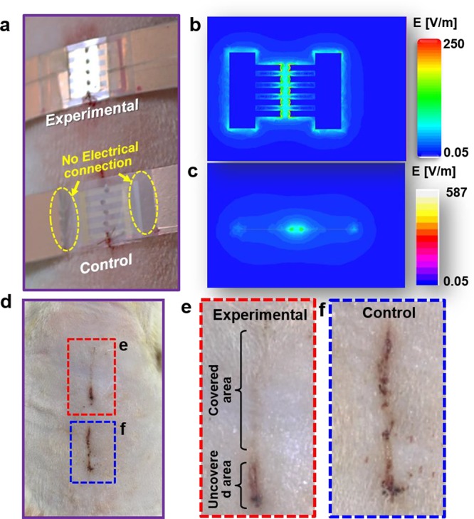
Wound healing under the stimulation of activated/inactivated electric field (EF). (a) Digital image of experimental group (with electrode connected to NG) and control group (no connection between electrode and NG) attached on the wound of rat. (b) Front and (c) lateral view of electric field distribution (simulated by COMSOL). (d) Digital image of wound recovery after 2 days in both experimental (dashed red rectangle) and control (dashed blue rectangle) groups. (e, f) Enlarged images of the wound areas from (d).
After the rats wore the devices for 2 days under normal activity, the wounds were examined and compared (Figure 2d). The electrode-covered region in the experimental groups showed a nearly complete recovery (Figure 2e). Small dots with slightly darker color could be observed from the wounded zone, corresponding to the electrode teeth distribution. Along the same wound, the uncovered area was still not fully healed. A similar unhealed wound surface was observed from all of the control wounds (with disconnected Au electrodes and blank control groups) in all rat models (Figure 2f and Figure S3b,d, three groups and n = 3 in each group). These observations suggest that the electric fields generated by the NG could facilitate the recovery of linear skin wounds on rats. Post experimental examination also revealed that the dressing electrodes remained intact after 3 days of operation, confirming their excellent stability when attached to the skin surface (Figure S4).
To further understand the influence of an electric field, interdigitated dressing electrodes were implemented for wound healing (Figure S5). In this setup, the linear wound was aligned perpendicular to the electrode pairs; therefore, the electric field was parallel to the wound direction. While the strength of electric field was comparable to the original test, no obvious difference was observed in wound healing by comparing the experimental and control groups, indicating that the electric field direction was an important factor for wound healing.
Nevertheless, linear acute skin wounds often heal fairly fast, and their closure rate cannot be reliably quantified. Therefore, the self-stimulated wound healing was further explored on full-thickness rectangular skin wounds using a pair of parallel line electrodes. First, the electric filed strength influences were investigated by using a parallel set of electrode pairs with their electrode gaps varied from 0.8 to 2.2 cm on full thickness square wounds (around 0.4 cm × 0.4 cm) (Figure S6). In general, a higher healing rate was obtained from higher electric field strength. To ensure a reasonable healing rate and moderate applied electric field strength, ∼ 250 V/m electric field strength was used in the following quantitative wound-healing studies.
As shown in Figure 3a-i, the proximal wound (top of image) was aligned in between the two vertical line electrodes and the electric field was along the horizontal direction. The distal wound (bottom of image) was covered by the same electrode setup but without an electric field as a control. After 3 days, the wound exposed to an electric field exhibited improved wound closure (Figure 3a-ii). Conversely, the control wound was still open with nonorderly wound healing consistent with contraction. This phenomenon further confirmed that the small discrete electric field generated by NG was able to direct and facilitate the wound recovery along the direction of the electric field. Without the electric field, large-area wounds show a radial healing direction due to contraction with a much slower rate, which was driven by the endogenous electric field (Figure S7). To further analyze the microscopic wound-healing characteristics of the electric field, after 2 days of treatment, the tissues were harvested, sectioned, and stained with hematoxylin and eosin (Figure 3b). The treated skin exhibited a completely healed wound with normal appearing epithelialization, while the control skin exhibited granulation tissue at the site of the wound, lacking epithelialization over the wounded area.
Figure 3.
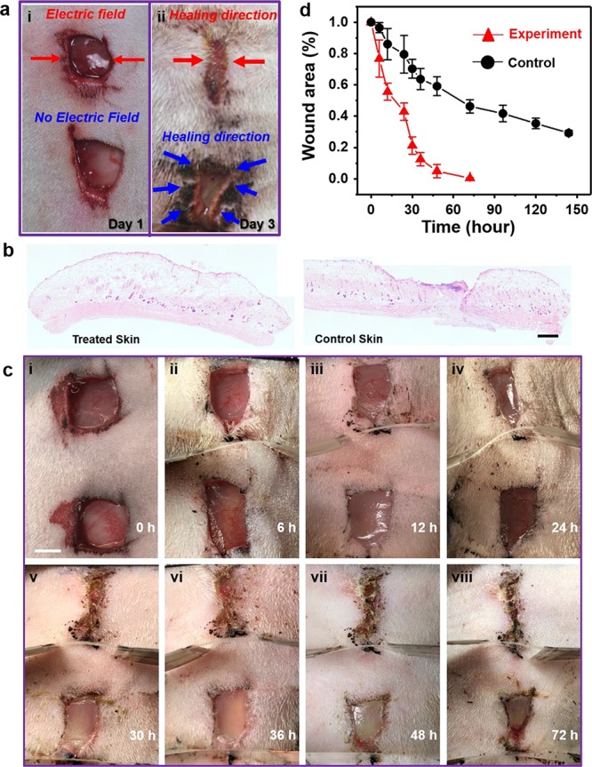
Scaled wound healing and healing efficiency comparison. (a) Digital image of a 3-day healing process for rectangular wounds with (experimental group) and without (control group) electric field. (b) Representative example of H&E stained sections of the center of a wound after 2 days of treatment with or without NG. Scale bar is 2.5 mm. (c) Digital images of time-varying (0−72 h) healing process for square wounds with (experimental group) and without (control group) electrical field. Scale bar is 5 mm. (d) Wound area as a function of time with (red curve) and without (black curve) electric field stimulation (n = 3).
Following the accelerated wound healing observed on rat’s skin, rectangular wounds were then used to quantify the wound closure rate driven by the discrete NG electric field. The series of images taken during the healing process (Figure 3c) clearly demonstrates that under a discrete parallel electric field the experimental wound (upper wound in each image) healed much faster than the control wound (lower wound in each image). The wound was completely closed along the electric field direction within 72 h; meanwhile, the control wound still had 46% wound area remaining open. It took ∼10–12 days for the control wounds and the untouched wounds (Figure S7) to recover to the same level, which was comparable to other reported wound-healing behavior in loose-skinned animals, such as mouse, rat, and rabbit.9 It should be noted that loose skinned animals heal their wounds mostly by contraction in contrast to humans whose wounds heal mostly by re-epithelialization.33 Recognizing this difference, future more clinical-relevant studies will need to shift to swine and human skin models.
From the series of images, the NG-facilitated wound recovery behavior was quantified (i.e., change in normalized wound area as a function of time). As shown in Figure 3d, in the presence of NG electric fields, the wound area (red triangles) reduced rapidly and reached a nearly complete closure (94% ± 4.3%, three groups and n = 3 in each group) within the first 48 h (the healing process is shown in Figure S8). Without the electric field, the wounds exhibited a normal wound contraction behavior, where the wound area slowly reduced to 30% within the first 150 h (black dots). The rate of healing declined as the wounds reached full closure. The NG-accelerated wound-healing behavior was then compared to other reported representative treatment strategies. Other representative wound treatment strategies, such as stem cell therapy (Vehicle-M, FB-M, and MSC-M),34,35 nanomaterial dressing therapy (ZnO, CS, CS-ZnO-0.5, and CS-Ag/ZnO-0.5),36 and laser therapy (4 and 8 J/cm2),37 all exhibited a closure time of more than 7 days for similar wounds on rat skins (a detailed comparison is included in Figure S9). It can be seen that our strategy provided a very short wound closure time (3 days), supporting the excellent wound-healing behavior enabled by the discrete NG electric fields.
To understand the mechanism of the accelerated wound-healing behavior, fibroblast cell growth under the same electrical stimulation was studied in vitro. It is known that fibroblasts play a vital role in the highly coordinated biological process of dermal wound healing.38,39 In the early stage of wound healing, fibroblasts migrate to the wound area, proliferate, and interact with surrounding cells (keratinocytes, fat cells and mast cells). Afterward, fibroblasts differentiate and produce extracellular matrix (ECM), glycoproteins, adhesive molecules and various cytokines. The generated collagen-based ECM then replaces the provisional fibrin-based matrix and helps reapproximate wound edges through their contractile properties.
First, the proliferation of fibroblast cells was studied by comparing the cell viability cultured with and without the NG electric filed. As schematically shown in Figure 4a, fibroblast cells were in a 96-well plate. A NG electric field (4 V/cm, Figure S10) was applied to the seventh column via a pair of line electrodes (as marked by the gold dashed lines). After 72 h of culture, cell viability in different columns was measured by the MTT assay. The first, second, and twelfth columns were used as controls since they were the farthest from the electric field, and their viability was considered as 100%. The viability of the third, fifth, seventh, ninth, and eleventh column was measured and shown in the plot. Column 7 (the electrical dressing group) showed the highest cell viability of 127% ± 14.37%, and columns 5 and 9 showed lower values of 112% ± 18.73% and 113% ± 16.43%, respectively (n = 8). The distributed >100% viability revealed a possible correlation between the strength of electric field and the cell viability.
Figure 4.

Influence of electric field on cells. (a) Schematic image of cells cultured in 96-well plate with stimulation from NG and cell viability of different columns in a 96-well plate (n = 8). (b) Schematic image of cells cultured in a dish with Au electrodes connected and disconnected to NG generated pulse voltage. Middle inset is the simulated electric filed distribution in the culture dish when the electrodes are connected to a NG with ±2 V out voltage. (c) Cultured cell morphology at different time points without (control) and with (experimental) electrical stimulation. Obvious proliferation and differentiation of cells at later time points were observed. (d) Western blot analysis and comparison of TGF-β, EGF, and VEGF growth factors (n= 3) with and without NG stimulation. (e) ROS results of blank control (BC), AC (alternating electric field generated by function generator), and NG (n = 5, p < 0.01).
Furthermore, the migration and assembly of fibroblast cells was investigated in a single culturing dish under the influence of the NG electric field. As schematically shown in Figure 4b, a pair of Au electrodes (0.5 cm spaced) were placed against the dish wall in parallel. After cells adhered to the dish, electrodes of experimental group were connected to the NG to produce a 2 V/cm electric field within the dish at a frequency of 1 Hz. Microscopic photographs were taken every 2 h and are shown in Figure 4c (the control group and the experimental group). The fibroblasts in the control group exhibited little noticeable change within the first 12 h (Figure 4c-i to 4c-iv). However, the one with an NG electric field started to show linear alignment within 2 h (Figure 4c-i′). After 4 h, fibroblasts exhibited a rapid proliferation and aligned well into multiple parallel lines (Figure 4c-ii′). As the electric field stimulation proceeded for more than 6 h, fibroblasts continued to proliferate and differentiate along the lines of the electric field (Figure 4c-iii′ and -iv′). This observation suggested that the electric field may facilitate the fibroblasts differentiating into myofibroblasts, thus providing a contraction force for wound closure.
Western blot analysis was further used to investigate the potential influences of the NG electric field to three typical growth factors involved in wound healing, including transforming growth factor beta (TGF-β),40 epidermal growth factor (EGF),41 and vascular endothelial growth factor (VEGF). As shown in Figure 4d, TGF-β, EGF, and VEGF all showed an enhanced expression in NG-stimulated tissues as compared to the control groups. In particular, the EGF expression exhibited a statistically significant enhancement (P = 0.0085), which is related to increasing proliferation and phenotypic expression of keratinocytes.41 This analysis suggested that the improved cell proliferation could be a result of the raised level of growth factors stimulated by NG electric field.
It is noteworthy to point out that for electric fields, typically high-amplitude and/or high frequency electrical pulses have been used and studied as a wound recovery strategy, whereas the effect was not ideal because intensive exposure to electric fields might induce certain side effects.42−44 To distinguish the effect from the discrete NG electric field from traditional alternating current (AC) electrical stimulation, we tested the total reactive oxygen species (ROS) amount generated with high glucose modified Eagle medium (DMEM) that was stimulated by an NG (Figure S11a) or a function generator (Figure S11b), along with a blank control. The peak-to-peak voltage generated by NG (Figure S11c) and the function generator (Figure S11d) were nearly the same, which means the electric field applied to the testing area was the same. As summarized in Figure 4e, the NG groups exhibited a higher ROS level (by 65%) as compared to the blank control groups (BC), whereas the function generator group (AC) showed a dramatically increased ROS level that was 489 ± 29% and 424 ± 23% (n = 5) higher than that of BC and NG groups, respectively. The significantly higher ROS level induced by normal AC signal would be harmful to the biological system or even cause cell death.45 The advantageous results from the NG pulses could be attributed to the natural mechanism of its voltage generation mechanism, which is determined by the limited number of surface charges rather than infinite amount of charge provided by the signal generator to maintain design voltage profile.
Conclusion
In summary, we demonstrated a highly efficient wound recovery strategy based on a wearable NG device. The device can locally convert the kinetic energy generated from a rat breathing into a discrete AC voltage signal and apply the electric field directly on the wound to enhance skin regeneration. Animal studies demonstrated a rapid closure of full-thickness rectangular skin wound within 3 days as compared to 12 days of normal healing process. In vitro data showed that the therapeutic effects were attributed to the electric field which promotes fibroblast migration, proliferation, and transdifferentiation. Moreover, the NG-based bandage produced a safe and very low-level electricity over the wounds, which is favorable for lowering the level of discomfort or pain. This self-stimulated electrotherapy for wound healing could have an impact on other related diseases (e.g., Raynaud’s disease) and may resolve cosmetic concerns, such as chickenpox scars, acne, keloid scarring, or rosacea. Better understanding and optimization of this physical treatment strategy will impact multidisciplinary research directions including surgical, biochemical, and translational sciences and eventually bring an effective therapeutic strategy to chronic disease treatment.
Experimental Section
Fabrication and Characterization of NG-Based Self-Activated Bandage
A PET (CS Hyde Co.) film (22 cm × 1.2 cm × 75 μm) film was used as the substrate, and two pieces of Cu foil (10 cm× 1.2 cm × 25 μm) were attached to both sides of PET substrate as the NG electrodes. A PTEF (CS Hyde Co.) film (10 cm × 1.2 cm× 25 μm) was attached to the top of one Cu electrode as the triboelectric active layer. Working electrodes (Au 50 nm and Cr 10 nm) for electrical stimulation were deposited on the PET substrate by E-beam Evaporation (CHA-600). A dummy device for control experiment was fabricated using the same design and procedure, but only with the working electrodes disconnected from the NG electrodes. For performance characterization, the PET film was tied around the rat’s torso. The voltage outputs were recorded between the two working electrodes using an Agilent DSO1012A oscilloscope (1 MΩ internal resistance) when the rat was under anesthesia, calm, and with normal activity. The bendability of PET film, PET film with Cu foil, and bandage was tested with a dynamic mechanical analyzer RSA III.
Wound Recovery Experiments
All animal experiments were conducted under a protocol approved by the University of Wisconsin Institutional Animal Care and Use Committee. Adult Sprague–Dawley (SD) rats (300g) were used for wound-healing experiments (all experiments were repeated using three groups of SD rats, n = 3 in each group). Anesthesia was first induced by inhalation of 2–5% isoflurane and maintained with 2% isoflurane. After anesthesia, rats were fixed in a prone position, and the dorsum was shaved and cleaned with alcohol. Two full thickness excisional linear (1 cm) or rectangular wounds (0.8 cm × 0.8 cm) were created along the shaved back of each rat. The self-activated bandage was wrapped around the rat, and the wound areas were covered with working electrodes. The control experiments were set on the adjacent area with the same type of wounds covered by the dummy device or blank substrates. Bioglue (CryoLife, Inc.) was used to adhere the bandages to the rats’ skin 0.5–1 cm away from the wound. A cotton net (3 M Health Care, St. Paul, MN) was used to fix the device. Wound healing was quantified by measuring remaining wound area using ImageJ. Wounds were considered completely closed if moist granulation tissue was no longer apparent and the wounded area was covered with epithelium.
After the final tracing, rats were euthanized and the entire wound area, including ∼5 mm of the adjacent normal skin, was excised down to the fascia and removed. The wound was divided in half and placed in Bouin’s fixative overnight. The wounds were then bisected down the center for routine hematoxylin and eosin (H&E) staining. Representative sections from treatment and control tissues were imaged using a Nikon Ti–S inverted microscope and digital images were captured with Nikon DS Ri2 cooled color camera, X-Cite 120LED BOOST System lamp from Excelitas, and Nikon Imaging Software, NIS Elements (Nikon, Tokyo, Japan). Bright field images of H&E were taken at 40× magnification.
MTT Assay
NIH 3T3 fibroblasts (HUVECs, CAMBREX) were cultured in a complete growth media that comprised high glucose modified Eagle medium (DMEM) with l-glutamine, supplemented with 15% fetal bovine serum (Hyclone; Thermo Fisher Scientific). The cells were seeded into 96-well culture plates, maintained at 37 °C in a humidified atmosphere in the presence of 5% CO2, and the culture medium was changed every day. The seventh column of the 96-well culture plate was applied a voltage generated by NG, and the first, second, and twelfth columns were used as controls. After 72 h, MTT (3-(4,5-dimethylthiazol-2-thiazolyl)-2,5-diphenyl-2H-tetrazolium bromide) assay (ThermoFisher Scientific) was performed to examine cell viability. MTT solution (100 μL) was added to each well. After 4 h of incubation, the medium was removed, and DMSO (500 μL/well) was added to dissolve the precipitated fomazan. The optical density (n = 3) of the solution was evaluated using a microplate spectrophotometer at a wavelength of 490 nm.
Cell Morphology under Electric Field
NIH 3T3 cells were cultured in 30 × 10 mm cell culture dishes (Thermo Fisher Scientific) with activated (experimental) and inactivated (control) Au electrodes (1 cm × 0.1 cm) placed against the dish wall. For cell culture under electric stimulation from NG, the Au electrodes were connected to contact-separate NG which was driven by a linear motor controlled through computer at a frequency of 1 Hz. For cell culture under electric stimulation from function generator, the Au electrodes were connected to function generator which output voltage with the same amplitude and frequency as NG. For control group, no electric stimulation was applied for cell culture. Cell morphology was observed periodically using an inverted optical microscope (Nikon Eclipse Ti–U, Japan).
Reactive Oxygen Species Analysis
Three 30 × 10 mm cell culture dishes with Au electrodes (1 cm × 0.1 cm) placed against the dish wall were utilized. A 2.5 mL portion of high glucose modified Eagle medium (DMEM) with l-glutamine with 10% fetal bovine serum (Hyclone; Thermo Fisher Scientific) was add to each dish. For the ROS test under electric stimulation from NG, the Au electrodes were connected to contact-separate NG which was driven by a linear motor controlled through computer at a frequency of 1 Hz. For ROS under electric stimulation from function generator, the Au electrodes were connected to function generator which output voltage with same amplitude and same frequency as NG. For the control group, no electric stimulation was applied. ROS concentrations were measured using 2′,7′-dichlorodihydrofluorescein diacetate (H2DCFDA) (Molecular Probes). A 0.2 mL portion of solution was taken out from each dish every 30 min and was mixed with 2 μL of H2DCFDA (5 mg/mL) DMSO solution. The mixture was incubated for 30 min at 37 °C. The fluorescence intensity (Excitation:504 nm/Emission: 529 nm) was measured in a microplate reader (ClarioStar Plate Reader).
Western Blot Analysis
Skin tissues were harvested from the mice of nanogenerator-treated or control group at day 2. The tissue samples were homogenized in RIPA buffer (Boston BioProducts) added with proteinase inhibitor (Thermo Scientific) by using a Dounce homogenizer on the ice for 10–15 min. Then the supernatants were obtained by centrifugation at 20000g for 20 min and measured by a nanodrop reader (Thermo Scientific). Western blot analysis was performed by using 4–12% sodium dodecyl sulfate–polyacrylamide gel (Invitrogen) and iBlot 2 Dry Blotting System (Invitrogen). The PVDF membrane carrying the samples were probed by using the antibodies against VEGF (Thermo Scientific), EGF, TGF-β (R&D), and β-actin (Li-Cor) at 4 °C overnight and then detected by fluorescence-conjugated secondary antibodies (Li-Cor) for 1 h at room temperature. Finally, the blots were obtained via the Odyssey imaging system.
Acknowledgments
This publication was supported by the National Institute of Biomedical Imaging and Bioengineering of the National Institutes of Health under Award Nos. R01EB021336 and P30CA014520. The content is solely the responsibility of the authors and does not necessarily represent the official views of the National Institutes of Health.
Supporting Information Available
The Supporting Information is available free of charge on the ACS Publications website at DOI: 10.1021/acsnano.8b07038.
Schematic of electricity generated by bandage; voltage, current, and power output of the NG; healing of linear wounds treated with perpendicular alignment of electrode pairs; integrity of Au electrodes; small wound’s healing experiment under interdigitated electrodes; scaled wound’s healing under varied electric fields; naturally healed wounds; serial photographs of scaled wounds; comparison of wound closure as a function of time under the stimulations of different techniques; voltage outputs of contact-mode NG; ROS test experiment details; digital images of blood vessel proliferation in wound area (PDF)
Author Contributions
# Y.L. and H.W. contributed equally to this work.
Author Contributions
Y.L. and X.W. conceived the idea. Y.L., H.W., W.C., and X.W. designed the experiments. X.W., W.C., and A.G. oversaw the project progress. Y.L. and H.W. performed the main experiments and analyzed the data. J.L., G.Y., B.Y., and D.N. participated in device fabrication and electric field simulation. E.O. and A.G. conducted the histologic experiments. Y.L., X.W., W.C., and A.G wrote the manuscript. All authors reviewed and commented on the manuscript.
The authors declare no competing financial interest.
Supplementary Material
References
- Sen C. K.; Gordillo G. M.; Roy S.; Kirsner R.; Lambert L.; Hunt T. K.; Gottrup F.; Gurtner G. C.; Longaker M. T. Human Skin Wounds: A Major and Snowballing Threat to Public Health and the Economy. Wound Repair Regen 2009, 17, 763–771. 10.1111/j.1524-475X.2009.00543.x. [DOI] [PMC free article] [PubMed] [Google Scholar]
- Armstrong D. G.; Kanda V. A.; Lavery L. A.; Marston W.; Mills J. L.; Boulton A. J. Mind the Gap: Disparity between Research Funding and Costs of Care for Diabetic Foot Ulcers. Diabetes Care 2013, 36, 1815–1817. 10.2337/dc12-2285. [DOI] [PMC free article] [PubMed] [Google Scholar]
- Gottrup F.; Apelqvist J.; Price P. Outcomes in Controlled and Comparative Studies on Non-Healing Wounds: Recommendations to Improve the Quality of Evidence in Wound Management. J. Wound Care 2010, 19, 237–268. 10.12968/jowc.2010.19.6.48471. [DOI] [PubMed] [Google Scholar]
- Miao Q.; Yeo D. C.; Wiraja C.; Zhang J.; Ning X.; Xu C.; Pu K. Near-Infrared Fluorescent Molecular Probe for Sensitive Imaging of Keloid. Angew. Chem. 2018, 130, 1270–1274. 10.1002/ange.201710727. [DOI] [PubMed] [Google Scholar]
- Shah J. B. The History of Wound Care. J. Am. Coll Clin Wound Spec 2011, 3, 65–66. 10.1016/j.jcws.2012.04.002. [DOI] [PMC free article] [PubMed] [Google Scholar]
- Griffin D. R.; Weaver W. M.; Scumpia P. O.; Di Carlo D.; Segura T. Accelerated Wound Healing by Injectable Microporous Gel Scaffolds Assembled from Annealed Building Blocks. Nat. Mater. 2015, 14, 737. 10.1038/nmat4294. [DOI] [PMC free article] [PubMed] [Google Scholar]
- O’brien J.; Grace P.; Perry I.; Hannigan A.; Clarke Moloney M.; Burke P. Randomized Clinical Trial and Economic Analysis of Four-Layer Compression Bandaging for Venous Ulcers. Br. J. Surg. 2003, 90, 794–798. 10.1002/bjs.4167. [DOI] [PubMed] [Google Scholar]
- Jayakumar R.; Prabaharan M.; Kumar P. S.; Nair S.; Tamura H. Biomaterials Based on Chitin and Chitosan in Wound Dressing Applications. Biotechnol. Adv. 2011, 29, 322–337. 10.1016/j.biotechadv.2011.01.005. [DOI] [PubMed] [Google Scholar]
- Kamoun E. A.; Kenawy E.-R. S.; Chen X. A Review on Polymeric Hydrogel Membranes for Wound Dressing Applications: Pva-Based Hydrogel Dressings. J. Adv. Res. 2017, 8, 217–233. 10.1016/j.jare.2017.01.005. [DOI] [PMC free article] [PubMed] [Google Scholar]
- Kranke P.; Bennett M.; Roeckl-Wiedmann I.; Debus S. Hyperbaric Oxygen Therapy for Chronic Wounds. Cochrane Database Syst. Rev. 2004, 10.1002/14651858.CD004123.pub2. [DOI] [PubMed] [Google Scholar]
- Ubbink D.; Westerbos S.; Nelson E.; Vermeulen H. A Systematic Review of Topical Negative Pressure Therapy for Acute and Chronic Wounds. Br. J. Surg. 2008, 95, 685–692. 10.1002/bjs.6238. [DOI] [PubMed] [Google Scholar]
- Dyson M.; Moodley S.; Verjee L.; Verling W.; Weinman J.; Wilson P. Wound Healing Assessment Using 20 MHz Ultrasound and Photography. Skin Res. Technol. 2003, 9, 116–121. 10.1034/j.1600-0846.2003.00020.x. [DOI] [PubMed] [Google Scholar]
- Kloth L. C. Electrical Stimulation for Wound Healing: A Review of Evidence from in Vitro Studies, Animal Experiments, and Clinical Trials. Int. J. Lower Extremity Wounds 2005, 4, 23–44. 10.1177/1534734605275733. [DOI] [PubMed] [Google Scholar]
- Kloth L. C. Electrical Stimulation Technologies for Wound Healing. Adv. Wound Care 2014, 3, 81–90. 10.1089/wound.2013.0459. [DOI] [PMC free article] [PubMed] [Google Scholar]
- Barrientos S.; Stojadinovic O.; Golinko M. S.; Brem H.; Tomic-Canic M. Growth Factors and Cytokines in Wound Healing. Wound Repair Regen 2008, 16, 585–601. 10.1111/j.1524-475X.2008.00410.x. [DOI] [PubMed] [Google Scholar]
- Borena B. M.; Martens A.; Broeckx S. Y.; Meyer E.; Chiers K.; Duchateau L.; Spaas J. H. Regenerative Skin Wound Healing in Mammals: State-of-the-Art on Growth Factor and Stem Cell Based Treatments. Cell. Physiol. Biochem. 2015, 36, 1–23. 10.1159/000374049. [DOI] [PubMed] [Google Scholar]
- Vodovnik L.; Karba R. Treatment of Chronic Wounds by Means of Electric and Electromagnetic Fields Part 1 Literature Review. Med. Biol. Eng. Comput. 1992, 30, 257–266. 10.1007/BF02446963. [DOI] [PubMed] [Google Scholar]
- Wolcott L. E.; Wheeler P. C.; Hardwicke H. M.; Rowley B. A. Accelerated Healing of Skin Ulcer by Electrotherapy: Preliminary Clinical Results. South. Med. J. 1969, 62, 795–801. 10.1097/00007611-196907000-00008. [DOI] [PubMed] [Google Scholar]
- Thakral G.; LaFontaine J.; Najafi B.; Talal T. K.; Kim P.; Lavery L. A. Electrical Stimulation to Accelerate Wound Healing. Diabet Foot Ankle 2013, 4, 22081. 10.3402/dfa.v4i0.22081. [DOI] [PMC free article] [PubMed] [Google Scholar]
- Song B.; Gu Y.; Pu J.; Reid B.; Zhao Z.; Zhao M. Application of Direct Current Electric Fields to Cells and Tissues in Vitro and Modulation of Wound Electric Field in Vivo. Nat. Protoc. 2007, 2, 1479. 10.1038/nprot.2007.205. [DOI] [PubMed] [Google Scholar]
- Gentzkow G. D. Electrical Stimulation to Heal Dermal Wounds. J. Dermatol. Surg. Oncol. 1993, 19, 753–758. 10.1111/j.1524-4725.1993.tb00420.x. [DOI] [PubMed] [Google Scholar]
- Seung W.; Gupta M. K.; Lee K. Y.; Shin K.-S.; Lee J.-H.; Kim T. Y.; Kim S.; Lin J.; Kim J. H.; Kim S.-W. Nanopatterned Textile-Based Wearable Triboelectric Nanogenerator. ACS Nano 2015, 9, 3501–3509. 10.1021/nn507221f. [DOI] [PubMed] [Google Scholar]
- Zhao Z.; Yan C.; Liu Z.; Fu X.; Peng L. M.; Hu Y.; Zheng Z. Machine-Washable Textile Triboelectric Nanogenerators for Effective Human Respiratory Monitoring through Loom Weaving of Metallic Yarns. Adv. Mater. 2016, 28, 10267–10274. 10.1002/adma.201603679. [DOI] [PubMed] [Google Scholar]
- Pu X.; Guo H.; Chen J.; Wang X.; Xi Y.; Hu C.; Wang Z. L. Eye Motion Triggered Self-Powered Mechnosensational Communication System Using Triboelectric Nanogenerator. Sci. Adv. 2017, 3, e1700694 10.1126/sciadv.1700694. [DOI] [PMC free article] [PubMed] [Google Scholar]
- Chen X.; Song Y.; Chen H.; Zhang J.; Zhang H. An Ultrathin Stretchable Triboelectric Nanogenerator with Coplanar Electrode for Energy Harvesting and Gesture Sensing. J. Mater. Chem. A 2017, 5, 12361–12368. 10.1039/C7TA03092D. [DOI] [Google Scholar]
- Bandodkar A. J.; You J.-M.; Kim N.-H.; Gu Y.; Kumar R.; Mohan A. V.; Kurniawan J.; Imani S.; Nakagawa T.; Parish B. Soft, Stretchable, High Power Density Electronic Skin-Based Biofuel Cells for Scavenging Energy from Human Sweat. Energy Environ. Sci. 2017, 10, 1581–1589. 10.1039/C7EE00865A. [DOI] [Google Scholar]
- Xu S.; Zhang Y.; Jia L.; Mathewson K. E.; Jang K.-I.; Kim J.; Fu H.; Huang X.; Chava P.; Wang R. Soft Microfluidic Assemblies of Sensors, Circuits, and Radios for the Skin. Science 2014, 344, 70–74. 10.1126/science.1250169. [DOI] [PubMed] [Google Scholar]
- Palsaniya S.; Nemade H. B.; Dasmahapatra A. K. In Size Dependent Triboelectric Nanogenerator and Effect of Temperature, Microwave and Photonics (ICMAP), 2018 3rd International Conference on; IEEE, 2018; pp 1–2.
- Nguyen V.; Yang R. Effect of Humidity and Pressure on the Triboelectric Nanogenerator. Nano Energy 2013, 2, 604–608. 10.1016/j.nanoen.2013.07.012. [DOI] [Google Scholar]
- Lee K. Y.; Chun J.; Lee J. H.; Kim K. N.; Kang N. R.; Kim J. Y.; Kim M. H.; Shin K. S.; Gupta M. K.; Baik J. M. Hydrophobic Sponge Structure-Based Triboelectric Nanogenerator. Adv. Mater. 2014, 26, 5037–5042. 10.1002/adma.201401184. [DOI] [PubMed] [Google Scholar]
- Lyu Y.; Zeng J.; Jiang Y.; Zhen X.; Wang T.; Qiu S.; Lou X.; Gao M.; Pu K. Enhancing Both Biodegradability and Efficacy of Semiconducting Polymer Nanoparticles for Photoacoustic Imaging and Photothermal Therapy. ACS Nano 2018, 12, 1801–1810. 10.1021/acsnano.7b08616. [DOI] [PubMed] [Google Scholar]
- Nuccitelli R. A Role for Endogenous Electric Fields in Wound Healing. Curr. Top. Dev. Biol. 2003, 58, 1–26. 10.1016/S0070-2153(03)58001-2. [DOI] [PubMed] [Google Scholar]
- Ansell D. M.; Holden K. A.; Hardman M. J. Animal Models of Wound Repair: Are They Cutting It?. Exp. Dermatol. 2012, 21, 581. 10.1111/j.1600-0625.2012.01540.x. [DOI] [PubMed] [Google Scholar]
- Chen L.; Tredget E. E.; Wu P. Y.; Wu Y. Paracrine Factors of Mesenchymal Stem Cells Recruit Macrophages and Endothelial Lineage Cells and Enhance Wound Healing. PLoS One 2008, 3, e1886 10.1371/journal.pone.0001886. [DOI] [PMC free article] [PubMed] [Google Scholar]
- Kou X.; Xu X.; Chen C.; Sanmillan M. L.; Cai T.; Zhou Y.; Giraudo C.; Le A.; Shi S. The Fas/Fap-1/Cav-1 Complex Regulates Il-1ra Secretion in Mesenchymal Stem Cells to Accelerate Wound Healing. Sci. Transl. Med. 2018, 10, eaai8524. 10.1126/scitranslmed.aai8524. [DOI] [PMC free article] [PubMed] [Google Scholar]
- Lu Z.; Gao J.; He Q.; Wu J.; Liang D.; Yang H.; Chen R. Enhanced Antibacterial and Wound Healing Activities of Microporous Chitosan-Ag/Zno Composite Dressing. Carbohydr. Polym. 2017, 156, 460–469. 10.1016/j.carbpol.2016.09.051. [DOI] [PubMed] [Google Scholar]
- Medrado A. R.; Pugliese L. S.; Reis S. R. A.; Andrade Z. A. Influence of Low Level Laser Therapy on Wound Healing and Its Biological Action Upon Myofibroblasts. Lasers Surg. Med. 2003, 32, 239–244. 10.1002/lsm.10126. [DOI] [PubMed] [Google Scholar]
- Pillouer-Prost A. L. Fibroblasts: What’s New in Cellular Biology?. J. Cosmet. Laser Ther. 2003, 5, 232–238. 10.1080/14764170310021869. [DOI] [PubMed] [Google Scholar]
- Gosain A.; DiPietro L. A. Aging and Wound Healing. World J. Surg. 2004, 28, 321–326. 10.1007/s00268-003-7397-6. [DOI] [PubMed] [Google Scholar]
- Montesano R.; Orci L. Transforming Growth Factor Beta Stimulates Collagen-Matrix Contraction by Fibroblasts: Implications for Wound Healing. Proc. Natl. Acad. Sci. U. S. A. 1988, 85, 4894–4897. 10.1073/pnas.85.13.4894. [DOI] [PMC free article] [PubMed] [Google Scholar]
- Choi J. S.; Leong K. W.; Yoo H. S. In Vivo Wound Healing of Diabetic Ulcers Using Electrospun Nanofibers Immobilized with Human Epidermal Growth Factor (Egf). Biomaterials 2008, 29, 587–596. 10.1016/j.biomaterials.2007.10.012. [DOI] [PubMed] [Google Scholar]
- Guenel P.; Nicolau J.; Imbernon E.; Chevalier A.; Goldberg M. Exposure to 50-Hz Electric Field and Incidence of Leukemia, Brain Tumors, and Other Cancers among French Electric Utility Workers. Am. J. Epidemiol. 1996, 144, 1107–1121. 10.1093/oxfordjournals.aje.a008889. [DOI] [PubMed] [Google Scholar]
- Knave B.; Gamberale F.; Bergström S.; Birke E.; Iregren A.; Kolmodin-Hedman B.; Wennberg A. Long-Term Exposure to Electric Fields: A Cross-Sectional Epidemiologic Investigation of Occupationally Exposed Workers in High-Voltage Substations. Scand. J. Work, Environ. Health 1979, 5, 115–125. 10.5271/sjweh.2661. [DOI] [PubMed] [Google Scholar]
- London S. J.; Thomas D. C.; Bowman J. D.; Sobel E.; Cheng T.-C.; Peters J. M. Exposure to Residential Electric and Magnetic Fields and Risk of Childhood Leukemia. Am. J. Epidemiol. 1991, 134, 923–937. 10.1093/oxfordjournals.aje.a116176. [DOI] [PubMed] [Google Scholar]
- Le M. B.; Clement M.; Pervaiz S.; Brenner C. Reactive Oxygen Species and the Mitochondrial Signaling Pathway of Cell Death. Histol. Histopathol. 2005, 20, 205–219. [DOI] [PubMed] [Google Scholar]
Associated Data
This section collects any data citations, data availability statements, or supplementary materials included in this article.