Abstract
Unicondylar Knee Arthroplasty (UKA) is a minimally-invasive surgical procedure for treating isolated compartmental knee osteoarthritis. Accurate implant placement is crucial for a successful UKA procedure. Previous work has shown the improvement in UKA by using robotic systems. Here, we present the implant alignment accuracy of a hand-held robotic UKA system compared with a conventional manual UKA system for 12 cadaver specimens. Two surgeons carried out equal number of medial UKAs with robotic UKA on one knee and the manual UKA on the other knee. Preoperative and postoperative computed tomography (CT) scans were obtained for each cadaveric model. The final implant positions were identified in the postoperative CT scan. The implant orientations were compared with the planned implant positions to obtain femoral and tibial implant alignment errors. Our results show that the femoral flexion, varus, and rotation root mean square errors for the robotic and conventional approach were 1.23°, 2.81°, 1.62° and 7.52°, 6.25°, 5.0°, respectively. The tibial slope and varus errors for the robotic and conventional approaches were 2.41°, 2.96° and 4.06°, 1.8°, respectively. We did not find any statistical significant difference (p=0.05) in the performance of the two surgeons. We conclude that the hand-held robotic UKA system offers significant improvement in the final implant placement
Keywords: unicondylar knee arthroplasty, partial knee replacement, implant accuracy, cadaver study
Introduction
Unicondylar Knee Arthroplasty (UKA) is a bone-sparing surgical procedure for treating patients with isolated compartmental knee osteoarthritis by replacing the damaged parts of the knee with implants[1]. Studies have shown that UKA procedures are associated with lower perioperative morbidity and faster patient recovery[2,3]. Furthermore, clinical and kinematic trials have shown that successful UKA procedures lead to knee function returning closer to a normal knee[4].
Early UKAs were less successful because of poorly designed implants, improper patient screening, and lack of proper surgical techniques [5]–[7]. More recent studies have documented the improvement in the UKA outcomes due to improvements in the previously-mentioned areas [2], [8]–[10]. Accurate implant placement is one of the key factors for improved outcomes. However, the UKA procedure is a minimally invasive one and is technically demanding. Thus, achieving accurate implant positioning is difficult and has been shown to be a major reason for aseptic implant loosening, excessive polyethylene wear, and progressive osteoarthritis in the un-operated condyle [11]–[13].
Multiple studies have shown the improved accuracy of UKA procedures when using robotically navigated systems [8], [14]–[16]. Cobb et al. compared the Acrobat robotic system versus conventional approach for UKA and found that the robotic system gave final tibiafemoral alignment within 2 degrees of the planned positions while the conventional approach obtained this accuracy in only 40% of the cases [8]. In another study, Citak et al. also demonstrated the improved accuracy of a robotic navigation system with dynamic bone tracking over the conventional approach [14]. However, both these studies involve use of a robotic arm for guiding the bone cuts. A hand-held robotic system has lower costs, a smaller footprint in the operating room and allows better ergonomics for the surgeon [17]. In this work, we compare the accuracy of a hand-held robotic navigation system with the conventional approach in cadaveric tests.
Materials and Methods
Data:
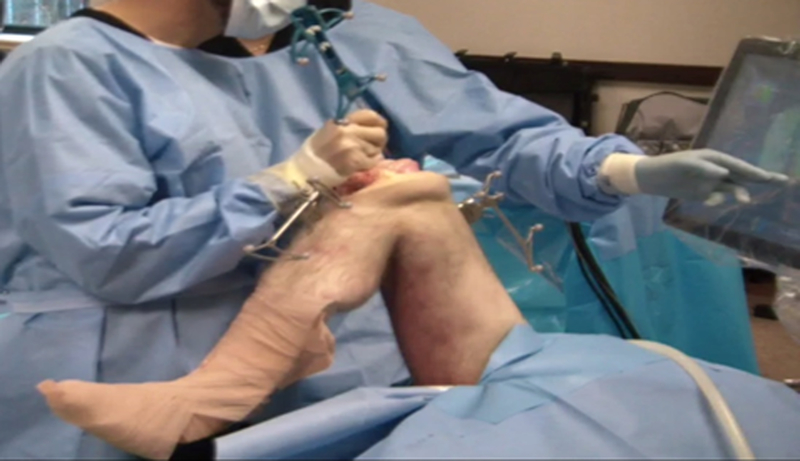
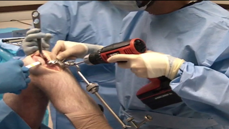
Twelve hip-to-toe cadaveric specimens were used in this study. The specimens were thawed two days prior to the UKA procedure. During the UKA procedure, the specimen was placed in a supine position on the operating table as shown in Fig. 1 and 2. Two surgeons carried out the UKA procedures for six specimens each. For each specimen, robotic navigated UKA (Navio, Smith & Nephew) was carried on one knee and the conventional approach was used for the other knee [17]. All the procedures were carried out on the medial side of the knee. Each surgeon carried out robotic UKAs on three left and three right knees. Preoperative computed tomography (CT) scans with 1.25–2.5 mm slice thickness were obtained for the cadaveric specimens. These CT scans were then reconstructed with 1mm z-resolution and used to determine the size of the UKA implants (Stride, Smith & Nephew). Conical divots were prepared in known positions on the manufactured implants in order to facilitate implant accuracy measurements in the intraoperative space. After the UKA procedures, postoperative CT scans were obtained for the cadaver specimens.
Figure 1.

Setup during a robotically navigated UKA procedure.
Figure 2.

Setup during conventional UKA procedure.
Robotic navigated approach:
During the robotic procedure, the surgeon first inserted bone screws into the femur and tibia and attached passive optical markers. In order to establish the anatomic reference frames of the femur and tibia, respective sets of anatomic landmarks were collected first. The hip center was calculated by pivoting the femur about the hip joint. Other bony landmarks such as the femoral and tibial knee center, epicondyles, and malleoli were directly collected with an optically tracked pointer. The pointer was also used to map out the articular surfaces of the femoral medial condyle and the tibial plateau. The robotic system was then used to intraoperatively plan the placement of the implants to replicate the original undamaged articular surfaces. Then, an optically tracked and robotically controlled hand-held drill was used to cut the bone according to the intraoperative plan. The divoted implant was then impacted into place and the divot locations on the implant were collected with a ball-tip probe. The implants were removed and cemented into place. Once again the implant divot positions were collected. During the procedure, multiple screws with divoted heads were also drilled into the femur and tibia and their divot positions were collected. These divot positions were later used to obtain a transformation from the intraoperative space to the postoperative CT space.
Conventional approach:
For the conventional procedure, the operation proceeded in five stages: 1) tibial cuts; 2) femoral distal cuts; 3) femoral finishing cuts; 4) femur contouring; and 5) tibial preparation. During the tibial cuts, an external tibial alignment rod (Fig. 2) was positioned and then the tibial cut jig, designed to obtain a 5 degrees tibial slope, was attached. Then, the tibial cut jig was stabilized using headless pins and transverse and sagittal cuts were made using an oscillating saw. Then, the tibial rod assembly was removed and a tibial spacer was used to measure the gap between the femoral condyle and the tibial cut surface under 90 degree flexion as well as extension. The tibial cut was then confirmed using an alignment T bar assembled on top of the tibial spacer. The looseness of the gaps under flexion and extension was then used to choose an appropriate femoral distal cut jig. The femoral distal cut jig was then attached and an oscillating saw was used to carry out the cut under full extension. Once the cuts were done the distal femoral jig was removed and the remaining distal cut was completed manually. Then, the femoral finishing guide of the appropriate size was attached to the femoral condyle. Subsequently, the posterior cut, femur implant post holes, and the anterior and chamfer cuts were carried out in the proper order. During femur contouring, appropriate tools were used to round out the sharp edges left by the saw cuts. Finally, during tibial prep, the appropriately sized tibial trial sizer was attached on top of the tibial cut made initially. This attachment was used to punch the keel for the tibial implant. The tibial trial sizer was then removed and the implants were impacted into place for trialling. Finally, the implants were cemented into place.
Alignment accuracy metrics:
In case of robotically navigated UKAs, we considered the planned implant positions in the intraoperative space as the gold standard. The final cemented implant positions that were also collected in the same intraoperative space were compared against the planned implant positions to obtain the implant flexion/extension, varus/valgus, and internal/external rotation orientation errors. To standardize the measurement technique for both the approaches, we carried out another set of measurements for the robotically navigated procedures. Here, the landmarks obtained in the intraoperative space were first transformed to the postoperative CT space by using a transformation between divoted screw positions captured in the intraoperative and the CT space. Then, the final implant positions were identified in the postoperative CT space. The difference in the two measurements was noted down. In case of the conventional approach, the procedure protocol and instrument design dictated the gold standard for the implant orientations. For conventional approach, the ideal implant positions were planned and positioned in the preoperative CT space. Validated custom software was used to also position surface models of the implants in the postoperative CT space. ITK-Snap software was then used to segment the femur and the tibia from the preoperative and the postoperative CT scan [18]. A rigid surface-to-surface registration algorithm was then used to obtain a transformation from the postoperative to the preoperative CT space for both the femur and the tibia. This transformation was then used to transform the final implant position to the preoperative CT space. The final and planned implant positons were compared in the preoperative CT space to obtain the final implant alignment errors. This approach is similar to that used by Dunbar et al. which was found to give RMS error of 0.9°and 1.7° in all directions for the femoral and tibial components, respectively[19].
Statistical analysis:
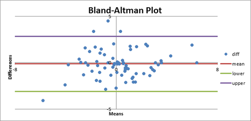
In our study, we used two different approaches for measuring the implant alignment error when using the robotic navigation system. To compare the performance of the two surgeons, we carried out a two-tailed Mann-Whitney test for the implant alignment errors for the cases carried out by the two surgeons. We found that there was no significant difference (p=0.05) in the alignment errors for the conventional or the robotically navigated procedures by the two surgeons. We carried out a Bland- Altman analysis to compare the two measurement metrics used for the robotically navigated data (Fig. 3) and found that the two methods gave similar measurement results. The root mean square (RMS) error, average and standard deviation for the alignment errors for femur and tibia were tabulated to compare the conventional and the robotically navigated approach.
Figure 3.

Bland-Altman plot comparing the two measurement metrics for estimating the alignment error during robotically navigated UKA.
Results
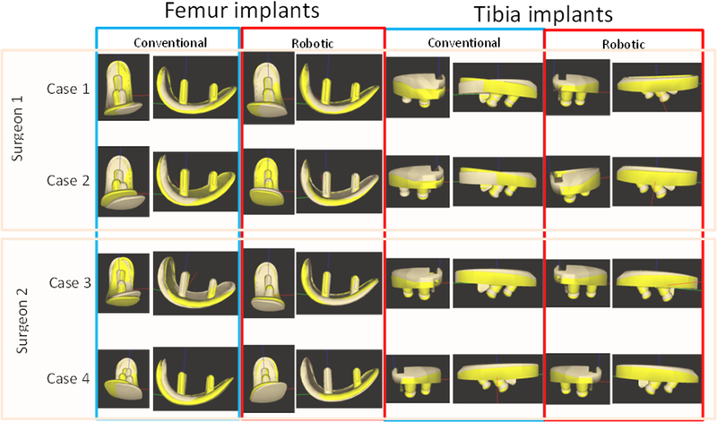
The results of our study are presented in Table 1 and graphically presented in Fig. 4. The maximum RMS femoral implant orientation error was less than 2.81° for the robotically navigated approach and less than 7.52° for the conventional approach. The maximum RMS tibial implant orientation error was less than 2.96° for the robotically navigated approach and less than 4.06° for the conventional approach. We note that the overall statistics obtained with the optical metrics are very similar to those from the CT metrics. We also see that the robotically navigated approach achieves low implant alignment errors for all the three orientation angles. The conventional approach achieves an RMS of 1.8 for the tibial varus alignment errors. However, all other alignment errors are higher than those obtained for robotically navigated procedures.
Table 1.
Orientation alignment errors for conventional approach and robotic navigated approach.
| Robotic navigated* (optical metric) |
Robotic navigated (CT metrics) |
Conventional | |||||||
|---|---|---|---|---|---|---|---|---|---|
| Mean±SD | Range | RMSE | Mean±SD | Range | RMSE | Mean±SD | Range | RMSE | |
| Femoral implant | |||||||||
| Flexion (°) | 0.48±1.19 | −0.77,3.66 | 1.23 | 0.68±1.51 | −3.4,1.83 | 1.60 | 0.27±7.85 | −11.69,15.09 | 7.52 |
| Varus (°) | 1.30±2.61 | −1.66,6.96 | 2.81 | 0.27±2.72 | −5.02,3.51 | 2.61 | −1.64±6.30 | −11.32,9.10 | 6.25 |
| Internal rotation (°) | −0.15±1.69 | −3.24,2.48 | 1.62 | 0.38±1.90 | −3.0,3.08 | 1.86 | −2.28±4.65 | −9.53,7.36 | 5.0 |
| Tibial implant | |||||||||
| Tibial slope (°) | 0.04±2.52 | −2.79,4.69 | 2.41 | −0.21±2.68 | −3.92,6.38 | 2.58 | 2.37±3.44 | −4.19,8.75 | 4.06 |
| Varus (°) | −0.13±3.10 | −7.82,3.23 | 2.96 | 0.08±2.31 | −3.42,3.78 | 2.22 | 0.29±1.88 | −3.24,2.92 | 1.8 |
for 11 cases
Figure 4.

Overlay of planned (light brown) and final (yellow) femoral and tibial implants for four cases for measured alignment components.
Discussion
UKA procedures facilitate faster patient recovery time due to smaller incisions and lesser bone removal [1]. Inaccurate implant alignment leads to UKA failures arising from aseptic loosening, excessive polyethylene wear, and progressive osteoarthritis in the un-operated condyle [11]–[13]. Use of robotic navigation systems with optically and mechanically tracked tools facilitate superior accuracy in implant alignment [8], [14]–[16].
Cobb et al. compared a hands-on robotic assistant, the Acrobot System (The Acrobot Co. Ltd., London, UK) with a conventional approach for 28 knees [8]. In this study, the authors found the Acrobot system gave the average absolute alignment errors as presented in Table 2. The Acrobot system uses a tactile robot and a static referencing system with rigid fixation of the tibia and the femur in an intraoperative stereotactic frame. Dunbar et al. used a different tactile robotic system (MAKO Surgical Corp, Fort Lauderdale, Fla) with a dynamic referencing system for 20 knees and compared the results with those obtained by using a static referencing frame [19]. The authors found the implant alignment errors to be comparable for dynamic and static referencing systems. Citak et al. used the same tactile robotic system with dynamic referencing and compared its implant alignment accuracy against a conventional system [14]. They found that the robotic system gave the RMS alignment errors as presented in Table 2. The robotic system that we have described here also uses a dynamic referencing system. In this system, an optically tracked hand-held drill is used to carry out the final cuts. This simplicity in design philosophy facilitates lower costs, leads to a smaller footprint and allows more ease of use for the surgeon. Furthermore, the results that we obtained from our studies reveals that the robotic system compares very favorably against the previously mentioned systems with the RMS alignment errors as shown in Table 2.
Table 2.
Comparison of RMS and average implant placement errors for three different robotic approaches.
| Direction | Hand-held robot |
Citak et al. |
Cobb et al. |
||
|---|---|---|---|---|---|
| Femur | Tibia | Femur | Tibia | Average | |
| Flexion | 1.23° | 2.41° | 2.9° | 0.9° | 1.5° |
| Varus | 2.81° | 2.96° | 2.0° | −4.9° | 1.3° |
| Rotation | 1.62° | * | −1.1° | 0.7° | 2.8° |
Our study suffers from the following limitations. The sample size for this study was very small and two surgeons carried out all the UKA procedures. The experience level of the two surgeons for both the conventional and the robotic system was different. However, our analysis shows that there is no significant difference in the results obtained for the two surgeons. The use of the robotic system also led to increased setup time and total procedure time. Furthermore, unlike previous studies, we did not compare the translation alignment errors and the tibial internal/external rotation error. This was because the ideal values for these positions were not known in case of the conventional approach. Also, during one of the robotic cases, the bone tracker on the femur moved and so we could not obtain reliable optical accuracy measurements for that case. This bone tracker movement happened during impacting of the implant onto the bone and so had no impact on the accuracy of the bone cut.
We see from the results for the RMS alignment error for the conventional approach that the tibial varus/valgus alignment error is very low. However, all the other alignment errors are relatively higher. This is because the conventional approach relied on the initial tibial cut to make all other subsequent cuts. The subsequent cuts involve errors caused due to instrument error, as well as estimations made while making the cuts. Thus, all other alignment errors are high. On the other hand, the robotic approach involved use of a steel bur to make the bone cuts. Thus, the alignment errors are uniformly spread across all the component values. We also note that the overall alignment error for both cases includes errors arising from the bone cuts as well as cementing. Thus, all the alignment errors presented here represent the upper limit for the actual implant alignment error for the approach.
In conclusion, the use of a robotic hand-held navigation system provides improved final implant orientation accuracy over conventional manual approach. However, further clinical studies are needed to evaluate the mid and long-term outcomes of the use of robotic navigation systems.
Footnotes
Disclosure of interest: Rahul Khare and Branislav Jaramaz are paid employees of Smith & Nephew Inc. Brian Hamlin and Kenneth Urish are paid consultants for Smith & Nephew Inc.
References
- [1].Borus T and Thornhill T, “Unicompartmental Knee Arthroplasty,” J. Am. Acad. Orthop. Surg, vol. 16, no. 1, pp. 9–18, January 2008. [DOI] [PubMed] [Google Scholar]
- [2].Ohdera T, Tokunaga J, and Kobayashi A, “Unicompartmental knee arthroplasty for lateral gonarthrosis,” J. Arthroplasty, vol. 16, no. 2, pp. 196–200, February 2001. [DOI] [PubMed] [Google Scholar]
- [3].Koskinen E et al. , “Medial unicompartmental knee arthroplasty with Miller- Galante II prosthesis: mid-term clinical and radiographic results,” Arch. Orthop. Trauma Surg, vol. 129, no. 5, pp. 617–624, June 2008. [DOI] [PubMed] [Google Scholar]
- [4].Wiik AV, Manning V, Strachan RK, Amis AA, and Cobb JP, “Unicompartmental Knee Arthroplasty Enables Near Normal Gait at Higher Speeds, Unlike Total Knee Arthroplasty,” J. Arthroplasty, vol. 28, no. 9, pp. 176–178, October 2013. [DOI] [PMC free article] [PubMed] [Google Scholar]
- [5].Insall J and Aglietti P, “A five to seven-year follow-up of unicondylar arthroplasty,” J. Bone Joint Surg. Am, vol. 62, no. 8, pp. 1329–1337, December 1980. [PubMed] [Google Scholar]
- [6].Insall J and Walker P, “Unicondylar knee replacement,” Clin. Orthop, no. 120, pp. 83–85, October 1976. [PubMed] [Google Scholar]
- [7].Laskin RS, “Unicompartmental tibiofemoral resurfacing arthroplasty,” J. Bone Joint Surg. Am, vol. 60, no. 2, pp. 182–185, March 1978. [PubMed] [Google Scholar]
- [8].Cobb J et al. , “Hands-on robotic unicompartmental knee replacement: a prospective, randomised controlled study of the acrobot system,” J. Bone Joint Surg. Br, vol. 88, no. 2, pp. 188–197, February 2006. [DOI] [PubMed] [Google Scholar]
- [9].Molfetta L and Caldo D, “Computer navigation versus conventional implantation for varus knee total arthroplasty: a case-control study at 5 years follow-up,” The Knee, vol. 15, no. 2, pp. 75–79, March 2008. [DOI] [PubMed] [Google Scholar]
- [10].Buckup K, Linke L-C, and Hahne V, “Minimally invasive implantation and computer navigation for a unicondylar knee system,” Orthopedics, vol. 30, no. 8 Suppl, pp. 66–69, August 2007. [PubMed] [Google Scholar]
- [11].Saenz CL, McGrath MS, Marker DR, Seyler TM, Mont MA, and Bonutti PM, “Early failure of a unicompartmental knee arthroplasty design with an allpolyethylene tibial component,” The Knee, vol. 17, no. 1, pp. 53–56, January 2010. [DOI] [PubMed] [Google Scholar]
- [12].Aleto TJ, Berend ME, Ritter MA, Faris PM, and Meneghini RM, “Early failure of unicompartmental knee arthroplasty leading to revision,” J. Arthroplasty, vol. 23, no. 2, pp. 159–163, February 2008. [DOI] [PubMed] [Google Scholar]
- [13].Collier MB, Engh CA, McAuley JP, and Engh GA, “Factors associated with the loss of thickness of polyethylene tibial bearings after knee arthroplasty,” J. Bone Joint Surg. Am, vol. 89, no. 6, pp. 1306–1314, June 2007. [DOI] [PubMed] [Google Scholar]
- [14].Citak M et al. , “Unicompartmental knee arthroplasty: Is robotic technology more accurate than conventional technique?,” The Knee, vol. 20, no. 4, pp. 268–271, August 2013. [DOI] [PubMed] [Google Scholar]
- [15].Rodriguez F et al. , “Robotic clinical trials of uni-condylar arthroplasty,” Int. J. Med. Robot. Comput. Assist. Surg. MRCAS, vol. 1, no. 4, pp. 20–28, December 2005. [DOI] [PubMed] [Google Scholar]
- [16].Sinha RK, “Outcomes of robotic arm-assisted unicompartmental knee arthroplasty,” Am. J. Orthop. Belle Mead NJ, vol. 38, no. 2 Suppl, pp. 20–22, February 2009. [PubMed] [Google Scholar]
- [17].Lonner JH, Smith JR, Picard F, Hamlin B, Rowe PJ, and Riches PE, “High degree of accuracy of a novel image-free handheld robot for unicondylar knee arthroplasty in a cadaveric study,” Clin. Orthop, vol. 473, no. 1, pp. 206–212, January 2015. [DOI] [PMC free article] [PubMed] [Google Scholar]
- [18].Yushkevich PA et al. , “User-guided 3D active contour segmentation of anatomical structures: significantly improved efficiency and reliability,” NeuroImage, vol. 31, no. 3, pp. 1116–1128, July 2006. [DOI] [PubMed] [Google Scholar]
- [19].Dunbar NJ, Roche MW, Park BH, Branch SH, Conditt MA, and Banks SA, “Accuracy of dynamic tactile-guided unicompartmental knee arthroplasty,” J. Arthroplasty, vol. 27, no. 5, p. 803–808.e1, May 2012. [DOI] [PubMed] [Google Scholar]


