Pathogenic bacteria such as Escherichia coli assemble surface structures termed pili (fimbriae) to mediate binding to host cell receptors 1. Type 1 pili are assembled via the conserved chaperone-usher pathway 2–5. The outer membrane usher FimD recruits FimC chaperone-bound pilus subunits via the usher’s periplasmic N-terminal domain (NTD). Subunit translocation through the usher’s β-barrel channel occurs at the usher’s two C-terminal domains (CTD1 and CTD2). How the chaperone-subunit complex on the NTD is handed over to the CTDs and the timing of subunit polymerization into the growing pilus have been unclear. Using cryo-EM, we captured a pilus assembly intermediate comprising FimD-FimC-FimF-FimG-FimH in a conformation in which FimD is in the process of handing over the chaperone-bound growing pilus end to the CTDs. In this structure, FimF has already polymerized with FimG and the FimD NTD swings over to bind CTD2, maintaining contact with FimC-FimF while permitting access to the CTDs. FimD has an intrinsically-disordered N-terminal tail preceding the NTD. This N-tail folds into a helical motif upon recruiting the FimC-subunit complex, but reorganizes into a loop to bind CTD2 during handover. Because both the NTD and CTDs of FimD are bound to the growing pilus end, the structure further suggests a mechanism for stabilizing the assembly intermediate to prevent the pilus fiber from diffusing away during the incorporation of thousands of subunits.
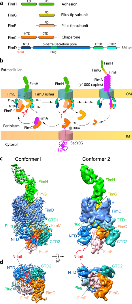
Type 1 pili are helical structures composed of the major pilus subunit FimA, with a distal tip composed of FimF, FimG, and the FimH adhesin at the very tip (Fig. 1a–b). FimH binds to mannosylated glycoproteins on the host bladder, thereby enabling the microbe to gain a foothold for infection 6. Two key concepts have been established for chaperone-usher mediated pilus biogenesis 3,7. First, pilus subunits comprise an incomplete immunoglobin-like fold that lacks the seventh β-strand present in canonical Ig folds. As nascent pilus subunits enter the periplasm via the Sec translocon, the FimC chaperone stabilizes each subunit by donating its G1 β-strand to complete the Ig fold of the subunit, in a mechanism termed donor strand complementation (DSC) (Extended Data Fig. 1) 8,9. Second, pilus subunits polymerize at the FimD usher via a donor strand exchange (DSE) mechanism, in which the G1 β-strand of the chaperone is replaced by the N-terminal extension (NTE) of an incoming pilus subunit (Extended Data Fig. 1) 10,11. Polymerization of the pilus fiber is driven by the folding energy differential of the DSC versus DSE β-strand insertions.
Figure 1. The missing link in pilus biogenesis and cryo-EM of FimD-tip complex.
(a) FimD-tip components. LD: Lectin domain. PD: Pilin domain. N-tail: 24 residues preceding the FimD folded NTD. (b) A partial pilus biogenesis sketch. The red arrows and question marks highlight a key unknown step – the NTD-to-CTDs handover of the chaperone-subunit. DsbA catalyzes disulfide bond formation in a nascent subunit, a prerequisite for subunit recognition by FimC 23. (c,d) The cryo-EM 3D map of Conformer 1 at 4.0 Å resolution (c) and of Conformer 2 at 5.1 Å resolution (d), respectively. Subunits are individually colored as in (a).
The FimD usher catalyzes ordered pilus biogenesis at the bacterial outer membrane (Fig. 1b) 12. The usher β-barrel domain functions as a protein secretion channel and is occluded by a plug domain in the resting (apo) state 13. Following FimC-FimH (FimCH) recruitment to the FimD NTD 14,15, the plug exits the channel and moves to the periplasm, adjacent to the NTD. The differential affinity of the usher for chaperone-subunit complexes, coupled with the unique capacity of the FimH adhesin to activate the usher, ensures pilus assembly in an ordered fashion 12,16,17. The kinetics of DSE between pilus subunits also plays an important role in determining subunit incorporation order 18,19. In the crystal structure of a FimDCH ternary complex, FimCH has dissociated from the FimD NTD and is bound to the FimD CTDs 13. In the crystal structure of a FimD-tip (FimD-CFGH) complex, the last incorporated subunit, FimF, in complex with FimC, is similarly bound to the CTDs 20. Clearly, there is a handover event during pilus assembly in which a chaperone-subunit recruited to the usher NTD transfers to the CTDs where pilus translocation occurs 13,20,21. However, the mechanism of this handover and its timing with respect to subunit polymerization – DSE of the incoming subunit with the preceding subunit – has been unknown.
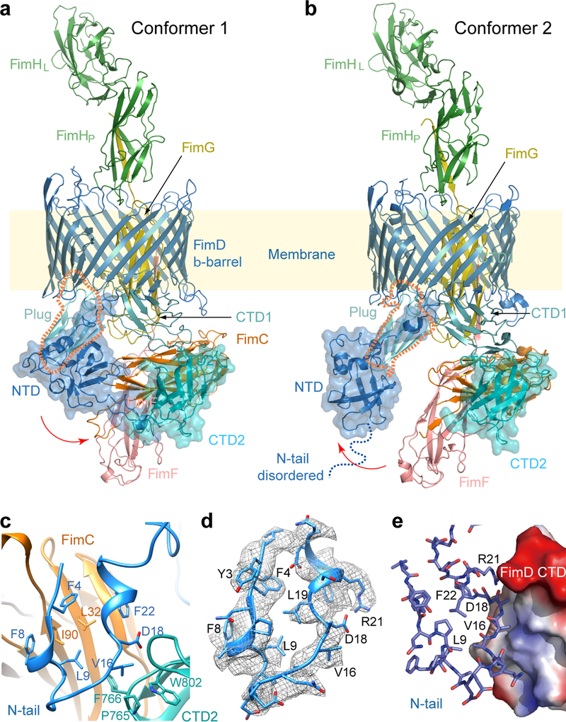
To address these questions, we derived two cryo-EM 3D maps of the FimD-tip complex: one at 4.0 Å resolution termed Conformer 1 and the other at 5.1 Å resolution termed Conformer 2 (Fig. 1c–d, Extended Data Figs. 2–3, Extended Data Table 1, SI Video 1). Atomic models were built using available component crystal structures (Fig. 2a–b). As expected, both Conformers consist of three pilus subunits bound to FimD: the FimH adhesin, which has crossed the usher channel to the extracellular face, FimG still inside the FimD chamber, and FimF in complex with the FimC chaperone on the periplasmic face. Also resolved in the 3D maps are the FimD plug domain, NTD, CTD1 and CTD2, all on the periplasmic side of the FimD β-barrel.
Figure 2. Atomic models of Conformers 1 and 2.
(a,b) Cryo-EM structures of the FimD-tip complex in Conformer 1 (a) and Conformer 2 (b), colored as in Fig. 1a. The dashed orange shape highlights the plug, which contacts the NTD in Conformer 2 but loses contact in Conformer 1 (see Extended Data Fig. 7). (c) Interactions between FimD N-tail and CTD2 in cartoon view. (d) Electron density for the FimD N-tail, with a local resolution of 4 Å. (e) FimD N-tail in cartoon view interacting with FimD CTD2 in surface-charge view, ranging from the blue positive to red negative charges.
Conformer 2 is similar to the previous crystal structure in which FimF, FimG, and FimH have polymerized into a tip fiber; i.e., the FimF and FimG NTEs are engaged in DSE with FimG and FimH, respectively, and FimCF has already transferred to the FimD CTDs 20. In Conformer 2, the FimD NTD makes no interactions with FimCF, residing ~10 Å away in a pose ready to recruit the next incoming chaperone-subunit complex (Fig. 2b). In this conformation, the FimD N-tail is not visible, likely due to flexibility, which is in agreement with previous structures of the disengaged NTD 13,14,20.
Conformer 1 reveals a previously undetected interaction between the usher NTD and CTD2. All of the usher periplasmic domains exhibit conformational changes as compared to Conformer 2 (Extended Data Fig. 4, SI Video 2). The FimD NTD shifts laterally by ~30 Å and rotates by ~45°, to interact with CTD2. This NTD shift leads to a loss of contact with the plug (Extended Data Fig. 5). The movement of the NTD causes the bound FimCF to move upwards by ~5 Å. To accommodate the NTD and FimCF movement, the remaining periplasmic components (plug, CTD1 and CTD2) also undergo significant rigid-body movements by ~10 Å. Due to these movements, interactions between FimCF and the FimD CTDs in Conformer 1 are much weaker than those in Conformer 2, consistent with the transitional nature of Conformer 1 (Extended Data Fig. 5). Thus, Conformer 1 captures the usher in the midst of the handover process, at a stage that appears to be immediately after incorporation of FimF into the nascent pilus tip; i.e., FimF has already engaged in DSE with FimG (Fig. 2a–b). We therefore conclude that subunit polymerization via the formation of DSE precedes release of the incoming subunit from the usher NTD.
Importantly, the FimD N-tail in Conformer 1 folds into a U-shape to interact with CTD2 and FimC (Fig. 2c–d). The N-tail binds to FimC via extensive hydrophobic interactions: Phe4, Phe8, Leu9, and Phe22 of the N-tail interact with Leu32 and Ile90 of FimC. Previous crystal structures of the isolated FimD NTD showed that these same residues participate in the NTD-FimC-subunit interface 14,22. Point mutations of these residues or deletions within the N-tail disrupt pilus biogenesis (Extended Data Table 2) 14,15. Interactions between the N-tail and CTD2 are of a mixed nature: Leu9 and Val16 are in proximity to and may interact hydrophobically with Pro765 and Phe766 of CTD2, and Asp18 may interact with Trp802 of CTD2. A FimD L9E mutant was unable to assemble type 1 pili on the bacterial surface and P765E and F766E mutants exhibited partial pilus assembly defects, as assessed by a hemagglutination assay (Extended Data Table 2). Although it may not directly contact the FimD N-tail, Trp802 and Pro765 seem to form a hydrophobic network with Val16 of the N-tail. The residues involved in contact between the FimD NTD and CTD2 are well conserved among usher proteins 5 (Extended Data Fig. 6).
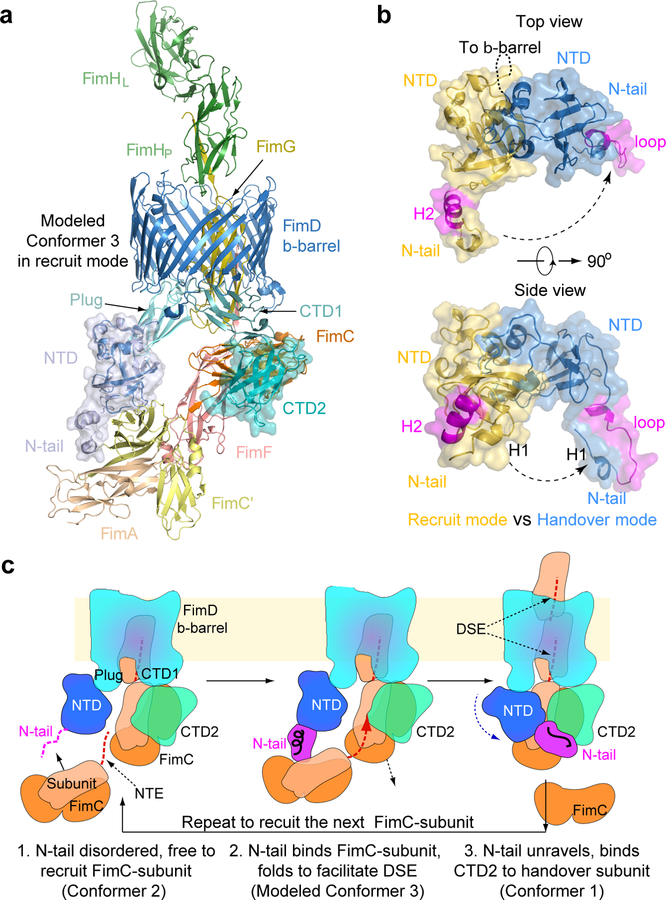
FimF is the last tip subunit, followed by incorporation of many FimA’s to form the pilus rod. Using crystal structures of FimCA and FimDNTD-FimCF 22,23, we built an atomic model of FimD-FimCFGH-FimCA, termed Conformer 3, to show how FimA is recruited to the FimD-tip complex 20 (Fig. 3a). In this recruitment mode, the N-tail of the FimD NTD is folded into a two-helix motif 14,22. Comparing Conformers 3 and 1 reveals the nature of FimD conformational changes during the handover process (Fig. 3b): the folded NTD core undergoes a rigid-body movement and dissociates from FimCF, while the FimD N-tail maintains contact with FimCF but changes from the helical motif to a loop, exposing several residues to interact with CTD2. Despite these changes, contacts between the N-tail and FimCF are similar in both conformers. This is possible because the N-tail is connected to the NTD by a flexible linker, allowing the NTD to rotate away from FimCF while the N-tail remains bound (Extended Data Fig. 7). Thus, the NTD is able to maintain contact with FimCF throughout the handover process while allowing the CTDs access to the common binding surface on FimC, permitting transfer of FimCF to the CTDs.
Figure 3. The FimD N-tail adopts three conformations during a subunit-incorporation cycle.
(a) Modeled Conformer 3 in which FimA (wheat) bound to a FimC’ chaperone (yellow) is being recruited by the FimD-tip complex. In the recruitment phase, the FimD N-tail is folded as a helical motif. (b) Comparison of FimD NTD and N-tail in Conformers 1 and 3 by superimposing the FimD β-barrel. (c) A 3-step NTD-to-CTDs handover mechanism of FimC-subunit at the usher, highlighting the three conformations of the FimD N-tail: disordered in Step 1, helical in Step 2, and a loop in Step 3. See text for details.
Our work reveals a previously unrecognized folding-unfolding cycle of the FimD N-tail: disordered in Conformer 2 (Fig. 2b); adopting a small helical motif in Conformer 3 (Fig. 3a); and rearranging to an ordered loop in Conformer 1 (Fig. 2a). Based on this observation, we propose an enhanced pilus assembly mechanism (Fig. 3c). In recruitment mode, the FimD N-tail likely swings freely in search of an incoming chaperone-subunit complex. Once captured, the N-tail folds into a helical motif to position the captured chaperone-subunit for DSE with the previously recruited subunit on the CTDs, leading to polymerization of the new subunit and displacement of the chaperone from the preceding subunit. The NTD-to-CTDs handover of the newly incorporated chaperone-subunit is then driven by the higher affinity of the CTDs for the shared binding site on FimC 24, together with formation of the new N-tail interface with CTD2. Formation of this interface may also allow CTD2 to facilitate the handover process by destabilizing chaperone-subunit binding to the NTD 25. Maintenance of N-tail binding to the newly recruited chaperone-subunit throughout the handover process allows transfer of the complex to the CTDs without complete release from the NTD. This provides a mechanism to impose directionality to subunit polymerization at the usher, ensuring outward translocation of the pilus fiber. Once the growing pilus end is handed over to the CTDs, release of the N-tail from CTD2 may be facilitated by binding of the NTD to the plug domain, resetting the usher for a new cycle of chaperone-subunit recruitment and polymerization. Thus, like an ouroboros, the catalytic cycle involves a meeting between the two extremities of the usher.
The capture of Conformers 1 and 2 in the same solution indicates that they exist in a dynamic equilibrium. It is conceivable that Conformer 1, in which the NTD swings over to bind CTD2, stabilizes the FimC chaperone against dissociation from the end of the growing pilus fiber. Dissociation of the chaperone would risk release of the pilus fiber and diffusion through the usher pore into the extracellular medium. This stabilization function of the usher NTD would be absent in Conformer 2. However, because the two conformers are in equilibrium, Conformer 2 likely reverts back to Conformer 1 faster than FimC spontaneously dissociates from the pilus end. In this regard, Conformer 1 may play a dual function: providing a mechanism for handing over the growing pilus end from the usher NTD to the CTDs, and functioning to stabilize the growing pilus fiber from diffusion away from the usher.
METHODS
FimD-tip complex expression and purification.
The His-tagged FimD-tip complex (FimDCFGH) was expressed in E. coli Tuner competent cells as previously described 26. 60 L of FimDCFGH was grown at 37 °C with aeration in LB supplemented with 50 μg/mL kanamycin and 25 μg/mL chloramphenicol. At OD600 = 0.6, FimDCFGH was induced with 25 μM IPTG and 0.05% (w/v) arabinose overnight at 20 °C. The bacteria were harvested and resuspended using a homogenizer into 25 mM Tris-HCl (pH 8.0), 100 mM NaCl, 1 mM β-ME. The cells were disrupted with sonication or by a microfluidizer. The volume was made to 1.8 L using 25 mM Tris-HCl (pH 8.0), 100 mM NaCl, 1 mM β-ME. The disrupted cells were spun (10,000 x g, 20 min, 4 °C) to separate cellular debris and unbroken cells. 0.5% (w/v) Sarkosyl was added to the supernatant to solubilize the inner membrane (stirring, 20 min, room temperature). The outer membrane was isolated by ultracentrifugation (100,000 x g, 50 min, 4 °C). The outer membrane was washed three times using 25 mM Tris-HCl (pH 8.0), 100 mM NaCl, 1 mM β-ME and ultracentrifugation was used to isolate the pure outer membrane complex. The outer membrane was resuspended using 25 mM Tris-HCl (pH 8.0), 300 mM NaCl, 15% glycerol, 10 mM MgCl2, and protease inhibitors. FimDCFGH was extracted by adding 30 mg of lysozyme and 1% (w/v) n-Dodecyl β-D-maltoside (DDM; Anatrace) (stirring, overnight, 4 °C). The insoluble material was separated out by ultracentrifugation (100,000 x g, 1 h, 4 °C). The solubilized FimDCFGH was applied to a Ni-NTA column and washed several times with 25 mM Tris-HCl (pH 8.0), 300 mM NaCl, 0.5% DDM. The Ni-NTA column was washed with 50 mM buffer containing imidazole for removal of impurities. FimDCFGH was eluted using buffer containing 250 mM imidazole. Purified FimDCFGH was concentrated using a Centricon 100 concentrator. The concentrated sample was applied on a size-exclusion chromatography column Superdex 200 (GE Healthcare) equilibrated with 25 mM Tris-HCl (pH 8.0), 200 mM NaCl, 0.5% DDM. The fractions of the size-exclusion chromatography were analyzed on SDS-PAGE (Extended Data Fig. 2a,b). The non-aggregated fractions containing the FimDCFGH complex were concentrated.
Cryo-EM.
To prepare cryo-EM grids, a 3 μl FimDCFGH sample was applied to glow-discharged C-flat 1.2/1.3 holey carbon grids, incubated for 10 s at 6 °C and 95% humidity, blotted for 3 s then plunged into liquid ethane using an FEI Vitrobot IV. In C-flat R1.2/1.3 holey carbon film grids, the FimDCFGH particles distributed well with no aggregation problem. The grids were loaded into an FEI Titan Krios electron microscope operated at a high tension of 300 KV and collected images semi-automatically with EPU under low-dose mode at a nominal magnification of ×130,000 and a pixel size of 1.09 Å per pixel. A Gatan K2 summit direct electron detector was used under super-resolution mode for image recording with an under-focus range from 1.5 to 2.5 μm. A Bioquantum energy filter installed in front of the K2 detector was operated in the zero-energy-loss mode with an energy slit width of 20 eV. The dose rate was 10 electrons per Å2 per second and total exposure time was 6 s. The total dose was divided into a 30-frame movie so each frame was exposed for 0.2 s.
Image processing and 3D reconstruction.
Approximately 12,000 raw movie micrographs were collected. The movie frames were first aligned and superimposed by the program Motioncorr 2.0 27. Contrast transfer function parameters of each aligned micrograph were calculated using the program CTFFIND4 28. All the remaining steps, including particle auto selection, 2D classification, 3D classification, 3D refinement, and density map post-processing were performed using Relion-2.1 29. Template for automatic picking was generated from a 2D average of about ~10,000 manually picked particles in different views. Automatic particle selection was performed for the entire data set, and 1,534,108 particles were initially picked. Selected particles were carefully inspected; “bad” particles were removed, some initially missed “good” particles were re-picked, and the remaining good particles were sorted by similarity to the 2D references, in which the bottom 10% of particles with the lowest z-scores were removed from the particle pool. 2D classification of all good particles was performed and particles in the classes with unrecognizable features by visual inspection were removed. A total of 758,698 particles were used for further 3D classification. Five 3D models from the dataset were derived, and the two best models were chosen for final refinement (Extended Data Fig. 2c–e). The other three models were distorted and those particles were discarded. The final two datasets have 250,370 and 166,913 particles respectively. They were used for further 3D refinement, resulting in the 4.0 Å and 5.1 Å 3D density map. The resolution of the map was estimated by the gold-standard Fourier shell correlation, at the correlation cutoff value of 0.143. The 3D density map was sharpened by applying a negative B-factor of −230 and −241 Å2, respectively (Extended Data Fig. 3a–b).
Atomic modeling, refinement, and validation.
The modeling of two conformations was based on the crystal structure of FimDCFGH (PDB ID 4J3O). For Conformation I, the complex structure (PDB ID 4J3O) was split into individual subunits and individually docked into the EM map using Chimera 30. The N-terminal tail region (2–27 aa) of FimD was absent from the FimDCFGH structure and its model was obtained from FimD_NTD-FimCF structure (PDB ID 3BWU), which was fitted into the map using Chimera. The initial modeling was followed by further manual adjustments using COOT 31, guided by residues with bulky side chains like Arg, Phe, Tyr and Trp (Extended Data Fig. 3c). The improved model was refined in real space against EM densities using the phenix.real_space_refine module in PHENIX 32. For Conformation II, Chimera was used to rigid-body dock the whole structure of FimDCFGH (PDB ID 4J3O) into the corresponding EM map, fitting well into the densities. Only FimH was separated and individually rigid-body fitted into the density using Chimera. Due to the low resolution of this conformation, the structure was not subject to further refinement. The FimD-tip Conformer 3 was modeled by (1) superimposing the NTD in the FimD_NTD-FimCF structure (PDB ID: 3BWU) with the FimD_NTD in FimD-tip Conformer 2, and (2) superimposing FimC in the FimCA structure (PDB ID: 4DWH) with FimC in the FimD_NTD-FimCF complex. Finally, the atomic model of Conformer 1 was validated using MolProbity 33. Structural figures were prepared in Chimera and Pymol (https://www.pymol.org)
FimD mutagenesis and hemagglutination assay.
For construction of the FimD L9E, V16E, P765E, and F766E mutants, plasmid pETS4 16 was mutated using the QuikChange Site-Directed Mutagenesis Kit (Stratagene) and primers as follows: L9E, 5’-CCGACCTCTATTTTAATCCGCGCTTTGAAGCGGATGATCC-3’; V16E, 5’-GGATGATCCCCAGGCTGAGGCCGATTTATCG-3’; P765E, 5’-CCACAATAATAAGCCGCTGGAGTTTGGGGCGATGGTGAC-3’; and F766E, 5’-CCACAATAATAAGCCGCTGCCGGAGGGGGCGATGGTGAC-3’. Proper expression and folding of the FimD mutants in the bacterial outer membrane were determined by heat-modifiable mobility, as described 34. Comparison of the mutants with wild-type FimD for ability to assemble type 1 pili on the bacterial surface was performed using a hemagglutination assay, as described 34. Hemagglutination titers were recorded visually as the greatest fold dilution of bacteria able to agglutinate guinea pig red blood cells (Colorado Serum Company). Titers were calculated from three independent experiments of three replicates each.
Extended Data
Extended Data Figure 1. Pilus assembly occurs via donor-strand complementation (DSC) and donor-strand exchange (DSE).
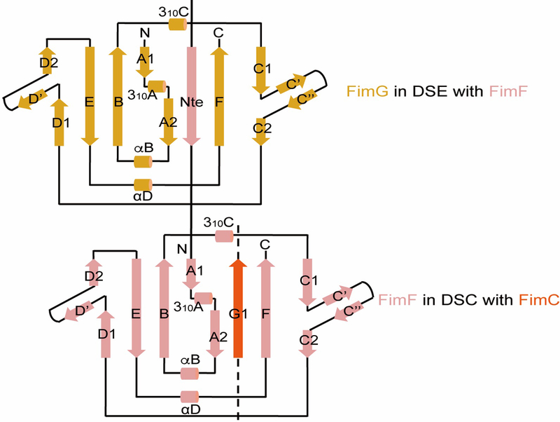
This sketch is based on the crystal structure of FimDCFGH (PDB ID 4J3O). DSC: Pilus subunits (FimF in this case) have an immunoglobulin (Ig)-like structure, but with the C-terminal G strand missing. In the periplasm, the chaperone FimC donates its G1 strand to complete the subunit fold, but in a non-canonical parallel orientation with the subunit F strand. DSE: The donor strand of the FimC chaperone in the previous subunit (FimG in this case) is replaced by the N-terminal extension (NTE) of the incoming subunit, FimF, completing the FimG subunit Ig fold in a canonical, anti-parallel orientation.
Extended Data Figure 2. Cryo-EM of FimD-tip complex.
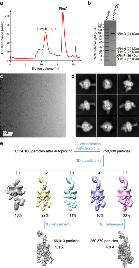
(a) The gel filtration profile of FimDCFGH complex from a Superdex 200 10/300GL column. (b) Coomassie blue SDS–PAGE gel of the peak fraction showing the presence of all subunits of the purified FimDCFGH complex. Similar sample preparation by gel filtration and SDS-PAGE examination were carried out more than 3 times. (c) A raw cryo-EM micrograph of the purified FimD-tip complexes embedded in vitreous ice. A total of 12,000 such micrographs were recorded. (d) Selected 2D class averages showing the presence of many different views and well resolved structural features. Over 750,000 raw particles contributed to final 2D class averages. (e) 3D classification scheme. Over 1 million raw particles were selected from drift-corrected electron micrographs. 2D and 3D classification resulted in two 3D maps that were of the expected shape and the structure appeared complete, and the other three maps were either partial structures or distorted. Refinement with ~250,370 particles led to the 4.0-Å resolution 3D map of Conformer 1, and ~166,913 particles led to the 5.1-Å resolution 3D map of Conformer 2.
Extended Data Figure 3. Resolution estimation and selected regions of the 3D EM maps.
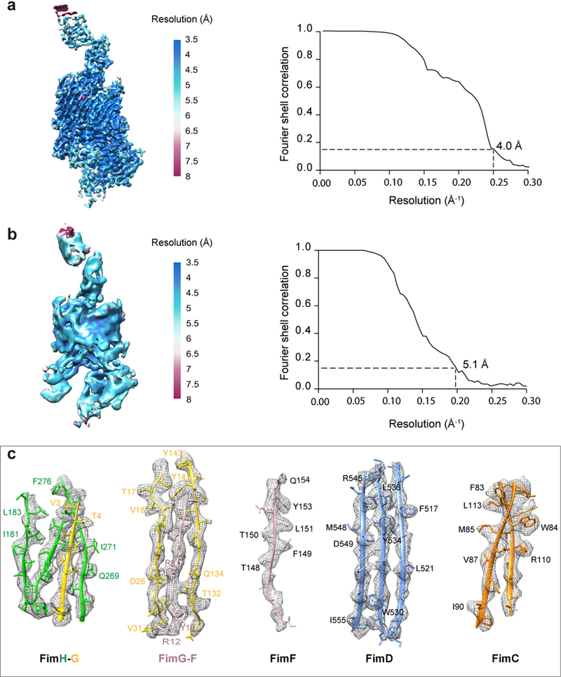
(a) Local resolution estimation and the Gold-standard Fourier shell correlation estimation at the 0.143 correlation threshold of the FimD-tip in Conformer 1. (b) The same for Conformer 2. (c) Model fitting in the FimDCFGH density map. Selected densities for FimH-G, FimG-F, FimF, FimD, FimC of Conformer I are shown. Amino acids with clear side-chain densities are indicated.
Extended Data Figure 4. Comparison between Conformer 1 and Conformer 2 of the FimD-tip complex.
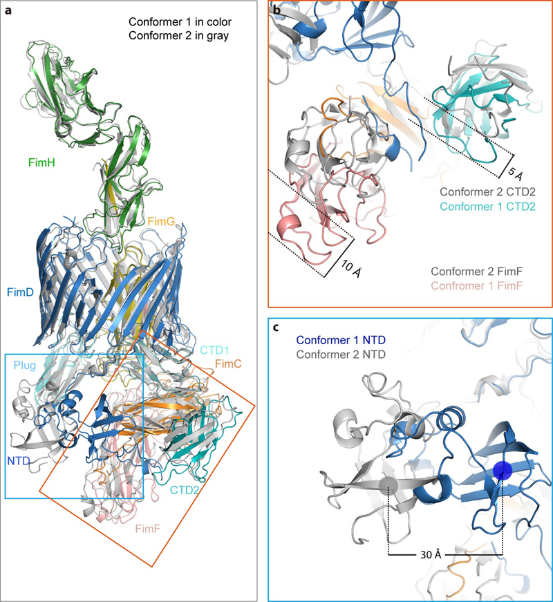
(a) Overlap of FimD-Tip Conformer 1 in color cartoon with that of the FimD-Tip Conformer 2 in gray cartoon. The NTD movement is labeled in the blue box, and the CTD and FimF movement is labeled in the orange box. (b) Comparison of FimF and CTD2 of Comformer 1 with Conformer 2. FimF and CTD2 shift 10 Å and 5 Å, respectively. (c) Comparison of NTD of Comformer 1 with Conformer 2. The NTD shifts laterally by ~30 Å and rotated by ~45°.
Extended Data Figure 5. Comparison of interaction between FimD plug domain and NTD (a) and between FimD CTDs and FimCF (b) in Conformers 1 and 2 by superimposing the two conformations.
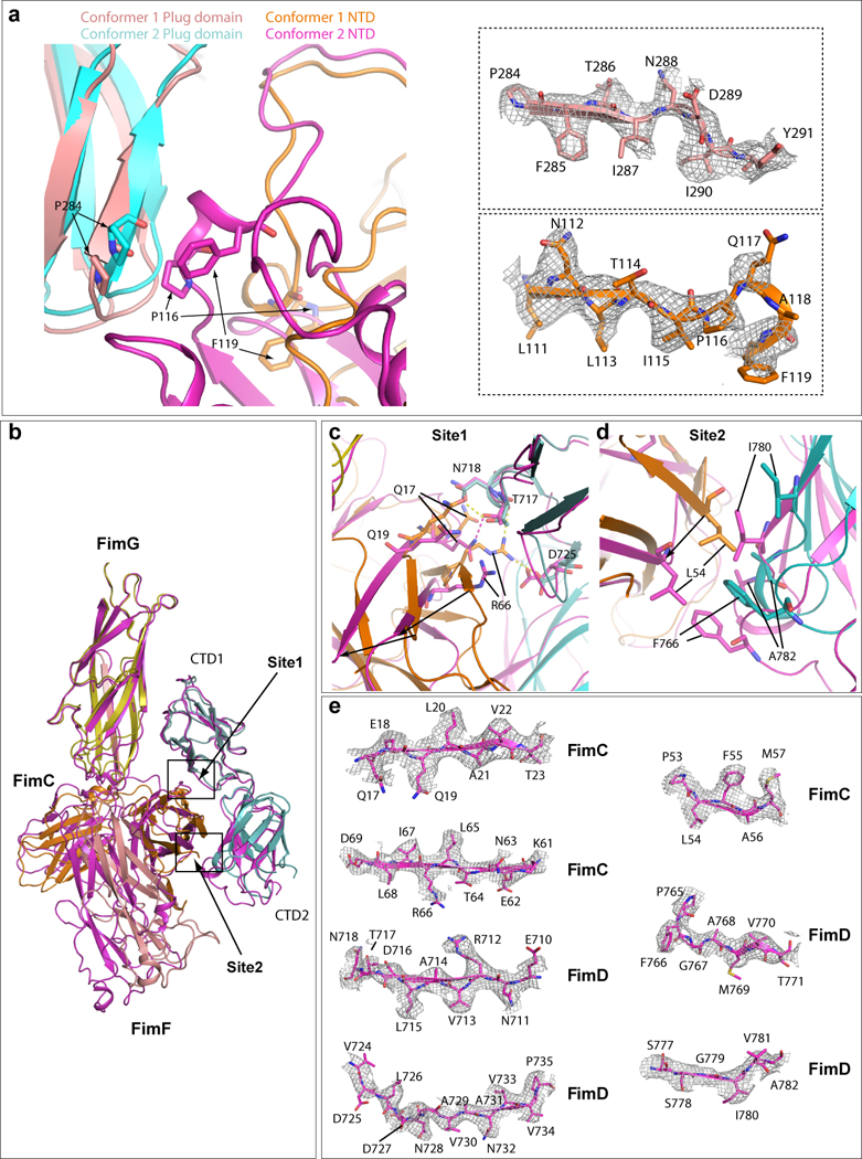
The Plug domain and NTD of Conformer 1 are colored in salmon and orange, respectively, and Plug domain and NTD of Conformer 2 in cyan and magenta, respectively. In the right side, electron densities of regions involved in the interaction in Conformer I are shown in the top panel (FimD plug) and bottom panel (FimD NTD). Some amino acids have clear side-chain densities. (b) Superimposition of FimD_CTDs-FimCF in Conformers 1 (magenta). and 2 (colored as in Fig. 3). (c) Detailed interactions in Site 1. Extensive interactions are present in Conformer 2. Much weaker interactions are present in conformer 1 (between Q17 and T717). (d) Detailed interactions in Site 2 (marked in panel a). In Conformer 2, hydrophobic interactions exist between FimC L54 and FimD F766, and between I780 and A782. Much weaker interactions are present in Conformer 1. (e) The electron densities in regions involved in Sites 1 and 2 interactions between FimC and FimD in Conformer 1. Some amino acids have side-chain densities.
Extended Data Figure 6. Sequence conservation of the interacting interface at the two extreme termini of the FimD usher.
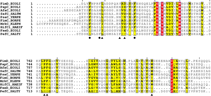
Residues involved in FimD NTD and FimC interaction are labeled with circles, and residues in FimD NTD and FimD CTD2 interaction are labeled with triangles.
Extended Data Figure 7. The interactions between FimD NTD and FimCF in Conformer 1 (a) and in modeled Conformer 3 (b).
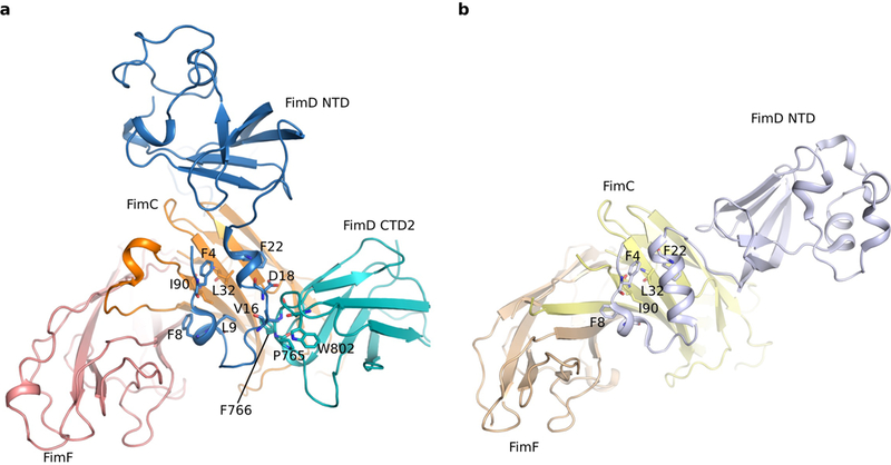
There are no interactions between the FimD NTD and FimF subunit in either conformer. The interactions between the FimD N-tail and the FimC chaperone are essentially the same in the two conformers.
Extended Data Table 1.
Cryo-EM data collection and model statistics of FimD-tip complex.
| Conformer 1 (EMD-8953) (PDB 6E14) |
Conformer 2 (EMD-8954) (PDB 6E15) |
|
|---|---|---|
| Data collection and processing | ||
| Magnification | 130,000 | 130,000 |
| Voltage (kV) | 300 | 300 |
| Electron dose (e−/Å2) | 50 | 50 |
| Defocus range (µm) | −1.5–−2.5 | −1.5–−2.5 |
| Pixel size (Å) | 1.09 | 1.09 |
| Symmetry imposed | C1 | C1 |
| Initial particle images (no.) | 758,698 | 758,698 |
| Final particle images (no.) | 250,370 | 166,913 |
| Map resolution (Å) | 4.0 | 5.1 |
| FSC threshold | 0.143 | 0.143 |
| Map resolution range (Å) | 3.5 – 5.0 | 4.0 – 6.0 |
| Refinement | ||
| Initial model used (PDB code) | 4J3O | 4J3O |
| Map sharpening B factor (Å2) | −230 | −241 |
| Model composition | ||
| Non-hydrogen atoms | 11995 | 11732 |
| Protein and DNA residues | 1572 | 1536 |
| Ligands | 0 | 0 |
| R.m.s. deviations | ||
| Bond lengths (Å) | 0.007 | |
| Bond angels (°) | 1.38 | |
| Validation | ||
| MolProbity score | 1.52 | |
| Clashscore | 3.92 | |
| Poor rotamers (%) | 0.23 | |
| Ramachandran plot | ||
| Favored (%) | 95.04 | |
| Allowed (%) | 4.71 | |
| Disallowed (%) | 0.25 | |
Extended Data Table 2.
Effects of mutations in FimD N-tail and CTD2 on pilus assembly.
| FimD | Agglutination | Reference |
|---|---|---|
| wild-type | 128±0a, +b | This study, 14 |
| F4A | 0, − | 14,34 |
| F8A | +/− | 14 |
| L9E | 0±0 | This study |
| Δ1–11 | – | 14 |
| V16E | 128±0 | This study |
| F22A | – | 14 |
| P765E | 64±0 | This study |
| F766E | 64±0 | This study |
Hemagglutination titers represent the highest-fold dilution of bacteria able to agglutinate guinea pig red blood cells. The values report on effects of the usher mutations on overall bacterial pilus production. A titer of 128 equals a 7-fold dilution and a titer of 64 equals a 6-fold dilution. Titers were calculated from three independent experiments of three replicates each; all values for each of the experiments and replicates were identical. The functional defects of the FimD L9E, P765E and F766E mutants were not due to changes in expression or folding in the outer membrane, as determined by a heat-modifiable mobility assay.
Ability of bacteria to agglutinate yeast cells: (+), strong agglutination; (+/−), weak agglutination; (–), no agglutination.
Supplementary Material
ACKNOWLEDGEMENTS
Cryo-EM data was collected at the David Van Andel Advanced Cryo-Electron Microscopy Suite at the Van Andel Research Institute. We thank Xing Meng for help with data collection. We thank the anonymous referee for pointing out the pilus stabilization function of Conformer 1. This study was supported by the US National Institutes of Health R01 grants GM062987 (to D.G.T. and H.L.) and GM111742 (to H.L.) and Van Andel Research Institute (to H.L.).
Footnotes
COMPETING INTERESTS
The authors declare no competing financial interests.
DATA AVAILABILITY. The cryo-EM 3D maps of the FimD-tip (FimDCFGH) complex have been deposited at the EMDB database with accession codes EMD-8953 (Conformer 1) and EMD-8954 (Conformer 2), and their corresponding atomic models were deposited at the RCSB PDB with accession codes 6E14 (Conformer 1) and 6E15 (Conformer 2), respectively.
REFERENCES
- 1.Flores-Mireles AL, Walker JN, Caparon M & Hultgren SJ Urinary tract infections: epidemiology, mechanisms of infection and treatment options. Nat Rev Microbiol 13, 269–284, doi: 10.1038/nrmicro3432 (2015). [DOI] [PMC free article] [PubMed] [Google Scholar]
- 2.Thanassi DG, Saulino ET & Hultgren SJ The chaperone/usher pathway: a major terminal branch of the general secretory pathway. Curr Opin Microbiol 1, 223–231 (1998). [DOI] [PubMed] [Google Scholar]
- 3.Geibel S & Waksman G The molecular dissection of the chaperone-usher pathway. Biochim Biophys Acta 1843, 1559–1567, doi: 10.1016/j.bbamcr.2013.09.023 (2014). [DOI] [PubMed] [Google Scholar]
- 4.Zav’yalov V, Zavialov A, Zav’yalova G & Korpela T Adhesive organelles of Gram-negative pathogens assembled with the classical chaperone/usher machinery: structure and function from a clinical standpoint. FEMS Microbiol Rev 34, 317–378, doi: 10.1111/j.1574-6976.2009.00201.x (2010). [DOI] [PubMed] [Google Scholar]
- 5.Nuccio SP & Baumler AJ Evolution of the chaperone/usher assembly pathway: fimbrial classification goes Greek. Microbiol Mol Biol Rev 71, 551–575, doi: 10.1128/MMBR.00014-07 (2007). [DOI] [PMC free article] [PubMed] [Google Scholar]
- 6.Mulvey MA et al. Induction and evasion of host defenses by type 1-piliated uropathogenic Escherichia coli. Science 282, 1494–1497 (1998). [DOI] [PubMed] [Google Scholar]
- 7.Sauer FG et al. Chaperone-assisted pilus assembly and bacterial attachment. Curr Opin Struct Biol 10, 548–556 (2000). [DOI] [PubMed] [Google Scholar]
- 8.Choudhury D et al. X-ray structure of the FimC-FimH chaperone-adhesin complex from uropathogenic Escherichia coli. Science 285, 1061–1066 (1999). [DOI] [PubMed] [Google Scholar]
- 9.Sauer FG et al. Structural basis of chaperone function and pilus biogenesis. Science 285, 1058–1061 (1999). [DOI] [PubMed] [Google Scholar]
- 10.Zavialov AV et al. Structure and biogenesis of the capsular F1 antigen from Yersinia pestis: preserved folding energy drives fiber formation. Cell 113, 587–596 (2003). [DOI] [PubMed] [Google Scholar]
- 11.Sauer FG, Pinkner JS, Waksman G & Hultgren SJ Chaperone priming of pilus subunits facilitates a topological transition that drives fiber formation. Cell 111, 543–551 (2002). [DOI] [PubMed] [Google Scholar]
- 12.Nishiyama M, Ishikawa T, Rechsteiner H & Glockshuber R Reconstitution of pilus assembly reveals a bacterial outer membrane catalyst. Science 320, 376–379, doi: 10.1126/science.1154994 (2008). [DOI] [PubMed] [Google Scholar]
- 13.Phan G et al. Crystal structure of the FimD usher bound to its cognate FimC-FimH substrate. Nature 474, 49–53, doi: 10.1038/nature10109 (2011). [DOI] [PMC free article] [PubMed] [Google Scholar]
- 14.Nishiyama M et al. Structural basis of chaperone-subunit complex recognition by the type 1 pilus assembly platform FimD. EMBO J 24, 2075–2086, doi: 10.1038/sj.emboj.7600693 (2005). [DOI] [PMC free article] [PubMed] [Google Scholar]
- 15.Ng TW, Akman L, Osisami M & Thanassi DG The usher N terminus is the initial targeting site for chaperone-subunit complexes and participates in subsequent pilus biogenesis events. J Bacteriol 186, 5321–5331, doi: 10.1128/JB.186.16.5321-5331.2004 (2004). [DOI] [PMC free article] [PubMed] [Google Scholar]
- 16.Saulino ET, Thanassi DG, Pinkner JS & Hultgren SJ Ramifications of kinetic partitioning on usher-mediated pilus biogenesis. EMBO J 17, 2177–2185, doi: 10.1093/emboj/17.8.2177 (1998). [DOI] [PMC free article] [PubMed] [Google Scholar]
- 17.Volkan E et al. Domain activities of PapC usher reveal the mechanism of action of an Escherichia coli molecular machine. Proc Natl Acad Sci U S A 109, 9563–9568, doi: 10.1073/pnas.1207085109 (2012). [DOI] [PMC free article] [PubMed] [Google Scholar]
- 18.Nishiyama M & Glockshuber R The outer membrane usher guarantees the formation of functional pili by selectively catalyzing donor-strand exchange between subunits that are adjacent in the mature pilus. J Mol Biol 396, 1–8, doi: 10.1016/j.jmb.2009.12.005 (2010). [DOI] [PubMed] [Google Scholar]
- 19.Rose RJ et al. Unraveling the molecular basis of subunit specificity in P pilus assembly by mass spectrometry. Proc Natl Acad Sci U S A 105, 12873–12878, doi: 10.1073/pnas.0802177105 (2008). [DOI] [PMC free article] [PubMed] [Google Scholar]
- 20.Geibel S, Procko E, Hultgren SJ, Baker D & Waksman G Structural and energetic basis of folded-protein transport by the FimD usher. Nature 496, 243–246, doi: 10.1038/nature12007 (2013). [DOI] [PMC free article] [PubMed] [Google Scholar]
- 21.Allen WJ, Phan G, Hultgren SJ & Waksman G Dissection of pilus tip assembly by the FimD usher monomer. J Mol Biol 425, 958–967, doi: 10.1016/j.jmb.2012.12.024 (2013). [DOI] [PMC free article] [PubMed] [Google Scholar]
- 22.Eidam O, Dworkowski FS, Glockshuber R, Grutter MG & Capitani G Crystal structure of the ternary FimC-FimF(t)-FimD(N) complex indicates conserved pilus chaperone-subunit complex recognition by the usher FimD. FEBS Lett 582, 651–655, doi: 10.1016/j.febslet.2008.01.030 (2008). [DOI] [PubMed] [Google Scholar]
- 23.Crespo MD et al. Quality control of disulfide bond formation in pilus subunits by the chaperone FimC. Nat Chem Biol 8, 707–713, doi: 10.1038/nchembio.1019 (2012). [DOI] [PubMed] [Google Scholar]
- 24.Werneburg GT et al. The pilus usher controls protein interactions via domain masking and is functional as an oligomer. Nat Struct Mol Biol 22, 540–546, doi: 10.1038/nsmb.3044 (2015). [DOI] [PMC free article] [PubMed] [Google Scholar]
- 25.Volkan E et al. Molecular basis of usher pore gating in Escherichia coli pilus biogenesis. Proc Natl Acad Sci U S A 110, 20741–20746, doi: 10.1073/pnas.1320528110 (2013). [DOI] [PMC free article] [PubMed] [Google Scholar]
- 26.Remaut H et al. Fiber formation across the bacterial outer membrane by the chaperone/usher pathway. Cell 133, 640–652, doi: 10.1016/j.cell.2008.03.033 (2008). [DOI] [PMC free article] [PubMed] [Google Scholar]
- 27.Zheng SQ et al. MotionCor2: anisotropic correction of beam-induced motion for improved cryo-electron microscopy. Nat Methods 14, 331–332, doi: 10.1038/nmeth.4193 (2017). [DOI] [PMC free article] [PubMed] [Google Scholar]
- 28.Rohou A & Grigorieff N CTFFIND4: Fast and accurate defocus estimation from electron micrographs. J Struct Biol 192, 216–221, doi: 10.1016/j.jsb.2015.08.008 (2015). [DOI] [PMC free article] [PubMed] [Google Scholar]
- 29.Scheres SH RELION: implementation of a Bayesian approach to cryo-EM structure determination. J Struct Biol 180, 519–530, doi: 10.1016/j.jsb.2012.09.006 (2012). [DOI] [PMC free article] [PubMed] [Google Scholar]
- 30.Pettersen EF et al. UCSF Chimera--a visualization system for exploratory research and analysis. J Comput Chem 25, 1605–1612, doi: 10.1002/jcc.20084 (2004). [DOI] [PubMed] [Google Scholar]
- 31.Emsley P, Lohkamp B, Scott WG & Cowtan K Features and development of Coot. Acta Crystallogr D Biol Crystallogr 66, 486–501, doi: 10.1107/S0907444910007493 (2010). [DOI] [PMC free article] [PubMed] [Google Scholar]
- 32.Adams PD et al. PHENIX: a comprehensive Python-based system for macromolecular structure solution. Acta Crystallogr D Biol Crystallogr 66, 213–221, doi: 10.1107/S0907444909052925 (2010). [DOI] [PMC free article] [PubMed] [Google Scholar]
- 33.Chen VB et al. MolProbity: all-atom structure validation for macromolecular crystallography. Acta Crystallogr D Biol Crystallogr 66, 12–21, doi: 10.1107/S0907444909042073 (2010). [DOI] [PMC free article] [PubMed] [Google Scholar]
- 34.Henderson NS, Ng TW, Talukder I & Thanassi DG Function of the usher N-terminus in catalysing pilus assembly. Mol Microbiol 79, 954–967, doi: 10.1111/j.1365-2958.2010.07505.x (2011). [DOI] [PMC free article] [PubMed] [Google Scholar]
Associated Data
This section collects any data citations, data availability statements, or supplementary materials included in this article.


