

Abstract
In recent years new technologies in neuroscience have made it possible to measure the activities of large numbers of neurons simultaneously in behaving animals. For each neuron a fluorescence trace is measured; this can be seen as a first-order approximation of the neuron’s activity over time. Determining the exact time at which a neuron spikes on the basis of its fluorescence trace is an important open problem in the field of computational neuroscience.
Recently, a convex optimization problem involving an ℓ1 penalty was proposed for this task. In this paper we slightly modify that recent proposal by replacing the ℓ1 penalty with an ℓ0 penalty. In stark contrast to the conventional wisdom that ℓ0 optimization problems are computationally intractable, we show that the resulting optimization problem can be efficiently solved for the global optimum using an extremely simple and efficient dynamic programming algorithm. Our R-language implementation of the proposed algorithm runs in a few minutes on fluorescence traces of 100,000 timesteps. Furthermore, our proposal leads to substantial improvements over the previous ℓ1 proposal, in simulations as well as on two calcium imaging datasets.
R-language software for our proposal is available on CRAN in the package LZeroSpikeInference. Instructions for running this software in python can be found at https://github.com/jewellsean/LZeroSpikeInference.
Keywords: Neuroscience, calcium imaging, changepoint detection, dynamic programming
1. Introduction.
When a neuron spikes, calcium floods the cell. In order to quantify intracellular calcium levels, calcium imaging techniques make use of fluorescent calcium indicator molecules [Ahrens et al. (2013), Dombeck et al. (2007), Prevedel et al. (2014)]. Thus, a neuron’s fluorescence trace can be seen as a first-order approximation of its activity level over time.
However, the fluorescence trace itself is typically not of primary scientific interest; instead, it is of interest to determine the underlying neural activity, that is, the specific times at which the neuron spiked. Inferring the spike times on the basis of a fluorescence trace amounts to a challenging deconvolution problem, which has been the focus of substantial investigation [Deneux et al. (2016), Grewe et al. (2010), Pnevmatikakis et al. (2013), Sasaki et al. (2008), Theis et al. (2016), Vogelstein et al. (2009, 2010), Holekamp, Turaga and Holy (2008), Yaksi and Friedrich (2006), Friedrich and Paninski (2016), Friedrich, Zhou and Paninski (2017)]. In this paper we propose a new approach for this task, which is based upon the following insight, an autoregressive model for calcium dynamics that has been extensively studied in the neuroscience literature [Friedrich and Paninski (2016), Friedrich, Zhou and Paninski (2017), Vogelstein et al. (2010)] leads directly to a simple ℓ0 optimization problem for which an efficient and exact algorithm is available.
1.1. An autoregressive model for calcium dynamics.
In this paper we will revisit an autoregressive model for calcium dynamics that has been considered by a number of authors in the recent literature [Friedrich and Paninski (2016), Friedrich, Zhou and Paninski (2017), Pnevmatikakis et al. (2016), Vogelstein et al. (2010)]. We closely follow the notation of Friedrich, Zhou and Paninski (2017). This model posits that yt, the fluoresence at the tth timestep, is a noisy realization of ct, the unobserved underlying calcium concentration at the tth timestep. In the absence of a spike at the tth timestep (st = 0), the calcium concentration decays according to a pth-order autoregressive process. However, if a spike occurs at the tth timestep (st > 0), then the calcium concentration increases. Thus,
| (1) |
In (1), the quantities γ1, …, γp are the parameters in the autoregressive model. Note that the quantity yt in (1) is observed; all other quantities are unobserved. Since we would like to know whether a spike occurred at the tth timestep, the parameter of interest is st. Figure 1(a) displays a small dataset generated according to (1).
Fig. 1.
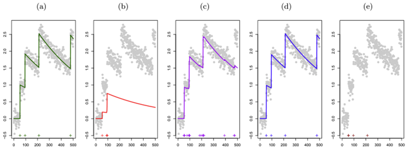
A toy simulated data example. In each panel the x-axis represents time. Observed fluorescence values are displayed in ( ). (a): Unobserved calcium concentrations (
 ) and true spike times (
 ). Data were generated according to the model (1). (b): Estimated calcium concentrations (
 ) and spike times (
 ) that result from solving the ℓ1
optimization problem (3) with the value of λ that yields the true number of spikes. This value of λ leads to very poor estimation of both the underlying calcium dynamics and the spikes. (c): Estimated calcium concentrations (
) that result from solving the ℓ1
optimization problem (3) with the value of λ that yields the true number of spikes. This value of λ leads to very poor estimation of both the underlying calcium dynamics and the spikes. (c): Estimated calcium concentrations ( ) and spike times (
 ) that result from solving the ℓ1
optimization problem (3) with the largest value of λ that results in at least one estimated spike within the vicinity of each true spike. This value of λ results in 19 estimated spikes, which is far more than the true number of spikes. The poor performance of the ℓ1
optimization problem in panels (b) and (c) is a consequence of the fact that the ℓ1
penalty performs shrinkage as well as spike estimation; this is discussed further in
Section 1.2. (d): Estimated calcium concentrations (
) that result from solving the ℓ1
optimization problem (3) with the largest value of λ that results in at least one estimated spike within the vicinity of each true spike. This value of λ results in 19 estimated spikes, which is far more than the true number of spikes. The poor performance of the ℓ1
optimization problem in panels (b) and (c) is a consequence of the fact that the ℓ1
penalty performs shrinkage as well as spike estimation; this is discussed further in
Section 1.2. (d): Estimated calcium concentrations ( ) and spike times (
 ) that result from solving the ℓ0
optimization problem (5). (e): The four spikes in panel (c) associated with the largest estimated increase in calcium (
) that result from solving the ℓ0
optimization problem (5). (e): The four spikes in panel (c) associated with the largest estimated increase in calcium ( ); we refer to this in the text as the post-thresholding ℓ1
estimator. Since the estimated calcium is not well defined after post-thresholding, we do not plot the estimated calcium concentration.
); we refer to this in the text as the post-thresholding ℓ1
estimator. Since the estimated calcium is not well defined after post-thresholding, we do not plot the estimated calcium concentration.
In what follows, for ease of exposition, we assume β0 = 0 and β1 = 1 in (1). This assumption is made without loss of generality, since β0 and β1 can be estimated from the data, and the observed fluorescence y1, …, yT centered and scaled accordingly. See Section 5 for additional details.
Vogelstein et al. (2010), Friedrich and Paninski (2016) and Friedrich, Zhou and Paninski (2017) seek to interpret st in (1) as the number of spikes at the tth timestep. Thus, in principle it would be desirable to use a count-valued distribution, such as the Poisson distribution, as a prior on st. However, because maximum a posteriori estimation of st in (1) using a Poisson distribution is computationally intractable, they instead suppose that st has an exponential distribution [Vogelstein et al. (2010)]. In the case of the first-order autoregressive process (p = 1), this leads Vogelstein et al. (2010) to the optimization problem
| (2) |
where λ is a nonnegative tuning parameter that controls the tradeoff between the fit of the estimated calcium to the observed fluorescence and the sparsity of the estimated spike vector . Friedrich and Paninski (2016) and Friedrich, Zhou and Paninski (2017) instead consider a closely related problem that results from including an additional ℓ1 penalty for the initial calcium concentration,
| (3) |
Both (2) and (3) are convex optimization problems, which can be solved for the global optimum using a well-developed set of optimization algorithms [Bien and Witten (2016), Boyd and Vandenberghe (2004), Hastie, Tibshirani and Friedman (2009), Hastie, Tibshirani and Wainwright (2015)]. Because are not integer valued, they cannot be directly interpreted as the number of spikes at each timestep; however, informally, a larger value of can be interpreted as indicating greater certainty that one or more spikes occurred at the tth timestep.
In this paper we reconsider the model (1) that originally motivated the optimization problems (2) and (3) in the recent literature [Friedrich and Paninski (2016), Friedrich, Zhou and Paninski (2017), Vogelstein et al. (2010)]. Rather than interpreting st in (1) as the number of spikes at the tth timestep, we interpret its sign as an indicator for whether or not at least one spike occurred, that is, st = 0 indicates no spikes at the tth timestep, and st > 0 indicates the occurrence of at least one spike. Then, in the case of a first-order autoregressive model (p = 1), (1) leads naturally to the optimization problem
| (4) |
where 1(A) is an indicator variable that equals 1 if the event A holds and 0 otherwise. In (4) λ is a nonnegative tuning parameter that controls the tradeoff between the fit of the estimated calcium to the observed fluorescence and the number of timesteps at which a spike is estimated to occur.
Unfortunately, the optimization problem (4) is highly nonconvex due to the presence of the indicator variable. In the statistics literature this term is known as an ℓ0 penalty. It is well known that optimization involving ℓ0 penalties is typically computationally intractable; in general no efficient algorithms are available to solve for the global optimum.
In fact the convex optimization problem (2) considered in Vogelstein et al. (2010) and its close cousin (3) considered in Friedrich and Paninski (2016) and Friedrich, Zhou and Paninski (2017), can be viewed as convex relaxations to the problem (4). That is, if we replace the ℓ0 penalty in (4) with an ℓ1 penalty, then we arrive exactly at problem (2).
1.2. Contribution of this paper.
In the previous subsection we established that the optimization problems (2) and 3) studied by Vogelstein et al. (2010), Friedrich and Paninski (2016) and Friedrich, Zhou and Paninski (2017) can be seen as convex relaxations of the ℓ0 optimization problem (4), which follows directly from the model (1). In fact under the model (1), (4) is the “right” optimization problem to be solving; (2) and (3) are simply computationally tractable approximations to this problem. In fact, Friedrich, Zhou and Paninski (2017) allude to this in the “Hard shrinkage and ℓ0 penalty” section of their paper.
However, using an ℓ1 norm to approximate an ℓ0 norm comes with computational advantages at the expense of substantial performance disadvantages; in particular, the use of an ℓ1 penalty tends to overshrink the fitted estimates [Zou (2006)]. This can be seen quite clearly in Figures 1(b) and 1(c). Retaining only the four spikes in Figure 1(c) associated with the largest increases in calcium leads to an improvement in spike detection [Figure 1(e); this is referred to as the post-thresholding ℓ1 estimator in what follows], but still one of the four true spikes is missed.
In this paper we consider a slight modification of (4) that results from removing the positivity constraint,
| (5) |
In practice the distinction between the problems (5) and (4) is quite minor; on real data applications, for appropriate choices of the decay rate γ, the solution to (5) tends to satisfy the constraint in (4), and so the solutions are identical.
Like problem (4), solving problem (5) for the global optimum appears, at a glance, to be computationally intractable—we (the authors) are only aware of a few ℓ0 optimization problems for which exact solutions can be obtained via efficient algorithms.
However, in this paper we show that in fact (5) is a rare ℓ0 optimization problem that can be exactly solved for the global optimum using an efficient algorithm. This is because (5) can be seen as a changepoint detection problem for which efficient algorithms that run in no more than time, and often closer to time, are available. Furthermore, our implementation of the exact algorithm for solving (5) yields excellent results relative to the convex approximation (3) considered by Friedrich and Paninski (2016) and Friedrich, Zhou and Paninski (2017). This vastly improved performance can be seen in Figure 1(d).
The rest of this paper is organized as follows. In Section 2 we present an exact algorithm for solving the ℓ0 problem (5). In Section 3 we investigate the performance of this algorithm, relative to the algorithm of Friedrich and Paninski (2016) and Friedrich, Zhou and Paninski (2017) for solving the ℓ1 problem (3) in a simulation study. In Section 4 we investigate the performances of both algorithms for spike train inference on a dataset for which the true spike times are known [Chen et al. (2013), GENIE Project (2015)] and on a dataset from the Allen Brain Observatory [Allen Institute for Brain Science (2016), Hawrylycz et al. (2016)]. In Section 5 we generalize the problem (5) in order to allow for efficient estimation of an intercept term and to accommodate an autoregressive model of order p > 1 (1). Finally, we close with a discussion in Section 6. Technical details and additional results can be found in the Appendix.
2. An exact algorithm for solving problem (5).
In Section 2.1 we show that problem (5) can be viewed as a changepoint detection problem. In Sections 2.2 and 2.3 we apply existing algorithms for changepoint detection in order to efficiently solve (5) for the global optimum in and in substantially fewer than O(T2) operations, respectively. Timing results are presented in Section 2.4. We discuss selection of the tuning parameter λ and autoregressive parameter γ in (5) in Appendix B.
2.1. Recasting (5) as a changepoint detection problem.
Recall that our goal is to solve the ℓ0 optimization problem (5) or, equivalently, to compute that solve the optimization problem
We estimate a spike event at the tth timestep if . (We refer to this as a “spike event,” rather than a spike, since indicates the presence of at least one spike at the tth timepoint, but does not directly provide an estimate of the number of spikes.) We now make two observations about this optimization problem:
Given that a spike event is estimated at the tth timestep, the estimated calcium concentration at any time t1 < t is independent of the estimated calcium concentration at any time t2 ≥ t.
Given that two spike events are estimated at the tth and t′th timesteps with t < t′, and no spike events are estimated in between the tth and t′th timesteps, the calcium concentration is estimated to decay exponentially between the tth and t′th timesteps.
This motivates us to consider the relationship between (5) and a changepoint detection problem [Aue and Horváth (2013), Braun and Müller (1998), Davis, Lee and Rodriguez-Yam (2006), Yao (1988), Lee (1995), Jackson et al. (2005), Killick, Fearnhead and Eckley (2012), Maidstone et al. (2017)] of the form
| (6) |
where
| (7) |
In (6) we are simultaneously minimizing the objective over the times at which the changepoints (τ1, …, τk) occur and the number of changepoints (k); the parameter λ controls the relative importance of these two terms.
The following result establishes an equivalence between (6) and (5).
Proposition 1. There is a one-to-one correspondence between the set of estimated spike events in the solution to (5) and the set of changepoints 0 = τ0, τ1, …, τk, τk+1 = T in the solution to (6), in the sense that if and only if t ∈ {τ1 +1, …, τk + 1}. Furthermore, given the set of changepoints, the solution to (5) takes the form
for j ∈ {0, …, k}.
Proposition 1 indicates that in order to solve (5), it suffices to solve (6). We note that due to a slight discrepancy between the conventions used in the changepoint detection literature and the notion of a spike event in this paper, the indexing in Proposition 1 is a little bit awkward, in the sense that the kth spike event is estimated to occur at time τk + 1, rather than at time τk.
In the next two sections, we will make use of the following result.
Proposition 2. The quantity (7) has a closed-form expression,
Furthermore, given , we can calculate in constant time.
Propositions 1 and 2 are proven in Appendix A.
2.2. An algorithm for solving (5) in operations.
In this section we apply a dynamic programming algorithm proposed by Jackson et al. (2005) and Auger and Lawrence (1989) in order to solve the changepoint detection problem (6) for the global optimum in time. Due to the equivalence between (6) and (5) established in Proposition 1, this algorithm also solves problem (5).
Roughly speaking, this algorithm recasts the very difficult problem of choosing the times of all changepoints simultaneously into the much simpler problem of choosing the time of just the most recent changepoint. In greater detail consider solving (6) on the first s timesteps. Define F(0) ≡ −λ, and for s ≥ 1, define
| (8) |
In other words, in order to solve (6) we need simply identify the time of the most recent changepoint, and then solve (6) on all earlier times.
This recursion gives a simple recipe for evaluating F(T) efficiently; set F(0) = −λ and compute F(1), F(2), …, F(T) based on previously calculated (and stored) values. For example, at s = 1, calculate and store
and then at s = 2 use the previously calculated values F(0) and F(1) to compute the minimum over a finite set with s elements
Given F(1), …, F(s − 1), computing F(s) requires minimizing over a finite set of size s, and therefore it has computational cost linear in s. The total cost of computing F(T) is quadratic in the total number of timesteps, T, since there are T + 1 subproblems,
Full details are provided in Algorithm 1. We note that this algorithm is particularly efficient in light of Proposition 2, which makes it possible to perform a constant-time update to in order to compute .
2.3. Dramatic speedups using cost-complexity pruning.
In a recent paper Killick, Fearnhead and Eckley (2012) considered problems of the form (6) for which an assumption on holds; this assumption is satisfied by (7).
The main insight of their paper is as follows. Suppose that s < r and . Then for any q > r, it is mathematically impossible for the most recent changepoint before the qth timestep to have occurred at the sth timestep. This allows us to prune the set of candidate changepoints that must be considered in each step of Algorithm 2, leading to drastic speedups. Details are provided in Algorithm 2, which solves (5) for the global optimum.
Algorithm 1:
An algorithm for solving (5)
 |
Under several technical assumptions Killick, Fearnhead and Eckley (2012) show that the expected complexity of this algorithm is . The main assumption is that the expected number of changepoints in the data increases linearly with the length of the data; this is reasonable in the context of calcium imaging data, in which we expect the number of neuron spike events to be linear in the length of the recording.
2.4. Timing results for solving (5).
We simulated data from (1) with γ =0.998, σ = 0.15 and st ~ind. Poisson(θ) with θ ∈ {0.1, 0.01, 0.001}. We solved (5) with λ = 1 using our R-language implementations of Algorithms 1 and 2.
Timing results, averaged over 50 simulated datasets, are displayed in Figure 2. As expected the running time of Algorithm 1 scales quadratically in the length of the time series, whereas the running time of Algorithm 2 is upper bounded by that of Algorithm 1. Furthermore, the running time of Algorithm 2 decreases as the firing rate increases. The Chen et al. (2013) dataset explored in Section 4.1 has firing rate on the same order of magnitude as the middle panel, θ = 0.01. Using Algorithm 2, we can solve (5) for the global optimum in a few minutes on a 2.5 GHz Intel Core i7 Macbook Pro on fluorescence traces of length 100,000 with moderate to high firing rates.
Fig. 2.
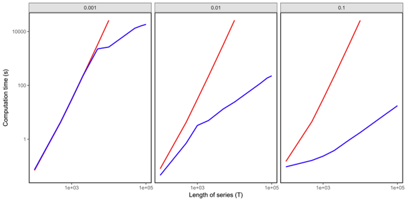
Timing results for solving (5) for the global optimum, using Algorithms 1 ( ) and 2 (
 ). The x-axis displays the length of the time series (T), and the y-axis displays the average running time in seconds. Each panel, from left to right, corresponds to data simulated according to (1) with st ~i.i.d. Poisson(θ), with θ ∈ {0.001, 0.01, 0.1}. Standard errors are on average < 0.1% of the mean compute time. Additional details are provided in
Section 2.4.
). The x-axis displays the length of the time series (T), and the y-axis displays the average running time in seconds. Each panel, from left to right, corresponds to data simulated according to (1) with st ~i.i.d. Poisson(θ), with θ ∈ {0.001, 0.01, 0.1}. Standard errors are on average < 0.1% of the mean compute time. Additional details are provided in
Section 2.4.
We note here that Algorithm 2 for solving (5) is much slower than the algorithm of Friedrich, Zhou and Paninski (2017) for solving (3), which is implemented in Cython and has approximately linear running time. It should be possible to develop a faster algorithm for solving (5) using ideas from Johnson (2013), Maidstone et al. (2017) and Hocking et al. (2017). Furthermore, a much faster implementation of Algorithm 2 would be possible using a language other than R. We leave such improvements to future work.
Algorithm 2:
An algorithm for solving (5) in substantially fewer than operations
 |
3. Simulation study.
3.1. Comparison methods.
In this section, we use in silico data to demonstrate the performance advantages of the ℓ0 approach (5) over two competing approaches:
The ℓ1 proposal (3) of Friedrich and Paninski (2016) and Friedrich, Zhou and Paninski (2017), which involves a single tuning parameter λ.
- A thresholded version of the ℓ1 estimator. Letting denote the solution to (3), we define the post-thresholding estimator as
for L a positive constant. In other words the post-thresholding estimator retains only the estimated spikes for which the estimated increase in calcium exceeds a threshold L. The post-thresholding estimator involves two tuning parameters—λ in (3), as well as the value of L used to perform thresholding.(9)
The post-thresholding estimator is motivated by the fact that the solution to (3) tends to yield many “small” spikes, that is, is near zero, but not exactly equal to zero, for many timesteps. In fact this can be seen in Figure 1(c). As seen in Figure 1(e), the post-thresholding estimator has the potential to improve the performance of the ℓ1 estimator by removing some of these small spikes. Of course, the post-thresholding estimator with L = 0 is identical to the ℓ1 estimator from (3).
3.2. Performance measures.
We measure performance of each method based on two criteria: (i) error in calcium estimation and (ii) error in spike detection.
We consider the mean of squared differences between the true calcium concentration in (1) and the estimated calcium concentration that solves (5),
| (10) |
This quantity involves the unobserved calcium concentrations, c1, …, cT, and thus can only be computed on simulated data. Furthermore, this quantity can be computed for our ℓ0 proposal (5) and for the ℓ1 proposal (3) but not for the postthresholding estimator (9), since the post-thresholding estimator does not lead to an estimate of the underlying calcium concentrations.
We now consider the task of quantifying the error in spike detection. We make use of the Victor–Purpura distance metric [Victor and Purpura (1996, 1997)], which defines the distance between two spike trains as the minimum cost of transforming one spike train to the other through spike insertion, deletion or translation. We also use the van Rossum distance [van Rossum (2001)], defined as the mean squared difference between two spike trains that have been convolved with an exponential kernel with timescale τ = 2.
3.3. Results.
We generated 100 simulated datasets according to (1) with parameter settings γ = 0.96, T = 5000, σ = 0.15 and st ~i.i.d. Poisson(0.01).
On each simulated dataset we solved (5) and (3) for a range of values of the tuning parameter λ. Moreover, we post-thresholded the ℓ1 solution, as in (9), with five different threshold values: L ∈ {0, 0.125, 0.250, 0.375, 0.500}.
Figure 3(a) displays the error in spike event detection for the van Rossum distance, Figure 3(b) displays the error in spike event detection for the Victor–Purpura distance metric and Figure 3(c) displays the error in calcium estimation (10), for the ℓ0 problem (5) and the ℓ1 problem (3), for a range of values of λ. Results are averaged over the 50 simulated datasets.
Fig. 3.
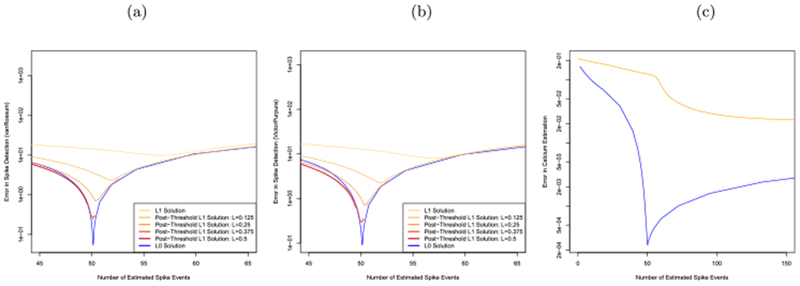
Simulation study to assess the error in spike detection and calcium estimation, for the ℓ1 (3), post-thresholded ℓ1 (9) and ℓ0 (4) problems. (a): Error in spike detection measured using van Rossum distance. (b): Error in spike detection, measured using Victor-Purpura distance. (c): Error in calcium estimation (10). Simulation details are provided in Section 3.
As mentioned earlier, since the calcium concentration is not defined for the post-thresholding estimator (9), the post-thresholding estimator is not displayed in Figure 3(c). In Figures 3(a) and 3(b), five distinct curves are displayed for the post-thresholding operator; each corresponds to a distinct value of L. Note that as L increases, the maximum possible number of estimated spikes from the postthresholding estimator decreases. For example, with λ = 0 and L = 0.5, no more than approximately 50 spikes are estimated by the post-thresholding estimator. For this reason some of the curves corresponding to the post-thresholding estimator appear truncated in Figures 3(a) and 3(b).
Figure 3 reveals that the ℓ0 estimator (5) results in dramatically lower errors in both calcium estimation and spike detection than the ℓ1 estimator (3) (which is equivalent to the post-thresholding operator with L = 0). Although postthresholding with L > 0 improves upon the unthresholded ℓ1 estimator, the ℓ0 estimator still substantially outperforms all competitors in Figures 3(a) and 3(b). Moreover, the ℓ0 estimator requires just a single tuning parameter λ in (5), whereas the post-thresholding procedure involves two tuning parameters, λ in (3) and L in (9), leading to challenges in tuning parameter selection.
Furthermore, the ℓ0 problem (5) achieves the lowest errors in both calcium estimation and spike detection when applied using a value of the tuning parameter λ that yields approximately 50 estimated spikes, which is the expected number of spikes in this simulation. This suggests that it should be possible to use a crossvalidation scheme to select the tuning parameter λ for the ℓ0 approach; we propose such a scheme in Appendix B. By contrast in Figure 3(b), the ℓ1 approach achieves its lowest error in calcium estimation when far more than 50 spikes are estimated. This is a consequence of the fact that the ℓ1 penalty simultaneously reduces the number of estimated spikes and shrinks the estimated calcium. Therefore, the value of the tuning parameter λ in (3) that yields the most accurate estimate of calcium will result in severe over-estimation of the number of spikes. This means that the cross-validation scheme detailed in Appendix B will not perform well for the ℓ1 approach.
4. Application to calcium imaging data.
In this section we apply our ℓ0 proposal (5) and the ℓ1 proposal of Friedrich and Paninski (2016) and Friedrich, Zhou and Paninski (2017) (3), both with and without post-thresholding (9) to two calcium imaging datasets. In the first dataset, the true spike times are known [Chen et al. (2013), GENIE Project (2015)], and so we can directly assess the spike detection accuracy of each proposal. In the second dataset the true spike times are unknown [Allen Institute for Brain Science (2016), Hawrylycz et al. (2016)]; nonetheless, we are able to make a qualitative comparison of the results of the ℓ1 and ℓ0 proposals.
4.1. Application to Chen et al. (2013) data.
We first consider a dataset that consists of simultaneous calcium imaging and electrophysiological measurements [Chen et al. (2013), GENIE Project (2015)], obtained from the Collaborative Research in Computational Neuroscience portal (http://crcns.org/data-sets/methods/cai-1/about-cai-1). In what follows we refer to the spike times inferred from the electrophysiological measurements as the “true” spikes.
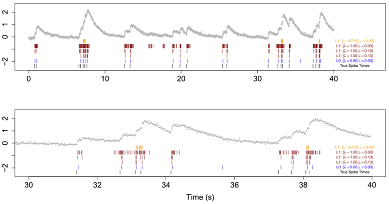
The top panel of Figure 4 shows a 40-second recording from cell 2002, which expresses GCaMP6s. The data are measured at 60 Hz for a total of 2400 timesteps. The raw fluorescence traces are DF/F transformed with a 20% percentile filter as in Figure 3 of Friedrich, Zhou and Paninski (2017). In this 40-second recording there are a total of 23 true spikes; therefore, we solved the ℓ0 and ℓ1 problems with γ = 0.9864405 using values of λ in (5) and (3) that yield 23 estimated spikes. Additionally, we solved the ℓ1 problem with λ = 1 and post-thresholded it according to (9) using L = 0, 0.1, and 0.13; these threshold values yielded 230, 54, and 23 estimated spikes, respectively.
Fig. 4.
Spike detection for cell 2002 of the
Chen et al. (2013)
data. The observed fluorescence ( ) and true spikes (
 ) are displayed. Estimated spike times from the ℓ0
problem (4) are shown in (
) are displayed. Estimated spike times from the ℓ0
problem (4) are shown in ( ), estimated spike times from the ℓ1
problem (3) are shown in (
), estimated spike times from the ℓ1
problem (3) are shown in ( ), and estimated spike times from the post-thresholding estimator (9) are shown in (
 ). Times 0s–35s are shown in the top row; the second row zooms into time 30s–40s in order to illustrate the behavior around a large increase in calcium concentration.
Figure 4 displays the estimated spikes resulting from the ℓ0 proposal, the estimated spikes resulting from the ℓ1 proposal, the estimated spikes from postthresholding the ℓ1 solutions, and the ground truth spikes. We see that the ℓ0 proposal has one false negative (i.e., it misses one true spike at around 7 seconds) and one false positive (i.e., it estimates a spike at around 36 seconds, where there is no true spike). By contrast, the ℓ1 problem concentrates the 23 estimated spikes at three points in time, and therefore suffers from a substantial number of false positives as well as false negatives. Because the ℓ1 penalty controls both the number of spikes and the estimated calcium, the ℓ1 problem tends to put a large number of spikes in a row, each of which is associated with a very modest increase in calcium. This is consistent with the results seen in Figures 1 and 3. Post-thresholding the ℓ1 estimator does lead to an improvement in results relative to the unthresholded ℓ1 method; however, the post-thresholded solution with 23 spikes still tends to estimate a number of spikes in short succession when in fact only one true spike is present, and also misses several true spike events.
We note that the ℓ0 method tends to estimate spike times one or two timesteps ahead of the true spike times. This is due to model misspecification. Model (1) with p = 1 assumes that the calcium concentration increases instantaneously due to a spike event and subsequently decays; however, we see from Figure 4 that in reality, a spike event is followed by an increase in calcium over the course of a few timesteps before the onset of exponential decay. We see two possible avenues to address this relatively minor issue: estimated spike times from the ℓ0 method can be adjusted to account for this empirical observation; or else the optimization problem (5) can be adjusted in order to allow for more realistic calcium dynamics [e.g., by solving an ℓ0 optimization problem corresponding to (1) with p > 1]. We explore the second alternative in Section 5.
In Appendix C we apply an approach proposed by Friedrich, Zhou and Paninski (2017) to approximate the solution to a nonconvex problem using a greedy algorithm. This alternative approach performs quite a bit better than solving the ℓ1 problem (3); however, it does not achieve the global optimum.
4.2. Application to Allen brain observatory data.
We now consider a dataset from the Allen Brain Observatory, a large open-source repository of calcium imaging data from the mouse visual cortex [Allen Institute for Brain Science (2016), Hawrylycz et al. (2016)]. For this data the true spike times are not available, and so it is difficult to objectively assess the performances of the ℓ1, post-thresholded ℓ1, and ℓ0 methods. Instead, for each method we present several fits that differ in the number of detected spikes. We argue that the ℓ0 problem yields results that are qualitatively superior to those of the competitors, in the sense that they are better supported by visual inspection of the data.
For the second ROI in NWB 510221121, we applied the ℓ1, post-thresholded ℓ1, and ℓ0 methods to the first 10,000 timesteps of the DF/F-transformed fluorescence traces. Since the data are measured at 30 Hz, this amounts to the first 333 seconds of the recording. Figure 5 shows the results obtained with γ = 0.981756.
Fig. 5.
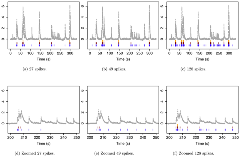
The first 10,000 timesteps from the second ROI in NWB 510221121 from the Allen Brain Observatory. Each panel displays the DF/F-transformed fluorescence ( ), the estimated spikes from the ℓ0
problem (
), the estimated spikes from the ℓ0
problem ( ) (5), the estimated spikes from the ℓ1
problem (
) (5), the estimated spikes from the ℓ1
problem ( ) (3), and the estimated spikes from post-thresholding the ℓ1
problem (
) (3), and the estimated spikes from post-thresholding the ℓ1
problem ( ) (9). The panels display results from applying the ℓ1
and ℓ0
methods with tuning parameter λ chosen to yield (a): 27 spikes for each method; (b): 49 spikes for each method; and (c): 128 spikes for each method. The post-thresholding estimator was obtained by applying the ℓ1
method with λ = 1, and thresholding the result to obtain 27, 49 or 128 spikes. (d)–(f): As in (a)–(c), but zoomed in on 200–250 seconds.
) (9). The panels display results from applying the ℓ1
and ℓ0
methods with tuning parameter λ chosen to yield (a): 27 spikes for each method; (b): 49 spikes for each method; and (c): 128 spikes for each method. The post-thresholding estimator was obtained by applying the ℓ1
method with λ = 1, and thresholding the result to obtain 27, 49 or 128 spikes. (d)–(f): As in (a)–(c), but zoomed in on 200–250 seconds.
For the ℓ0 and ℓ1 estimators we chose the values of λ in (3) and (5) in order to obtain 27, 49 and 128 estimated spikes. For the post-thresholded estimator (9) we set λ = 1, and then selected L to yield 27, 49 and 128 estimated spikes.
As in the previous subsection we see that, when faced with a large increase in fluorescence, the ℓ1 problem tends to estimate a very large number of spikes in quick succession. For example, when 27 spikes are estimated, the ℓ1 problem concentrates the estimated spikes at three points in time [Figure 5(a)]. Even when 128 spikes are estimated, the ℓ1 problem still seems to miss all but the largest peaks in the fluorescence data [Figure 5(c)]. Post-thresholding the ℓ1 estimator improves upon this issue somewhat, but spikes corresponding to smaller increases in fluorescence are still missed; this issue can be clearly seen in Figures 5(d)–(f), which zoom in on a smaller time window.
By contrast the ℓ0 problem can assign an arbitrarily large increase in calcium to a single spike event. Therefore, it seems to capture most of the visible peaks in the fluorescence data when 49 spikes are estimated [Figures 5(b) and 5(e)], and it captures all of them when 128 spikes are estimated [Figures 5(c) and 5(f)].
Though the true spike times are unknown for this data, based on visual inspection, the results for the ℓ0 proposal seem superior to those of the ℓ1 and post-thresholded ℓ1 proposals.
5. Extensions.
We now present two straightforward extensions to the optimization problem (5) for which computationally attractive algorithms along the lines of the one proposed in Section 2 are available.
5.1. Estimation of the intercept in (1).
The model for calcium dynamics considered in this paper (1) allows for an intercept term, β0. In order to arrive at (5) we assumed that the intercept was known and (without loss of generality) equal to zero. However, in practice we might want to fit the model (1) without knowing the value of the intercept β0. In fact, in many settings this may be of great practical importance, since the meaning of the model (1) (and, for instance, the rate of exponential decay γ) is inextricably tied to the value of the intercept.
We now propose a modification to the ℓ0 optimization problem (5) that allows for estimation of the intercept β0. So that the resulting problem can be efficiently solved using the ideas laid out in Section 2, we must ensure that given the estimated spike times, the calcium can be estimated separately between each pair of consecutive spikes. Consequently, we must allow for a separate intercept term between each pair of consecutive spikes. This suggests the optimization problem
| (11) |
where the indicator variable 1(A,B) equals one if the event A ∪ B holds, and equals zero otherwise. Therefore, 1(ct≠γct−1, β0t≠β0,t−1) equals one if the calcium concentration stops decaying or if the intercept changes. Note that in the solution to (11), the intercept is constant between adjacent timesteps, unless there is a spike.
Problem (11) can be recast as a changepoint problem of the form (6) with
Given can be updated in constant time. Thus, the algorithms introduced in Section 2 can be easily modified in order to solve (11) for the global optimum.
5.2. An autoregressive model with p > 1 in (1).
The model (1) allows for the calcium dynamics to follow a pth order autoregressive process. For simplicity this paper focused on the case of p = 1. We now consider developing an ℓ0 optimization problem for the model (1) with p > 1.
It is natural to consider the ℓ0 optimization problem
| (12) |
However, (12) cannot be expressed in the form (6). The penalty in (12) induces a dependency in the calcium that spans more than two timesteps, so that the calcium at a given timestep may depend on the calcium prior to the most recent spike. As a result (12) is computationally intractable.
Instead, we consider a changepoint detection problem of the form (6) with cost function
Thus, the calcium follows a pth order autoregressive model between any pair of spikes; furthermore, once a spike occurs, the calcium concentrations are reset completely. That is, the calcium after a spike is not a function of the calcium before a spike. Consequently, it is straightforward to develop a fast algorithm for solving this changepoint detection problem for the global optimum using ideas detailed in Section 2.
In particular a popular model for calcium dynamics assumes that, between any pair of spikes, the calcium can be well approximated by the difference between two exponentially-decaying functions [Brunel and Wang (2003), Cavallari, Panzeri and Mazzoni (2016), Mazzoni et al. (2008), Volgushev, Ilin and Stevenson (2015)]. This would perhaps be a better model for the data from the Allen Brain Observatory, in which increases in fluorescence due to a spike occur over the course of a few timesteps rather than instantaneously; see Figure 5. This “difference of exponentials” model falls directly within the framework of (1) with p = 2, and hence could be handled handled using the changepoint detection problem just described.
6. Discussion.
In this paper, we considered solving the seemingly intractable ℓ0 optimization problem (5) corresponding to the model (1). By recasting (5) as a changepoint detection problem, we were able to derive an algorithm to solve (5) for the global optimum in expected linear time. It should be possible to develop an even more efficient algorithm for solving (5) that exploits recent algorithmic developments for changepoint detection [Johnson (2013), Maidstone et al. (2017), Hocking et al. (2017)]; we leave this as an avenue for future work.
We have shown in this paper that solving the ℓ0 optimization problem (5) leads to more accurate spike event detection than solving the ℓ1 optimization problem (3) proposed by Friedrich, Zhou and Paninski (2017). Indeed, this finding is intuitive: the ℓ1 penalty and positivity constraint in (3) serves as a exponential prior on the increase in calcium at any given time point and thereby effectively limits the amount that calcium can increase in response to a spike event. By contrast the ℓ0 penalty in (5) is completely agnostic to the amount by which a spike event increases the level of calcium. Consequently, it can allow for an arbitrarily large (or small) increase in fluorescence as a result of a spike event.
While approximations to the solution to the ℓ0 problem (5) are possible [de Rooi and Eilers (2011), de Rooi, Ruckebusch and Eilers (2014), Hugelier et al. (2016), Scott and Knott (1974), Olshen et al. (2004), Fryzlewicz (2014), Friedrich, Zhou and Paninski (2017)], there is no guarantee that such approaches will yield an attractive local optimum on a given dataset. In this paper we completely bypass this concern by solving the ℓ0 problem for the global optimum.
In this paper we have focused on the empirical benefits of the ℓ0 problem (5) over the ℓ1 problem (3). However, it is natural to wonder whether these empirical benefits are backed by statistical theory. Conveniently, both the ℓ0 and ℓ1 optimization problems are very closely related to problems that have been well studied in the statistical literature from a theoretical standpoint. In particular, in the special case of γ = 1, the ℓ0 problem (5) was extensively studied in Yao and Au (1989) and Boysen et al. (2009). Furthermore, when γ = 1, the ℓ1 problem (5) is very closely related to the fused lasso optimization problem,
which has also been extremely well studied [Tibshirani et al. (2005), Mammen and van de Geer (1997), Davies and Kovac (2001), Rinaldo (2009), Harchaoui and Lévy-Leduc (2010), Qian and Jia (2012), Rojas and Wahlberg (2014), Lin et al. (2016), Dalalyan, Hebiri and Lederer (2017)]. However, we leave a formal theoretical analysis of the relative merits of (5) and (3), in terms of ℓ2 error bounds and spike recovery properties, to future work.
Our R-language software for our proposal is available on CRAN in the package LZeroSpikeInference. Instructions for running this software in python can be found at https://github.com/jewellsean/LZeroSpikeInference.
Acknowledgments.
We are grateful to three reviewers and an associate editor for helpful comments that improved the quality of this work. We thank Michael Buice and Kyle Lepage at the Allen Institute for Brain Science for conversations that motivated this work. Johannes Friedrich at Columbia University provided assistance in using his software to solve the ℓ1 problem (3).
APPENDIX A: PROOF OF PROPOSITIONS
A.1. Proof of Proposition 1.
The first sentence follows by inspection. To establish the second sentence, we observe that the cost
can be rewritten by direct substitution of the constraint as
This is a least squares problem and is minimized at
which implies that
and furthermore that for a < t ≤ b the fitted values are . Applying this argument to each segment gives the result stated in Proposition 1.
A.2. Proof of Proposition 2.
The first equation follows by expanding the square for the final form of in the proof of Proposition 1. Given we can calculate in constant time by storing and , and updating each of these sums for the new data point yb+1; we use a closed form expression to calculate . With each of these quantities stored, and are updated in constant time.
APPENDIX B: CHOOSING λ AND γ
Recall that in (5), the parameters λ and γ are unknown. The nonnegative parameter λ controls the tradeoff between the number of estimated spike events and the quality of the estimated calcium fit to the observed fluorescence. The parameter γ,0 < γ < 1, controls the rate of exponential decay of the calcium. We consider two approaches for choosing γ and λ.
B.1. Approach 1.
To estimate γ, we manually select a segment ya:b that, based on visual inspection, appears to exhibit exponential decay. We then estimate γ as
This can be done via numerical optimization.
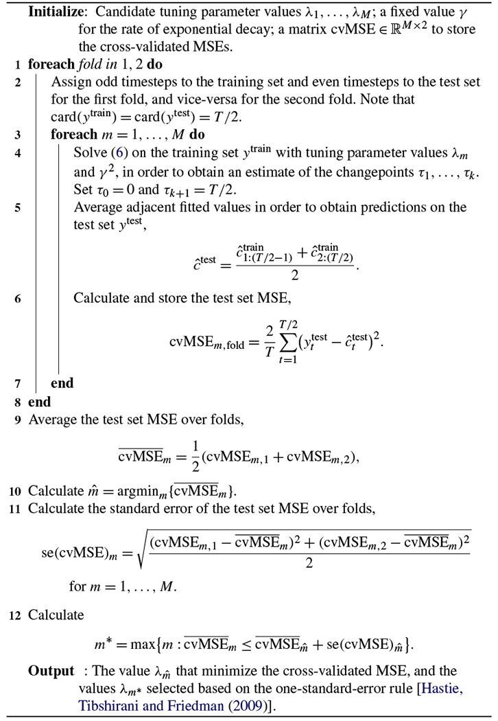
Next, given γ , we select λ via cross-validation. For each value of λ that we consider, we solve (6) on a training set, and then evaluate the mean squared error (MSE) on a hold-out set. Details are provided in Algorithm 3.
B.2. Approach 2.
Pnevmatikakis et al. (2013), Friedrich and Paninski (2016), and Friedrich, Zhou and Paninski (2017) propose to select the exponential decay parameter γ based on the autocovariance function, and to choose the tuning parameter λ such that where the standard deviation σ is estimated through the power spectral density of y, and T is the number of timepoints. We refer the reader to Friedrich, Zhou and Paninski (2017) and Pnevmatikakis et al. (2016) for additional details.
APPENDIX C: A GREEDY APPROACH FOR APPROXIMATING THE SOLUTION TO A NONCONVEX PROBLEM
Friedrich, Zhou and Paninski (2017) consider a variant of the optimization problem (3),
| (13) |
obtained from (3) by setting λ = 0, and changing the convex positivity constraint to the nonconvex constraint that st lies within a nonconvex set. Like (5), (13) is non-convex. Friedrich, Zhou and Paninski (2017) do not attempt to solve (13) for the global optimum; instead, they provide a heuristic modification to their algorithm for solving (5), which is intended to approximate the solution to (13).
Figure 6 illustrates the behavior of this approximate algorithm when applied to the same data as in Figure 4. We set γ = 0.9864405, and considered three values of smin. When smin = 10−8 and smin = 0.1, in panels (a) to (b), too many spikes are estimated. But when smin = 0.3, in panel (c), the solution to (13) is very similar to the solution to (5) with λ = 0.6. Both almost perfectly recover the ground truth spikes. Therefore, in this example, the approximate algorithm of Friedrich, Zhou and Paninski (2017) for solving (13) performs quite well.
Algorithm 3:
A cross-validation scheme for choosing λ (5)
 |
However, (13) is a nonconvex problem, and the approximate algorithm of Friedrich, Zhou and Paninski (2017) is not guaranteed to find the global minimum. In fact, we can see that on the data shown in Figure 6, this approximate algorithm does not find the global optimum. When applied with smin = 0.3, the approximate algorithm yields an objective value of 8.57. By contrast, our algorithm for solving (5) yields a solution that is feasible for (13), and which results in a value of 7.86 for the objective of (13). We emphasize that this is quite remarkable: even though the algorithm proposed in Section 2 solves (5) and not (13), it nonetheless yields a solution that is closer to the global optimum of (13) than does the approximate algorithm of Friedrich, Zhou and Paninski (2017), which is intended to solve (13).
In many cases, the greedy algorithm of Friedrich, Zhou and Paninski (2017) for solving (13) might yield good results that are near the global optimum of (13), and potentially even near the global optimum of (5). However, there is no guarantee that this algorithm will yield a “good” local optimum on any given dataset. By contrast, in this paper we have proposed an elegant and efficient algorithm for exactly solving the ℓ0 problem (5).
Fig. 6.
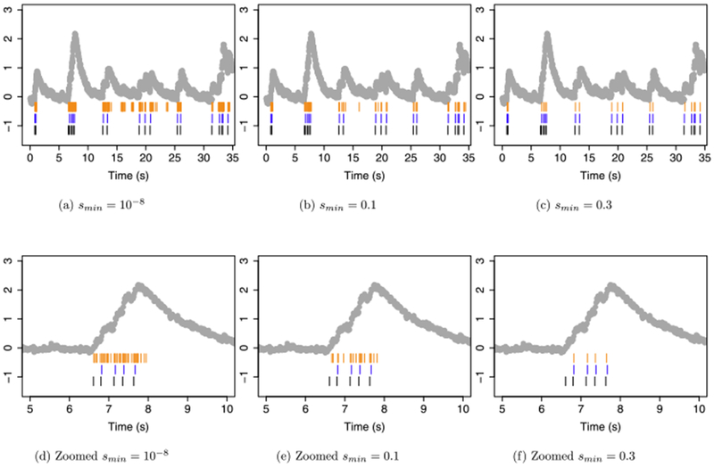
Spike detection for cell 2002 of the
Chen et al. (2013)
data. In each panel, the observed fluorescence ( ) and true spikes (
 ) are displayed. Estimated spikes from problem (13) are shown in (
 ), and the estimated spikes from the ℓ0
problem (5) with λ = 0.6 are shown in (
), and the estimated spikes from the ℓ0
problem (5) with λ = 0.6 are shown in ( ). Times 0 s–35 s are shown in the top row; the second row zooms in on times 5 s–10 s to illustrate behavior around a large increase in calcium concentration. Columns correspond to different values of smin.
Footnotes
Supported by the Natural Sciences and Engineering Research Council of Canada.
Supported in part by NIH Grant DP5OD009145 and NSF CAREER Award DMS-1252624.
Contributor Information
Sean Jewell, Department of Statistics, University of Washington, Seattle, Washington 98195, USA, swjewell@uw.edu.
Daniela Witten, Departments of Statistics and Biostatistics, University of Washington, Seattle, Washington 98195, USA, dwitten@uw.edu.
REFERENCES
- Ahrens MB, Orger MB, Robson DN, Li JM and Keller PJ (2013). Wholebrain functional imaging at cellular resolution using light-sheet microscopy. Nat. Methods 10 413–420. [DOI] [PubMed] [Google Scholar]
- Allen Institute for Brain Science (2016). Stimulus set and response analysis. Technical report, Allen Institute, Seattle, WA. [Google Scholar]
- Aue A and Horváth L (2013). Structural breaks in time series. J. Time Series Anal 34 1–16. MR3008012 [Google Scholar]
- Auger IE and Lawrence CE (1989). Algorithms for the optimal identification of segment neighborhoods. Bull. Math. Biol 51 39–54. MR0978902 [DOI] [PubMed] [Google Scholar]
- Bien J and Witten D (2016). Penalized estimation in complex models In Handbook of Big Data. 285–303. CRC Press, Boca Raton, FL: MR3674823 [Google Scholar]
- Boyd S and Vandenberghe L (2004). Convex Optimization. Cambridge Univ. Press, Cambridge: MR2061575 [Google Scholar]
- Boysen L, Kempe A, Liebscher V, Munk A and Wittich O (2009). Consistencies and rates of convergence of jump-penalized least squares estimators. Ann. Statist 37 157–183. MR2488348 [Google Scholar]
- Braun JV and Müller H-G (1998). Statistical methods for DNA sequence segmentation. Statist. Sci 13 142–162. [Google Scholar]
- Brunel N and Wang X-J (2003). What determines the frequency of fast network oscillations with irregular neural discharges? I. Synaptic dynamics and excitation-inhibition balance. J. Neurophysiol 90 415–430. [DOI] [PubMed] [Google Scholar]
- Cavallari S, Panzeri S and Mazzoni A (2016). Comparison of the dynamics of neural interactions between current-based and conductance-based integrate-and-fire recurrent networks. Frontiers in Neural Circuits 8. [DOI] [PMC free article] [PubMed] [Google Scholar]
- Chen T-W, Wardill TJ, Sun Y, Pulver SR, Renninger SL, Baohan A, Schreiter ER, Kerr RA, Orger MB, Jayaraman V et al. (2013). Ultrasensitive fluorescent proteins for imaging neuronal activity. Nature 499 295–300. [DOI] [PMC free article] [PubMed] [Google Scholar]
- Dalalyan AS, Hebiri M and Lederer J (2017). On the prediction performance of the Lasso. Bernoulli 23 552–581. MR3556784 [Google Scholar]
- Davies PL and Kovac A (2001). Local extremes, runs, strings and multiresolution. Ann. Statist 29 1–65. MR1833958 [Google Scholar]
- Davis RA, Lee TCM and Rodriguez-YAM GA (2006). Structural break estimation for nonstationary time series models. J. Amer. Statist. Assoc 101 223–239. MR2268041 [Google Scholar]
- De Rooi J and Eilers P (2011). Deconvolution of pulse trains with the L0 penalty. Anal. Chim. Acta 705 218–226. [DOI] [PubMed] [Google Scholar]
- De Rooi JJ, Ruckebusch C and Eilers PHC (2014). Sparse deconvolution in one and two dimensions: Applications in endocrinology and single-molecule fluorescence imaging. Anal. Chem 86 6291–6298. [DOI] [PubMed] [Google Scholar]
- Deneux T, Kaszas A, Szalay G, Katona G, Lakner T, Grinvald A, Rózsa B and Vanzetta I (2016). Accurate spike estimation from noisy calcium signals for ultrafast three-dimensional imaging of large neuronal populations in vivo. Nat. Commun 7 12190. [DOI] [PMC free article] [PubMed] [Google Scholar]
- Dombeck DA, Khabbaz AN, Collman F, Adelman TL and Tank DW (2007). Imaging large-scale neural activity with cellular resolution in awake, mobile mice. Neuron 56 43–57. [DOI] [PMC free article] [PubMed] [Google Scholar]
- Friedrich J and Paninski L (2016). Fast active set methods for online spike inference from calcium imaging. In Advances in Neural Information Processing Systems 1984–1992. [Google Scholar]
- Friedrich J, Zhou P and Paninski L (2017). Fast online deconvolution of calcium imaging data. PLoS Comput. Biol 13 e1005423. [DOI] [PMC free article] [PubMed] [Google Scholar]
- Fryzlewicz P (2014).Wild binary segmentation for multiple change-point detection. Ann. Statist 42 2243–2281. MR3269979 [Google Scholar]
- GENIE Project (2015). Simultaneous imaging and loose-seal cell-attached electrical recordings from neurons expressing a variety of genetically encoded calcium indicators. CRCNS.org. [Google Scholar]
- Grewe BF, Langer D,Kasper H,Kampa BM and Helmchen F (2010). High-speed in vivo calcium imaging reveals neuronal network activity with near-millisecond precision. Nat. Methods 7 399–405. [DOI] [PubMed] [Google Scholar]
- Harchaoui Z and Lévy-Leduc C (2010). Multiple change-point estimation with a total variation penalty. J. Amer. Statist. Assoc 105 1480–1493. MR2796565 [Google Scholar]
- Hastie T, Tibshirani R and Friedman J (2009). The Elements of Statistical Learning: Data Mining, Inference, and Prediction, 2nd ed. Springer, New York: MR2722294 [Google Scholar]
- Hastie T, Tibshirani R and Wainwright M (2015). Statistical Learning with Sparsity: The Lasso and Generalizations Monographs on Statistics and Applied Probability 143 CRC Press, Boca Raton, FL: MR3616141 [Google Scholar]
- Hawrylycz M, Anastassiou C, Arkhipov A, Berg J, Buice M, Cain N, Gouwens NW, Gratiy S, Iyer R, Lee JH et al. (2016). Inferring cortical function in the mouse visual system through large-scale systems neuroscience. Proc. Natl. Acad. Sci. USA 113 7337–7344. [DOI] [PMC free article] [PubMed] [Google Scholar]
- Hocking TD, Rigaill G, Fearnhead P and Bourque G (2017). A log-linear time algorithm for constrained changepoint detection. Preprint. Available at ArXiv:1703.03352.
- Holekamp TF, Turaga D and Holy TE (2008). Fast three-dimensional fluorescence imaging of activity in neural populations by objective-coupled planar illumination microscopy. Neuron 57 661–672. [DOI] [PubMed] [Google Scholar]
- Hugelier S, De Rooi JJ, Bernex R, Duwé S, Devos O, Sliwa M, Dedecker P, Eilers PH and Ruckebusch C (2016). Sparse deconvolution of high-density superresolution images. Sci. Rep 6. [DOI] [PMC free article] [PubMed] [Google Scholar]
- Jackson B, Scargle JD, Barnes D, Arabhi S, Alt A, Gioumousis P, Gwin E, Sangtrakulcharoen P, Tan L and Tsai TT (2005). An algorithm for optimal partitioning of data on an interval. IEEE Signal Process. Lett 12 105–108. [Google Scholar]
- Johnson NA (2013). A dynamic programming algorithm for the fused lasso and L0-segmentation. J. Comput. Graph. Statist 22 246–260. MR3173713 [Google Scholar]
- Killick R, Fearnhead P and Eckley IA (2012). Optimal detection of changepoints with a linear computational cost. J. Amer. Statist. Assoc 107 1590–1598. MR3036418 [Google Scholar]
- Lee C-B (1995). Estimating the number of change points in a sequence of independent normal random variables. Statist. Probab. Lett 25 241–248. MR1369518 [Google Scholar]
- Lin K, Sharpnack J, Rinaldo A and Tibshirani RJ (2016). Approximate recovery in changepoint problems, from ℓ2 estimation error rates. Preprint. Available at ArXiv:1606.06746.
- Maidstone R, Hocking T, Rigaill G and Fearnhead P (2017). On optimal multiple changepoint algorithms for large data. Stat. Comput 27 519–533. MR3599687 [DOI] [PMC free article] [PubMed] [Google Scholar]
- Mammen E and Van de Geer S (1997). Locally adaptive regression splines. Ann. Statist 25 387–413. MR1429931 [Google Scholar]
- Mazzoni A, Panzeri S, Logothetis NK and Brunel N (2008). Encoding of naturalistic stimuli by local field potential spectra in networks of excitatory and inhibitory neurons. PLoS Comput. Biol 4 e1000239, 20. MR2476497 [DOI] [PMC free article] [PubMed] [Google Scholar]
- Olshen AB, Venkatraman E, Lucito R and Wigler M (2004). Circular binary segmentation for the analysis of array-based DNA copy number data. Biostatistics 5 557–572. [DOI] [PubMed] [Google Scholar]
- Pnevmatikakis EA,Merel J, Pakman A and Paninski L (2013). Bayesian spike inference from calcium imaging data. In Signals, Systems and Computers, 2013 Asilomar Conference on 349–353. IEEE [Google Scholar]
- Pnevmatikakis EA, Soudry D, Gao Y,Machado TA,Merel J, Pfau D, Reardon T,Mu Y, Lacefield C, Yang W et al. (2016). Simultaneous denoising, deconvolution, and demixing of calcium imaging data. Neuron 89 285–299. [DOI] [PMC free article] [PubMed] [Google Scholar]
- Prevedel R, Yoon Y-G, Hoffmann M, Pak N, Wetzstein G, Kato S, SchröDEL T, Raskar R, Zimmer M, Boyden ES et al. (2014). Simultaneous wholeanimal 3D imaging of neuronal activity using light-field microscopy. Nat. Methods 11 727–730. [DOI] [PMC free article] [PubMed] [Google Scholar]
- Qian J and Jia J (2012). On pattern recovery of the fused lasso. Preprint. Available at ArXiv:1211.5194.
- Rinaldo A (2009). Properties and refinements of the fused lasso. Ann. Statist 37 2922–2952. MR2541451 [Google Scholar]
- Rojas CR and Wahlberg B (2014). On change point detection using the fused lasso method. Preprint. Available at ArXiv:1401.5408.
- Sasaki T, Takahashi N,Matsuki N and Ikegaya Y (2008). Fast and accurate detection of action potentials from somatic calcium fluctuations. J. Neurophysiol 100 1668–1676. [DOI] [PubMed] [Google Scholar]
- Scott AJ and Knott M (1974). A cluster analysis method for grouping means in the analysis of variance. Biometrics 30 507–512. [Google Scholar]
- Theis L, Berens P, Froudarakis E, Reimer J, Rosón MR, Baden T, Euler T, Tolias AS and Bethge M (2016). Benchmarking spike rate inference in population calcium imaging. Neuron 90 471–482. [DOI] [PMC free article] [PubMed] [Google Scholar]
- Tibshirani R, Saunders M, Rosset S, Zhu J and Knight K (2005). Sparsity and smoothness via the fused lasso. J. R. Stat. Soc. Ser. B. Stat. Methodol 67 91–108. MR2136641 [Google Scholar]
- Van Rossum MC (2001). A novel spike distance. Neural Comput 13 751–763. [DOI] [PubMed] [Google Scholar]
- Victor JD and Purpura KP (1996). Nature and precision of temporal coding in visual cortex: A metric-space analysis. J. Neurophysiol 76 1310–1326. [DOI] [PubMed] [Google Scholar]
- Victor JD and Purpura KP (1997). Metric-space analysis of spike trains: Theory, algorithms and application. Network 8 127–164. [Google Scholar]
- Vogelstein JT, Watson BO, Packer AM, Yuste R, Jedynak B and Paninski L (2009). Spike inference from calcium imaging using sequential Monte Carlo methods. Biophys. J 97 636–655. [DOI] [PMC free article] [PubMed] [Google Scholar]
- Vogelstein JT, Packer AM, Machado TA, Sippy T, Babadi B, Yuste R and Paninski L (2010). Fast nonnegative deconvolution for spike train inference from population calcium imaging. J. Neurophysiol 104 3691–3704. [DOI] [PMC free article] [PubMed] [Google Scholar]
- Volgushev M, Ilin V and Stevenson IH (2015). Identifying and tracking simulated synaptic inputs from neuronal firing: Insights from in vitro experiments. PLoS Comput. Biol 11 e1004167. [DOI] [PMC free article] [PubMed] [Google Scholar]
- Yaksi E and Friedrich RW (2006). Reconstruction of firing rate changes across neuronal populations by temporally deconvolved Ca2+ imaging. Nat. Methods 3 377–383. [DOI] [PubMed] [Google Scholar]
- Yao Y-C (1988). Estimating the number of change-points via Schwarz’ criterion. Statist. Probab. Lett 6 181–189. MR0919373 [Google Scholar]
- Yao Y-C and Au ST (1989). Least-squares estimation of a step function. Sankhyā Ser. A 51 370–381. MR1175613 [Google Scholar]
- Zou H (2006). The adaptive lasso and its oracle properties. J. Amer. Statist. Assoc 101 1418–1429. MR2279469 [Google Scholar]