Figure 4.
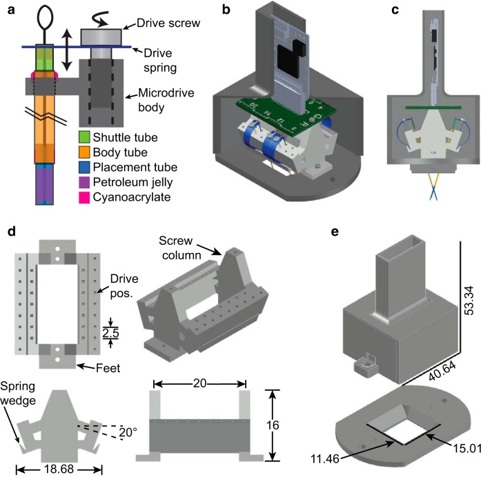
Microdrive system details. a, The FDA is made of a tubing structure that encloses a microwire electrode bundle as it is pushed through the drive axis by a drive spring. The shuttle tube is rigidly attached to a bridge on the head of the drive spring and can move through the body tube. As the drive spring is moved up or down with the turning of a drive screw, the shuttle tube and electrodes move with the spring head. The body tube is fixed to the microdrive body with cyanoacrylate. The body tube is very long, as marked by the black break lines. The placement tube is fixed within the bottom of the body tube. Petroleum jelly space fills the ventral end of the placement tube, except at the electrode tips, to prevent fluids and proteins from entering the drive axis and binding the electrode bundle. b, c, Isometric (b) and side (c) 3D-rendered computer-aided design (CAD) model views of the complete microdrive system to scale. Elements of the system include the following: the microdrive body (light gray structure), drive springs and screws, FDAs, an electrode interface board (green printed circuit board) with a 36-position Omnetics connector, an Intan RHD2216 amplifier, and a headmount (dark gray base and cap). The cap of the headmount has been sliced to view the elements inside. d, Top, front, side, and isometric 3D-rendered CAD model views of the microdrive body. The four primary features on the microdrive body are: the drive positions, the screw columns, the base feet, and the spring wedges. The two drive position arrays have tap holes for 000-120 threads and are angled at 20° with respect to the level screw columns. The 20° provides clearance for the screwdriver when driving and allows the long flexible implants to naturally extend over midline, as depicted in the side view of c. The high-density design has 14 usable drive positions to allow for the targeting of implant sites along an extended rostrocaudal range. Each individual drive position is 2.5 mm in width and includes a drive axis hole for fixing the drive axis bundles to the microdrive body. The two screw columns have 00-90 tap holes and are spaced apart by 20 mm. The feet of the microdrive have 00-90 through-holes and are where the microdrive body is secured to the headmount base. The 1 mm tall spring wedge is on the outside of the drive position arrays and is angled at 20°. The microdrive body is 20 mm in length, 16 mm in height, and 18.68 mm in width. e, Isometric 3D-rendered CAD model views of the headmount. The headmount is composed of two components: the base and the cap. The base has a 4-40 tap hole for the cap screws and a smaller 0.66 mm hole that gets enlarged and tapped with 00-90 threads for the foot screws that secure the microdrive body to the headmount base. The base has a centered 15.01 × 11.46 mm opening for access to the cranium, which allows the placement of multiple guide cannulas and extrasensor modalities. The opening has sloped side and back walls to provide extra room for the maneuverability of forceps when placing the microdrive onto an animal. The 3D CAD models for the Omnetics Nano Strip connector and Intan RHD2216 amplifier were downloaded from the Omnetics (part A79026-001, http://www.omnetics.com/products/neuro-connectors/nano-strip-connectors) and Intan (http://intantech.com/downloads.html) web sites.

