Abstract
The “Kickstand-Rod” technique: new surgical procedure for correction of coronal imbalance (CI) in spinal deformity patients. Coronal plane correction is difficult to achieve and maintain. We developed the technique for CI in deformity patients. The technique is a safe and effective method for correction of CI in deformity patients.
Keywords: Scoliosis, coronal imbalance, kickstand rod technique
Introduction
The burden of adult spinal deformity continues to rise with the aging population. While those with spinal deformity have been shown to suffer from poor quality of life scores, surgery has been shown to be beneficial for these patients (1,2). The importance of coronal balance has been studied, however coronal plane correction can be difficult to achieve and maintain (3-5).
Therefore, we developed the “kickstand rod” technique to address coronal imbalance in adult and pediatric patients. We present a case in which it was successfully used to help correct the coronal plane deformity in an adult patient with combined sagittal and coronal imbalance; at short-term follow-up, the patient has had continued coronal and sagittal plane alignment without associated adverse outcomes.
Technique
In general, our technique involves surgery from an all-posterior approach. The patient is positioned prone and carefully padded in the usual fashion on an Orthopedic Systems Incorporated (OSI) frame with the abdomen and axilla hanging free. Decompressions, facetectomies, and posterior column osteotomies and/or three column osteotomies are performed. Pedicle screws are inserted segmentally and bilaterally; we prefer to use sacral-alar-iliac (S2AI) screws for pelvic instrumentation as well as a transforaminal lumbar interbody fusion at least at L5–S1. We routinely insert three rods across the lumbosacral junction, always inserting the third one after decorticating the underlying bony surfaces and placing the bone graft. The kickstand rod will be inserted on the side towards which the trunk has shifted; on this side, a closed-closed domino should be inserted between two screw heads at the thoracolumbar (TL) junction.
After loosely capturing all the screws into the rods with set caps, the sagittal plane is addressed first in the standard fashion. For example, typical cases of degenerative adult spinal deformity involve compression across the lumbosacral convexity then distraction across this fractional concavity. This helps to lock in lordosis at the lower lumbar segments.
The iliac screw that will serve as the distal fixation point can then be inserted onto the side towards which the trunk has shifted. Dissection with electrocautery is performed about 4–5 cm proximal to the posterior superior iliac spine where the ilium begins to turn horizontally; a Hibbs retractor can help pull the tissue laterally during this dissection. The outer table of the ilium is then partially dissected at this site to help understand the trajectory of the ilium for screw insertion; a large Cobb can then be placed laterally for soft tissue retraction. A pilot hole is placed with the burr at the superior portion of the iliac crest, and then a long gearshift is used to create the pathway down into the ilium distally. It can be swept caudally along the outer table of the pelvis to feel the trajectory of the ilium then inserted into a similar direction into the ilium. A large screw, often 7.5–8.5 mm × 70–80 mm length, can usually be inserted.
Soft tissue is released cephalad to the screw with electrocautery along the path of where the rod will sit, and the kickstand rod is then placed between the TL domino and the kickstand iliac screw; this can also serve as the third or fourth rod of the construct. The rod should be cut slightly long to accommodate the distraction that is placed to lengthen the distance between the iliac wing and the TL junction where the domino is located. The contralateral rod holding the lordosis (e.g., on the lumbosacral convexity) should remain secured while the set caps on the ipsilateral rod (the side of the trunk shift) should be loosened. A rod gripper is then placed proximally on the kickstand rod, and distraction is applied between the rod gripper and the domino proximally with the set plug on the kickstand iliac screw tightened. Distraction can be applied gently multiple times across the domino and across the iliac screws, and the loosened set caps are then tightened to lock the coronal plane correction in place. Care must be taken distally to ensure that the iliac screw does not cut out due to excessive force, especially in osteoporotic bone. In addition, the length of the rod in the ipsilateral S2AI screw needs to be checked to confirm it has not shortened excessively with the lengthening applied by the distraction forces.
Case presentation
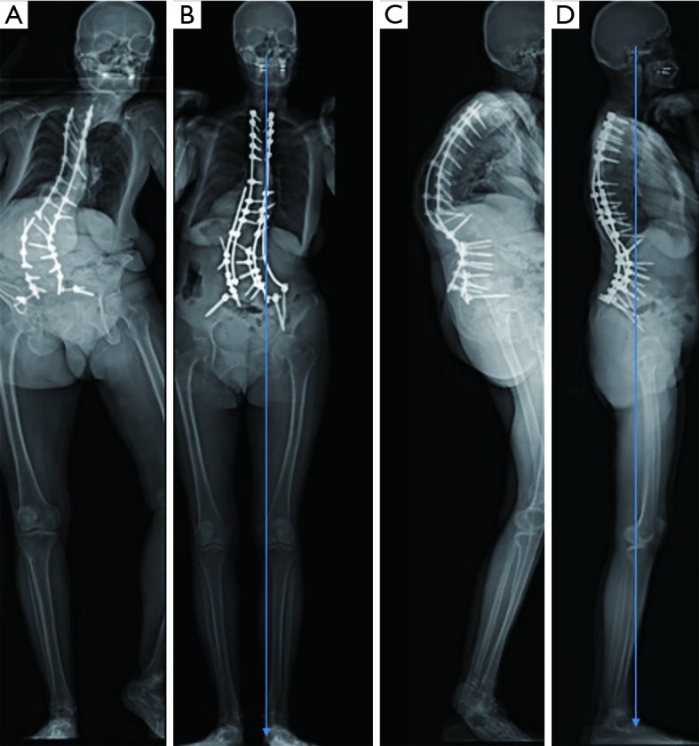
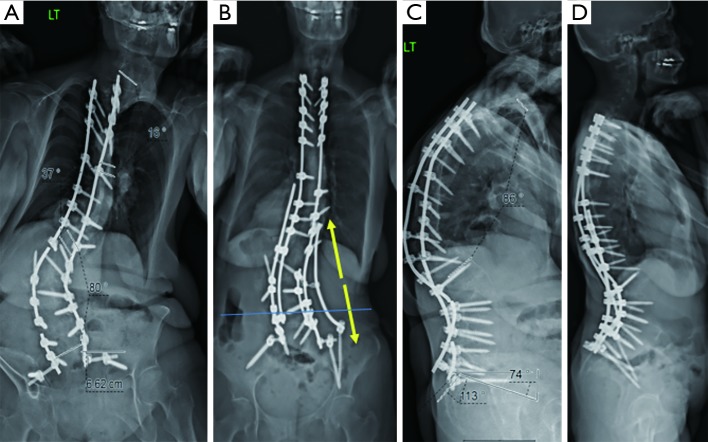
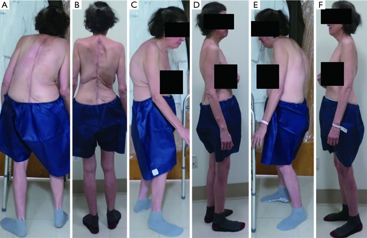
Patient PF is a 62-year-old woman who presented with severe coronal and sagittal imbalance (Figures 1-3). She had undergone a posterior spinal instrumentation and fusion from T3 to the sacrum/ilium and an L2 pedicle subtraction osteotomy (PSO) at a local hospital the year prior; however, she presented to us with progressive kyphoscoliosis, coronal and sagittal plane imbalance, and back pain (Figures 1-3). She reported needing to use a wheelchair outside the house due to her inability to stand upright. On examination, she was leaning forward and pitched to her right, but was overall neurologically intact. She had osteoporosis with a T-score of −3.2. Her images demonstrated broken rods bilaterally, a residual 80-degree coronal plane deformity, and 86 degrees of kyphosis (Figures 1,2). She had +9.2 cm sagittal imbalance and her coronal C7 plumb line fell 8.2 cm to her right. This masked her true coronal imbalance, which was actually much greater; this can be seen on her full body radiographic imaging in which her pelvic obliquity arises from standing with her right heel off the ground. If her feet were both planted on the ground, she was unable to stand without assistance.
Figure 1.
Pre- and postoperative imaging of a 62-year-old woman who presented with severe coronal and sagittal imbalance. (A,C) Preoperative imaging; (B,D) six months postoperative imaging showing correction in the coronal and sagittal planes with implementation of a kickstand rod to provide coronal plane correction (directions in the yellow arrows).
Figure 2.

Pre- and postoperative full-length imaging of the patient from Figure 1. (A,C) Preoperative imaging; (B,D) six months postoperative full-length imaging. Note the right foot being elevated off the ground to help the patient maintain a standing posture in (A), which is corrected on the postoperative imaging in (B).
Figure 3.
Pre- and postoperative clinical photos of the patient before and after correction in the coronal and sagittal planes. (A,C,E) Preoperative clinical photos; (B,D,F) six months postoperative clinical photos.
Given her broken rods and severe coronal and sagittal plane imbalance, she was taken to the operating room (OR) for revision L2 PSO, posterior column osteotomies, revision posterosuperior iliac spine (PSIF) T1-sacrum with pelvic instrumentation, and a kickstand rod construct. A halo was placed for intraoperative traction and positioning, pseudoarthrosis was noted at her prior PSO site, and a solid fusion was confirmed at the other levels. We did posterior column osteotomies through the fusion mass from T3–T5 and T9–L1, and L3–L5. While we traditionally use S2AI screws, we used traditional iliac screws in this case given her prior iliac instrumentation, in which we used her old screw tracts. We upsized these screws and the pedicle screws. Dual headed S1 screws were used, and reduction screws were inserted from L3–L5 bilaterally; all screws were placed freehand, and an intraoperative computed tomography scan was used to confirm position afterward.
We secured two rods on the left side, one from S1 through T12 and the other from the iliac screw to T1. We then attached a domino to T9–T10 on our right rod and cantilevered it across the TL junction. Next, we inserted our kickstand iliac screw on the right side, attached it to a 6.0-mm rod to the domino, and distracted across the domino. We confirmed our alignment with a long anteroposterior (AP) and lateral cassette, completed our decortication and bone grafting, placed a fifth rod from T12–S1 on the right side, and added a crosslink to the kickstand rod for additional stability. The patient is nearly 6-month post-op and has maintained her alignment without complication.
Discussion
In this patient with osteoporosis, significant coronal and sagittal imbalance, and with large forces across her osteotomy sites, the kickstand rod construct helped improve her coronal plane deformity and associated functional pelvic obliquity. This occurred without adverse effect on her sagittal plane, in which her sagittal vertical axis improved from 92 to 13 mm. Her lumbar lordosis also increased from 49 to 69 degrees, which was beneficial in this patient due to her high pelvic incidence and marked preoperative sagittal imbalance.
The decision to implement the kickstand rod technique can be made preoperatively if the patient has significant coronal imbalance, or can be decided intraoperatively after initial instrumentation. Intraoperative decision-making is based on analysis of well-stitched, long cassette coronal radiographs visualizing the entire spine from the base of the skull to the femoral heads. These can be analyzed besides preoperative full-length EOS imaging so that even minor preoperative leg length discrepancy or pelvic obliquity can be accounted for.
The kickstand rod technique is a safe and effective means to improve and maintain coronal balance, as well as provide additional stability, for patients with spinal deformity (6). This technique is suitable for adult and pediatric patients, and for cases where just posterior column or three column osteotomies are used and can be placed at any point in the surgery, including after the construct is in place but persistent coronal imbalance is confirmed.
Acknowledgements
None.
Informed Consent: Written informed consent was obtained from the patient for publication of this manuscript and any accompanying images.
Footnotes
Conflicts of Interest: The authors have no conflicts of interest to declare.
References
- 1.Pellisé F, Vila-Casademunt A, Ferrer M, et al. Impact on health related quality of life of adult spinal deformity (ASD) compared with other chronic conditions. Eur Spine J 2015;24:3-11. 10.1007/s00586-014-3542-1 [DOI] [PubMed] [Google Scholar]
- 2.Riley MS, Bridwell KH, Lenke LG, et al. Health-related quality of life outcomes in complex adult spinal deformity surgery. J Neurosurg Spine 2018;28:194-200. 10.3171/2017.6.SPINE17357 [DOI] [PubMed] [Google Scholar]
- 3.Daubs MD, Lenke LG, Bridwell KH, et al. Does correction of preoperative coronal imbalance make a difference in outcomes of adult patients with deformity? Spine (Phila Pa 1976) 2013;38:476-83. 10.1097/BRS.0b013e3182846eb3 [DOI] [PubMed] [Google Scholar]
- 4.Glassman SD, Berven S, Bridwell K, et al. Correlation of radiographic parameters and clinical symptoms in adult scoliosis. Spine (Phila Pa 1976) 2005;30:682-8. 10.1097/01.brs.0000155425.04536.f7 [DOI] [PubMed] [Google Scholar]
- 5.Ploumis A, Simpson AK, Cha TD, et al. Coronal Spinal Balance in Adult Spine Deformity Patients With Long Spinal Fusions: A Minimum 2- to 5-Year Follow-up Study. J Spinal Disord Tech 2015;28:341-7. 10.1097/BSD.0b013e3182aab2ff [DOI] [PubMed] [Google Scholar]
- 6.Hyun SJ, Lenke LG, Kim YC, et al. Comparison of standard 2-rod constructs to multiple-rod constructs for fixation across 3-column spinal osteotomies. Spine (Phila Pa 1976) 2014;39:1899-904. 10.1097/BRS.0000000000000556 [DOI] [PubMed] [Google Scholar]


