

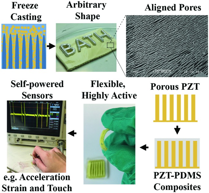
 Self-powered flexible and highly active piezoelectric composite sensors that operate in various sensing modes are manufactured using freeze casting.
Abstract
Self-powered flexible electronics are of particular interest and important for next generation electronics due to their light weight, flexible and self-sustainable properties. Many self-powered sensors made from piezoelectric composite materials are either inflexible or possess low piezoelectricity. In this work, we demonstrate self-powered flexible and highly active pressure and shear sensors based on freeze casting ceramic–polymer structures. A lamellar lead zirconate titanate (PZT) structure is initially developed via freeze-casting and the piezoelectric composites are formed by impregnating a polydimethylsiloxane (PDMS) matrix into the aligned pore channels. The structured PZT–PDMS composites exhibited a high effective longitudinal piezoelectric coefficient (d33*) of 750 pC N–1, which is higher than that of the monolithic ceramic due to the combination of bending and flexural effects. The use of freeze casting enables the manufacture of complex and arbitrary shaped 3D piezoelectric architectures, along with the unique advantages of low-cost and ease of fabrication. A 14 × 14 mm2 PZT–PDMS pressure sensor was able to bend to a small radius of 8 mm and maintain a high d33. Furthermore, the manufactured self-powered sensors are demonstrated in a range of applications, such as acceleration, strain and touch sensors that use the d33, d31 and d15 coefficients to detect longitudinal, transverse and shear loads. This work expands on the potential applications of freeze casting and provides new opportunities for the manufacture of future electronic sensors.
Broader context
Self-powered electronic devices that utilize energy harvesting technology for scavenging ambient energy are highly desirable for next generation wireless and wearable devices since it enables them to work without an external power source and eliminates the need for replacement and management of batteries. Flexible piezoelectric and piezo-composite materials have been directly used as self-powered sensors, but their poor piezoelectric properties and difficulty in achieving various sensing modes, such as the shear sensing mode, limit their performance and applications. In this work, we develop a flexible and highly active piezoelectric polymer composite material using a freeze casting method. The connected piezoelectric phase in the polymer matrix and the combined effect of compression and flexure allow the composites to achieve a high effective piezoelectric coefficient. The unique structure of the ceramic–polymer composite also allows the self-powered sensor to maintain high activity after bending to a small radius. The freeze casting method allows the production of complex device architectures. Using such piezo-composites, we manufacture self-powered sensors that operate in various sensing modes (d31, d33, and d15) and tested with tire, shaker and light finger tapping. This work further expands on the potential applications of freeze casting and provides new opportunities for the manufacture of future electronics.
1. Introduction
Future portable electronics requires devices that are flexible, lightweight and self-powered. There is increasing interest in a range of sensors based on strain, touch and acceleration; with particular emphasis on self-powered sensors or those that can work in combination with energy harvesters1–3 to provide an alternative to conventional batteries with potential to deliver sustainable energy to supply low power electronic devices using ambient forms of energy.
Piezoelectric materials, such as lead zirconate titanate (PZT)4,5 and lead magnesium niobate-lead titanate (PMN-PT),6 have been directly used as self-powered sensors7–16 to sense strain, force and acceleration. The piezoelectric charge coefficient dij, represents the ability to convert mechanical loads into an electric charge and plays a key role in their sensing and energy harvesting performance. Although bulk piezoelectric ceramics have high piezoelectric performance, they are too brittle to be integrated into the flexible electronics. Piezo-composite materials that contain piezoelectric nano- or micro-scale components that are randomly distributed into a polymer matrix10,17,18 are candidates for flexible energy harvesters and self-powered sensing applications. Composite materials take advantage of the flexibility from the polymer matrix and piezoelectricity from the fillers. However, the use of randomly dispersed ceramic fillers often leads to a lack of connectivity, which gives rise to poor levels of polarisation and piezoelectric activity.19 In addition, the permittivity mismatch between the two phases result in an unfavorable electric field distribution that restricts poling of the composite and further reduces piezoelectric properties. A higher connectivity of the ferroelectric ceramic can be achieved with either conventional mechanical dice and fill,13 the use of sacrificial templates,20 and a dielectrophoresis technique that uses an AC electric field to align the ceramic filler.21 However, processes such as dice and fill can damage the ceramic due to the brittle nature of the materials and it is difficult to create complex shapes and device structures. As a result, new types of composite nanogenerators with nano- and micro-scale fibers or patterned structures for self-powered devices have been explored. These nanogenerators include silver nanowires,14 barium titanate (BaTiO3) nanoparticles,22 BaTiO3 nanofibers15,23 in poly(vinylidenefluoride-co-trifluoroethylene) (PVDF-TrFE), and PMN-PT nanowires in polydimethylsiloxane (PDMS).24 Such nanogenerators exhibit good mechanical flexibility, but their piezoelectric properties are often not reported in the literature and are often relatively low. For example, the d33 of aligned BaTiO3 nanowire is d33 = 43 pm V–1,25 which is less than that of the bulk ceramic, where d33 ∼ 86 pm V–1.26 In such nanogenerators, the strain can be applied to induce buckling to provide increased effective piezoelectric coefficients,15 but a buckling mode is not easily exploited in real applications.
It is well-known that the magnitude of the piezoelectric coefficient of ferroelectric ceramics is usually d15 > d33 > d13.27 In addition, the d15 mode is less susceptible to pyroelectric effects due to temperature changes since the charge generated during vibration is collected by electrodes placed perpendicular to the polarization direction. As a result, any pyroelectric charge induced by a temperature change does not contribute to the signal.28 The d15 mode is therefore of interest for sensing as the d15 shear mode has the potential to be effective when used in sensing and energy harvesting applications.20,29 Self-powered piezoelectric sensors are widely used to sense longitudinal21 (d33-mode) and transverse strains15 (d31-mode); for example recently a flexible three dimensional piezoelectric polymer composite made with a polyurethane foam template was recently reported for a pressure and bending sensor.20 However, there is less work on shear (d15-mode) based force sensors. One challenge is to design and manufacture shear force sensors, as it can require a complex configuration or device structure since the electrodes are applied normal to the direction of polarization.
In this paper we demonstrate the manufacture of flexible and highly active strain, acceleration and shear sensor arrays using aligned PZT–PDMS composite materials. The porous PZT was fabricated using a freeze casting technique and the ceramics were shaped into specific architectures for each sensor application. Freeze casting30 is a cost-effective shaping technique that uses ice as template to create a directional porous structure. Due to the unidirectional freezing of the ice crystal, a porous microstructure with unidirectional channels is created, where the pores are formed as a replica of the ice crystals. For the manufacture of piezoelectric composites, freeze casting has the potential to be an easier and more practical shaping technique to create a continuous organized ceramic structure that is necessary for high piezoelectric activity. The PDMS was impregnated into the aligned pores of the freeze-cast PZT to create the PZT–PDMS composite materials. Due to the unidirectional channels formed by PZT and flexible polymer matrix, the composite structure achieved enhanced piezoelectric properties and was able to maintain performance after bending to small radius. Due to the advantages of high activity, flexible nature and ability to form into device geometries, we developed three self-powered sensors that are potential to sense longitudinal (d33), transverse (d31) and shear (d15) motion.
2. Results and discussion
2.1. Fabrication of the sensor structure
The fabrication processes of the flexible force sensors array are shown in Fig. 1. The PDMS-encapsulated hierarchical PZT structure was fabricated using the freeze casting method. For the first step, Fig. 1a, a master mold was 3D printed and the pattern was then transferred to a flexible PDMS mold by simple casting, see Fig. 1b. The prepared PZT water-based suspension was poured into the patterned PDMS mold, Fig. 1c and d, which was then transported to a conducting cold plate that was placed in a liquid nitrogen container for freezing. Fig. 1e–g shows the freeze-casting process inside of the PDMS mold, which is frozen from the base of the mold. Under super-cooled conditions (Fig. 1f), lamellar ice crystals begin to grow upwards and at equilibrium ice crystals push the PZT particles aside. The PZT particles then accumulate between growing ice crystals and consequently form a lamellar structure. When solidification is complete, as in Fig. 1g, the templated PZT-ice sample is demolded and freeze-dried to sublimate the ice, Fig. 1h. In order to densify the structured material and gain appropriate mechanical strength, the hierarchical porous PZT structures are then sintered. After firing process the samples were corona poled and electrodes were formed with silver conductive paint (RS Pro 186-3593). Finally the unidirectional channels in PZT ceramics are filled with a thin layer of PDMS and solidified.
Fig. 1. Schematic of the fabrication process to form a freeze cast sensor array. (a) Design and fabrication of a master mold by additive manufacture. (b) Transfer of 3D pattern to a PDMS mold. (c and d) Fill the PDMS mold with prepared PZT water-based suspension. (e–h) Application of the freeze-casting process. (i) Encapsulate the patterned porous PZT sample in a PDMS matrix.

As described in the introduction, one advantage of the freeze casting method is that it enables the production of the desired arbitrary 3D architecture with simple and low-cost processes, since the geometry of the master mold can be readily altered. The size of the patterns and devices can also be modified by simply changing the design of the PDMS mold. Fig. 2 demonstrates four geometric configurations of porous PZT ceramics formed using PDMS molds; these include cubes, cylinders, rectangular elements, and an arbitrary architecture as shown in Fig. 2a–d respectively.
Fig. 2. Characteristics of the porous PZT and PZT–PDMS composites manufactured by freeze casting. (a–d) Images of freeze cast porous PZT ceramics with different geometric patterns before sintering, e.g. square, round, rectangular, arbitrary showing the capability of producing arbitrary structures. (e) SEM image of a porous PZT ceramic with porosity of 50 vol%, which shows highly aligned unidirectional lamellar microstructure. (f) SEM cross section of the porous PZT structure that shows both dense, cellular zones and lamellar regions. (g) Flexible PZT sensor encapsulated in PDMS. (h) Flexible pressure sensor with painted silver electrodes encapsulated in PDMS. (i and j) SEM image of lamellar PZT structure without and with PDMS, respectively.

2.2. Morphology
In this work, freeze-cast porous PZT ceramics with a porosity level of 50 vol% was studied due to their high figure of merit for sensing31 and harvesting,32 along with appropriate mechanical strength. Fig. 2e shows a scanning electron microscopy (SEM) image of the lamellar microstructure of the sintered porous PZT. The SEM reveals highly aligned unidirectional channels with long range order on the bottom surface of the sintered PZT. Fig. 2f shows the cross section of one pillar in the PZT-air composites of Fig. 2c. The upper ∼100 μm is dense and consists of a cellular zone that was formed at the beginning of the freeze casting cycle in PDMS mold33 since this is in contact with the cold face; and on the dense surface a thin layer of silver electrode has been applied. Ceramic materials are inherently brittle, whether in dense or porous form. Therefore, in this work we have impregnated PDMS into the aligned pores in order to introduce flexibility to the ceramic. Due to the low surface energy of 25 mN m–1,34 the uncured PDMS is able to readily infiltrate and fill the micron-size channels to form the PZT–PDMS composites. This PZT–PDMS composite exhibits moderate flexibility, which is not possible with dense or porous PZT of the same thickness, see Fig. 2g. A final electroded and poled PZT–PDMS pressure sensor made of this PZT–PDMS composite is shown in Fig. 2h showing the individual electrodes on the upper faces of the pillars, with a common electrode at the base of the sensor. Fig. 2i and j shows the freeze cast PZT before and after filling with PDMS, where in Fig. 2j it can be seen that PDMS fills the pore space in the lamellar PZT structure.
2.3. Piezoelectric properties of the composites
The longitudinal d33 piezoelectric coefficient is a parameter that determines device performance for sensing and harvesting. The monolithic and dense PZT materials has a control reference of d33 ∼ 670 pC N–1. In this work, the d33 of freeze casting PZT–air composites with 50 vol% air is 440 pC N–1. In our previous study, it has been explained that the introduction of the porosity reduces the fraction of active material compared to dense PZT, which results in a lower polarization.32 However, after filling the unidirectional channels with PDMS polymer, the d33 increases from 440 pC N–1 to 750 pC N–1. This 70% enhancement is assumed to be a result of flexure due to the elastomer and device architecture, which provides a high effective piezoelectric coefficient (termed a d33*).
In order to understand the mechanism of the enhancement, the polarization-electric field response of the freeze cast PZT–air and PZT–PDMS composites were investigated. Fig. 3 shows the polarisation–electric field (P–E) hysteresis loops of the freeze cast PZT–air and PZT–PDMS composites with maximum electric field of 13 kV cm–1; higher electric fields could not be applied due to the dielectric breakdown. The minimum thickness between top and bottom electrodes is 1 mm. The remnant polarization (Pr) decreased from 3.4 μC cm–2 to 2.3 μC cm–2 after filling and coercive field decreased from 6.6 kV cm–1 to 6 kV cm–1. This decrease of Pr is due to the active lamellar PZT ceramics being clamped by the PDMS polymer matrix.35 The clamping of the lamellar PZT induces charges on the composite surface, via the d33 effect, that act to reduce the measured polarization. From the decrease in polarization after pore infiltration with PDMS, we can confirm that the enhancement of the effective d33* in PZT–PDMS composites is not due to any increased polarization due to the polymer infiltration; this is expected since PDMS is not a ferroelectric and is simply a dielectric material.36
Fig. 3. Polarisation–electric field (P–E) hysteresis loops of freeze cast lead zirconate titanate (PZT) with and without polydimethylsiloxane (PDMS) polymer matrix.

Therefore, we assume the structure of the PZT–PDMS composites helps to improve the piezoelectric response. The improvement of effective d33 (d33*) is due to two reasons; (i) the increased connectivity of the piezoelectric phase, and (ii) the combined effect of compression and flexure that enhances the effective d33 in the composite when it has been compressed. In the range of 0 to 45% strain, PDMS can be regarded as an linear elastic and incompressible material, whose Poisson's ratio is close to 0.5.37,38 When the composite sensor is pressed vertically in the polarization direction, due to the incompressible property of the PDMS, it tends to expand horizontally. In addition to the compression, this expansion introduces an additional flexural response to the lamellar PZT structures. Therefore, the d33 increases in comparison to the PZT–air composites and dense PZT ceramics, which does not exhibit any flexural component.
2.4. Flexibility of the composite
Flexibility is important property for applications related to portable electronics. The flexibility of sensors has often been carried out with a bend test by placing the sensor on an object of increasing curvature.39–41 In order to demonstrate the flexibility and stability of our sensors, the piezoelectric coefficient d33 of a sensor was measured at relaxed state after attaching the sensor to cylinders with a fixed radius of curvature, e.g. 8, 9.5, 12.5, 16, 20, and 25 mm. Fig. 4a shows a flexible PZT–PDMS sensor tightly wrapped around a cylinder with a radius of 16 mm. Fig. 4b shows the percentage change of d33 after each bending of the device to the different radius of curvatures. It can be seen that d33 does not change until the sensor was attached to a cylinder with radius of 16 mm. The d33 slightly decreased to ∼89% of the original value when attached to 16 mm cylinder and is thought to be due to the presence of cracks in freeze cast PZT structure and silver electrodes as four upper electrodes share one common bottom electrode. As shown in Fig. 2j, the PZT network is totally embedded in PDMS and when the PZT–PDMS composite is subjected to flexure with a small strain, small cracks which close on removal of the mechanical load, which is similar to the metals embedded in PDMS.42 However, when the bending radius was increased to 16 mm, irreversible damage occurs to the PZT networks and silver electrodes, thereby leading to a permanent decrease in the d33. A crack is indicated in Fig. 4a and after this initial drop at a radius of curvature of 16 mm the d33 value stabilizes with subsequent increases in curvature. The result demonstrates that our sensor is highly active with high flexibility and stability compared to traditional piezoelectric composites. The bending-induced crack could be avoided by fabricating thinner substrates or individual bottom electrodes for each sensing element.
Fig. 4. Flexibility of PZT–PDMS composite sensors. (a) Flexible sensor attached to a brass cylinder (radius of the cylinder in picture is 16 mm). (b) Percentage of original d33 after attaching to brass cylinder of increasing curvature.

2.5. Sensor configurations
We now demonstrate self-powered sensors using the high activity PZT–PDMS composites. These sensors are employed for sensing by exploiting different modes, which include longitudinal d33, transverse d31, and shear d15 with purposely tailored geometries formed by freeze casting, as shown in Fig. 5a–c where the poling direction in through thickness in all cases and the electrode position is shown for each case. In the following text, we will demonstrate several applications with these three sensing mode sensors.
Fig. 5. Schematic of the three piezoelectric sensor configurations with three sensing modes, e.g. (a) longitudinal [d33], (b) transverse [d31], and (c) shear [d15]. The freezing direction is parallel to the poling direction so that PZT material is aligned in this direction.

2.6. Strain sensor (d31 mode)
We have used the composite as a d31 sensor to measure the strain of the vehicle wheel and here we replicated tire deformation during operation. In order to achieve accurate surface strains for a given distortion of a section of car tire thread, a dynamic test was carried out as shown in Fig. 6a. A section of standard passenger vehicle tire was fitted to an Instron 1342 with a 100 kN load cell servo-hydraulic test machine and the strain gauge was positioned along the central axis of the tire; as shown in the inset of Fig. 6a. The vehicle tire was tested under a cyclic compression by applying a load at a test frequency of up to 10 Hz. The d31 sensor, as in the inset of Fig. 6b, was attached to the central axis of the tire surface. The details of the measurement can be found in Video 1 (ESI†). Fig. 6b shows the strain measured by micro strain gauge (micro measurement) positioned at the central axis of the tire under cyclic compression of 0–3.5 kN and the open circuit voltage response of the d31 sensor placed at the same position. The measured sensor response corresponds to the strain gauge signal and reaches its maximum at ∼1.2 V which correlates with 250 με.
Fig. 6. d 31 sensor measurement with part of a standard passenger vehicle tire. (a) The testing rig in the Instron dynamic test machine. (b) The strain of the tire side wall due to tire deformation and voltage response of the d31 sensor.

2.7. Pressure (d33 mode) and shear (d15 mode) touch sensors
Pressure (d33 mode) and shear (d15 mode) sensor were developed to detect light finger tapping and finger shearing. Fig. 7a is a schematic of the setup to assess the pressure and shear sensor's response to light finger tapping and shearing. In order to simplify the measurement, each pillar shares a single bottom electrode and the pressure sensor contains of four individual upper electrodes labeled as line 1, 2, 3, and 4, see Fig. 2h. Firstly we demonstrated a light finger tapping test on single sensing line of the d33 sensor. The open circuit voltage was measured using Keithley 6517B electrometer with high input impedance (>200 TΩ) for voltage measurement and <1 fA noise. The electrometer was connected through its analog output to the Agilent DSO-X 2024A oscilloscope. Fig. 7b shows the response of one of the four lines of the d33 pressure sensor and it was able to generate a voltage over 1 V.
Fig. 7. d 33 and d15 sensor array's response to light finger tapping and shearing and the study of sensor sensitivity. (a) Schematic of the finger tapping measurement, (b) d33 mode pressure sensor response with active single sensing line. (c) Schematic of the measurement circuit. (d) Voltage response of the d33 pressure sensor to light finger tapping (a reference voltage signal without touching, voltage response of sensor array 1, 2, 3 with light finger tapping and shearing). (e) Voltage response of d15 shear sensor to light finger shearing.

The ability to form a sensor array is important as it can acquire the force distribution and map the applied force. In order to characterize the response of the d33 and d15-mode sensor array to light finger tapping and shearing, the tapping and shearing test was then performed with d33 and d15 sensor connected to the Arduino Uno development board. In the following experiment, we measured the responses of several sensing lines at the same time. The sensor was placed on desk and four sensing lines were connected to an Arduino UNO microcontroller board. Fig. 7c shows the circuit, where each sensing line was connected to the analog to digital converter (ADC) input and loaded with a 1.8 MΩ resistor. As one electrode was connected to ADC's input and second to common ground, the Arduino is not able to deliver the values of negative readings, thus the voltage responses in Fig. 7d and e are all positive. The sensor response of the d33-mode pressure and d15-mode shear sensor are shown in Fig. 7d and e respectively. For sensors in operation, it is important to have a ‘zero’ reference, hence the response without any finger tapping and shearing is shown in Fig. 7d. It can be noticed that there is small noise (voltage < 20 mV) in the response signal during the tapping, which correspond to our previously shown reference signal. With further software development of sensing application this noise could be removed by extracting its reference signal from the sensors reading.
In addition, we studied the sensitivity of the d33 mode pressure and d15 mode shear sensors by investigating sensor voltage response to different accelerations and force. Sensors were attached to the “L” shape holders made of 0.9 mm thick steel plate with the use of PDMS solution, see Fig. 8a. For the d33 sensor a seismic mass was placed on the top using two zirconia masses with a total weight of 13 gram was placed, similarly at the end of the d15 sensor structure one zirconia bead of a 6 gram mass was placed as a tip mass. On the side of the holder, a reference accelerometer was placed and the sensor electrodes were connected with differential probes to the measuring oscilloscope.
Fig. 8. Sensor sensitivity vs. acceleration/force. (a) Experimental setup of the sensor sensitivity measurement (vertical mount of L holder for shear sensor measurements). (b and c) Voltage response of the d33 sensor and d15 sensor to shaker acceleration (m is the seismic mass attached to the sensor).

Both type of sensors were tested with the acceleration levels from –3 to 3 g (+/– 29.42 m s–2, g = 9.8 m s–2). Measurement results are presented in Fig. 8b and c for longitudinal mode test and shear mode respectively. For the shear mode sensor, the presented readout comes from only one (of four) pillar's, see Fig. 2c, while the response for longitudinal sensor is an output from all four electroded pillars (1, 2, 3 and 4) connected in parallel. Both sensing modes show excellent linearity in the presented measurement range and strong repeatability. In the acceleration region of 0.5–3 g the sensor sensitivity varies from ∼26.7 mV g–1 (445 mV N–1) for a singular shear structure to up to ∼90.2 mV g–1 (694 mV N–1) for the longitudinal sensing mode.
Finally, we demonstrate a real-time sensitive response of the pressure sensor in d33-mode in Video 2 (ESI†). This involved dropping a small mass of 0.1 g, half of a cotton bud, 2 cm above from the pressure sensor which is followed by a light sequence of finger tapings onto the pressure sensor. In the Video 2 (ESI†), the drop of cotton bud with input potential energy of 1.96 × 10⁻⁵ J could generate a voltage of ∼200 mV. In combination with the sensitivity test, the touch test shows the ability of the sensor to detect light levels of excitation and the sensor's capability to distinguish the activated region. This could find a potential application in robotic arms for collision or handling detection. Moreover, as the manufacturing process allows creation of a variety of custom forms and shapes of the sensor it could be easily adjusted to the desired application, for example as a robotic skin with pressure and shear functionality.
3. Conclusions
We have demonstrated novel flexible and highly active self-powered force sensor arrays based on highly active composites of lead zirconate titanate (PZT) and polydimethylsiloxane (PDMS). PZT ceramics with highly aligned pore channels have been prepared by freeze casting water-based PZT suspensions, with porosity levels of 50 vol%. The PZT–PDMS composites possess a high effective piezoelectric coefficient, d33* ∼ 750 pC N–1, which is 110% times higher than dense PZT ceramics. This enhancement is due to the connectivity of active piezoelectric materials, and the combined effect of compression and flexure due to the elastomer. The sensor could be flexed to a radius of 8 mm and while continuing to exhibit high piezoelectric activity. The manufacturing approach is simple, but capable of producing complex device architectures. With these superior properties, sensors operating at different modes, e.g. longitudinal, transverse and shear, were fabricated and tested with tire, shaker and even light finger tapping. These sensors perform actively with high flexibility and stability compared to the traditional piezoelectric composites. These prototype PZT–PDMS sensors could be further reduced in scale by fabricating a master mold using methods such as a high-resolution 3D printer and readily configured to combine d33, d31, and d15 sensing modes into a single multi-axis sensor. This work therefore expands on the potential applications of freeze casting and provides new opportunities for the manufacture of future electronic sensors.
4. Experimental section
4.1. Fabrication
Lead zirconate titanate powder (PZT-NCE55) was commercially available and purchased from Noliac and was used to prepare the water-based suspension. The suspension fabrication processes were introduced in our previous work32 and the suspension was ball-milled for 24 hours in zirconia media to create a homogeneous and fine suspension. The PZT powder was dispersed in deionized water to form a suspension with solid loading level of 40 vol%, with polyvinyl alcohol and polyacrylic acid which served as the binder and dispersant respectively. The freezing rate was approximately 0.01 °C μm–1. The filament used for 3D printing was a common printing material acrylonitrile butadiene styrene. PDMS precursor (Sylgard 184A) and curing agent (Sylgard 184B) were purchased from Dow Corning Corp. The mixing ratio of the precursor and curing agent was 10 : 1. The templated PZT-ice sample was demolded and freeze-dried for 24 hours in a vacuum chamber of a freeze-dryer to sublimate the ice. The porous PZT structures were sintered at 1250 °C for 2 hours and cool down naturally in a furnace. Then PZT was corona poled at 130 °C for 15 min with a DC voltage of 14 kV. The poled PZT ceramics were then painted with silver electrodes and finally encapsulated in PDMS and cured in oven at 80 °C for overnight.
4.2. Characterization
The microstructures of the sintered porous PZT ceramics were characterized with scanning electron microscopy (SEM, JSM6480LV, Tokyo, Japan). The porosity level of composite was derived from density data obtained by the Archimedes’ method. The longitudinal piezoelectric charge coefficient d33 was measured using a Berlincourt Piezometer (PM25, Take Control, UK). Impedance and relative permittivity were measured with Solartron 1260 and 1296 Dielectric Interface. The polarization response of the composite materials was measured with Radiant RT66B-HVi Ferroelectric Test system.
4.3. Measurement
A shaker measurement rig was assembled with signal generator Agilent 33220A, Amplifier (Europower EP 1500) and Electrodynamic shaker BRÜEL & KJÆR LDS 201. The sample holder with tested sample was placed on the top of the shaker and excited in the z-axis with a peak amplitude of up to 3 g at constant frequency of 25 Hz. The longitudinal [d33] sensor was placed horizontally on the shaker thus its excitation was parallel to the poling direction. The shear mode sensor [d15], was mounted vertically on the shaker thus its excitation was orthogonal to the poling direction. The shaker with sample under test was placed in the shielded chamber to reduce the noise level upcoming from the mains power line. An analog accelerometer (Analog Devices ADXL316) embedded with the conditioning circuit to a custom-built PCB (Printed Circuit Board) board was mounted on the sample holder and used for reference. The measurement setup was controlled with the custom designed scripts in Python programming language responsible for control, gathering and storing of the test data to the PC files. Each measurement for a given acceleration level was repeated 10 times, and results presented are the average values from these measurements.
Author contributions
Dr Xie, Mr Kraśny and Prof. Bowen conceived and designed the experiment. Dr Xie designed sensor configurations, fabricated the sensor molds and PZT–PDMS sensors, performed flexibility test, finger tapping experiment and data processing. Dr Zhang fabricated the PZT–PDMS composite and sensors, performed poling and the d33 measurement of PZT–PDMS composite material. Dr Xie and Dr Yan performed microscopy. Mr Kraśny performed shaker experiment and data processing. Dr Khanbareh designed tire experimental setup. Mr Gathercole performed the d31 experiment. Dr Xie and Prof. Bowen contributed to the general idea. Prof. Bowen supervised the work. Dr Xie, Mr Kraśny and Prof. Bowen contributed to the writing of the article. All authors contributed to the discussion of the article.
Conflicts of interest
There are no conflicts to declare.
Supplementary Material
Acknowledgments
Dr M. Xie, Mr M. J. Kraśny, Mr N. Gathercole and Prof. C. R. Bowen, would like to acknowledge the funding from the European Research Council under the European Union's Seventh Framework Programme (FP/2007–2013)/ERC Grant Agreement no. 320963 on Novel Energy Materials, Engineering Science and Integrated Systems (NEMESIS). Dr Y. Zhang would like to acknowledge the European Commission's Marie Skłodowska-Curie Actions (MSCA), through the Marie Skłodowska-Curie Individual Fellowships (IF-EF) (H2020-MSCA-IF-2015-EF-703950-HEAPPs) under Horizon 2020.
Footnotes
†Electronic supplementary information (ESI) available: Videos of the responses of sensors. See DOI: 10.1039/c8ee01551a
References
- Bowen C. R., Kim H. a., Weaver P. M., Dunn S. Energy Environ. Sci. 2014;7:25. [Google Scholar]
- Bowen C. R., Taylor J., LeBoulbar E., Zabek D., Chauhan A., Vaish R. Energy Environ. Sci. 2014;7:3836–3856. [Google Scholar]
- Wang Z. L., Chen J., Lin L. Energy Environ. Sci. 2015;8:2250–2282. [Google Scholar]
- Yang Y., Zhou Y., Wu J. M., Wang Z. L. ACS Nano. 2012;6:8456–8461. doi: 10.1021/nn303414u. [DOI] [PubMed] [Google Scholar]
- Zhang K., Wang S., Yang Y. Adv. Energy Mater. 2017;7:1601852. [Google Scholar]
- Zhang R., Jiang B., Cao W. J. Appl. Phys. 2001;90:3471. [Google Scholar]
- Hwang G. T., Kim Y., Lee J.-H., Oh S., Jeong C. K., Park D. Y., Ryu J., Kwon H., Lee S.-G., Joung B., Kim D., Lee K. J. Energy Environ. Sci. 2015;8:2677–2684. [Google Scholar]
- Hwang G. T., Park H., Lee J. H., Oh S., Il Park K., Byun M., Park H., Ahn G., Jeong C. K., No K., Kwon H., Lee S. G., Joung B., Lee K. J. Adv. Mater. 2014;26:4880–4887. doi: 10.1002/adma.201400562. [DOI] [PubMed] [Google Scholar]
- Il Lee T., Jang W. S., Lee E., Kim Y. S., Wang Z. L., Baik H. K., Myoung J. M. Energy Environ. Sci. 2014;7:3994–3999. [Google Scholar]
- Alluri N. R., Selvarajan S., Chandrasekhar A., Saravanakumar B., Jeong J. H., Kim S. J. Compos. Sci. Technol. 2017;142:65–78. [Google Scholar]
- Mao Y., Zhao P., McConohy G., Yang H., Tong Y., Wang X. Adv. Energy Mater. 2014;4:1301624. [Google Scholar]
- Sharma T., Je S. S., Gill B., Zhang J. X. J. Sens. Actuators, A. 2012;177:87–92. [Google Scholar]
- Safari A., Allahverdi M., Akdogan E. K. J. Mater. Sci. 2006;41:177–198. [Google Scholar]
- Chen H. J., Han S., Liu C., Luo Z., Shieh H. P. D., Hsiao R. S., Yang B. R. Sens. Actuators, A. 2016;245:135–139. [Google Scholar]
- Chen X., Li X., Shao J., An N., Tian H., Wang C., Han T., Wang L., Lu B. Small. 2017;13:1604245. doi: 10.1002/smll.201604245. [DOI] [PubMed] [Google Scholar]
- Lee M., Bae J., Lee J., Lee C.-S., Hong S., Wang Z. L. Energy Environ. Sci. 2011;4:3359. [Google Scholar]
- Lee M., Chen C. Y., Wang S., Cha S. N., Park Y. J., Kim J. M., Chou L. J., Wang Z. L. Adv. Mater. 2012;24:1759–1764. doi: 10.1002/adma.201200150. [DOI] [PubMed] [Google Scholar]
- Il Park K., Lee M., Liu Y., Moon S., Hwang G. T., Zhu G., Kim J. E., Kim S. O., Kim D. K., Wang Z. L., Lee K. J. Adv. Mater. 2012;24:2999–3004. doi: 10.1002/adma.201200105. [DOI] [PubMed] [Google Scholar]
- Newnham R. E., Skinner D. P., Cross L. E. Mater. Res. Bull. 1978;13:525–536. [Google Scholar]
- Zhang G., Zhao P., Zhang X., Han K., Zhao T., Zhang Y., Jeong C. K., Jiang S., Zhang S., Wang Q. Energy Environ. Sci. 2018 doi: 10.1039/C8EE00595H. [DOI] [Google Scholar]
- Deutz D. B., Mascarenhas N. T., Schelen J. B. J., de Leeuw D. M., van der Zwaag S., Groen P. Adv. Funct. Mater. 2017;27:1700728. [Google Scholar]
- Zhao Y., Liao Q., Zhang G., Zhang Z., Liang Q., Liao X., Zhang Y. Nano Energy. 2015;11:719–727. [Google Scholar]
- Song Y., Shen Y., Liu H., Lin Y., Li M., Nan C.-W. J. Mater. Chem. 2012;22:8063. [Google Scholar]
- Xu S., Yeh Y. W., Poirier G., McAlpine M. C., Register R. A., Yao N. Nano Lett. 2013;13:2393–2398. doi: 10.1021/nl400169t. [DOI] [PubMed] [Google Scholar]
- Zhou Z., Tang H., Sodano H. A. ACS Appl. Mater. Interfaces. 2013;5:11894–11899. doi: 10.1021/am403587q. [DOI] [PubMed] [Google Scholar]
- Felten F., Schneider G. A., Saldana J. M., Kalinin S. V., Saldaña J. M., Kalinin S. V. J. Appl. Phys. 2004;96:563–568. [Google Scholar]
- Kanno I., Akama K., Wasa K., Kotera H. Appl. Phys. Express. 2009;2:091402. [Google Scholar]
- Licht T. R., Andersen H., Jensen H. B. Bruel Kjaer Tech. Rev. 1987;2:1–22. [Google Scholar]
- Newnham R. E., Safari A., Giniewicz J., Fox B. H. Ferroelectrics. 1984;60:15–21. [Google Scholar]
- Deville S., Saiz E., Nalla R. K., Tomsia A. P. Science. 2006;311:515–518. doi: 10.1126/science.1120937. [DOI] [PubMed] [Google Scholar]
- Tressler J. F., Alkoy S., Newnham R. E. J. Electroceram. 1998;2:257–272. [Google Scholar]
- Zhang Y., Xie M., Roscow J., Bao Y., Zhou K., Zhang D., Bowen C. R. J. Mater. Chem. A. 2017;5:6569–6580. doi: 10.1039/c7ta00967d. [DOI] [PMC free article] [PubMed] [Google Scholar]
- Zhang Y., Bao Y., Zhang D., Bowen C. R. J. Am. Ceram. Soc. 2015;98:2980–2983. [Google Scholar]
- Fuard D., Tzvetkova-Chevolleau T., Decossas S., Tracqui P., Schiavone P. Microelectron. Eng. 2008;85:1289–1293. [Google Scholar]
- Nelson L. J., Bowen C. R., Stevens R., Cain M. and Stewart M., High-field behavior of piezoelectric fiber composites, 2003, vol. 5053, pp. 5012–5053. [Google Scholar]
- Racles C., Bele A., Dascalu M., Musteata V. E., Varganici C. D., Ionita D., Vlad S., Cazacu M., Dünki S. J., Opris D. M. RSC Adv. 2015;5:58428–58438. [Google Scholar]
- Armani D., Liu C. and Aluru N., in Technical Digest. IEEE International MEMS 99 Conference. Twelfth IEEE International Conference on Micro Electro Mechanical Systems (Cat. No. 99CH36291), 1999, pp. 222–227.
- Inglis D. W. Biomicrofluidics. 2010;4:026504. doi: 10.1063/1.3431715. [DOI] [PMC free article] [PubMed] [Google Scholar]
- Wu X., Ma Y., Zhang G., Chu Y., Du J., Zhang Y., Li Z., Duan Y., Fan Z., Huang J. Adv. Funct. Mater. 2015;25:2138–2146. [Google Scholar]
- Gaikwad A. M., Whiting G. L., Steingart D. A., Arias A. C. Adv. Mater. 2011;23:3251–3255. doi: 10.1002/adma.201100894. [DOI] [PubMed] [Google Scholar]
- Ramuz M., Tee B. C. K., Tok J. B. H., Bao Z. Adv. Mater. 2012;24:3223–3227. doi: 10.1002/adma.201200523. [DOI] [PubMed] [Google Scholar]
- Adrega T., Lacour S. P. J. Micromech. Microeng. 2010;20:055025. [Google Scholar]
Associated Data
This section collects any data citations, data availability statements, or supplementary materials included in this article.