Abstract
Purpose:
Incorporating high dielectric constant (HDC) materials into radiofrequency (RF) coils has been shown to effectively improve RF coil performance at 7 and 3 T because of the induced displacement current in the high dielectric constant materials. The displacement current is proportional to the RF field frequency and permittivity of the material. The aim of this paper is to investigate the effect of high dielectric constant materials with even greater permittivity on the RF field at 1.5 T and 3 T.
Methods:
Several monolithic ceramic materials with an ultra-high dielectric constant ranging from 1200 to 3300 were investigated at 1.5 T and 3 T with phantom and human brain imaging along with computer modeling.
Results:
Experimental measurements in phantom studies showed a significant enhancement of signal-to-noise ratio (50–100%) and strong transmission power reduction (3–27-fold). Under suboptimal experimental conditions in this study, the signal-to-noise ratio in the human brain cortex was nearly doubled, which produced high-resolution image without the associated stronger magnetic susceptibility artifacts and elevated specific absorption rate concerns at higher field strengths.
Conclusions:
Use of ultrahigh dielectric constant ceramic materials is a simple and low-cost approach that could further improve the RF technology to maximize image signal-to-noise ratio and reduce RF energy deposition for human studies.
Keywords: MRI, 1.5T, 3T, SNR, high permittivity, RF field, B1 field, high dielectric constant
INTRODUCTION
It has been demonstrated that incorporating high dielectric constant (HDC) materials with permittivity values between 70 and approximately 500 could effectively alter radiofrequency (RF) field distribution and significantly improve the performance of RF coils. Specifically, HDC materials have been shown to improve transmit efficiency (B+1) (1–3) and receive sensitivity (B−1) (4), leading to a significant increase in image signal-to-noise ratio (SNR) (5,6) and reduction of specific absorption rate (7–9). This effect was introduced using water with a permittivity of approximately 70 at 3 T to redistribute the field in a spiral birdcage coil (10), and body imaging (11). At 7T, this approach was initially proposed as a means for RF field shimming and focusing (12), and subsequently extended to various specific applications (1,13,14). Multiple approaches with higher relative permittivity materials have since been developed for use in passive B1 shimming.
The effect of the HDC material on the RF coil field distribution is based on the theory that the induced displacement current in the HDC materials can act as a secondary RF field source that subsequently enhances the B1 field in the nearby region. The displacement current is proportional to the RF field frequency and permit-tivity of the material. Therefore, a higher permittivity is needed to achieve the same effect in lower static magnetic field applications. Several approaches have been attempted to achieve a higher permittivity with aqueous mixtures of powders (15,16) or beads of dielectric materials (17,18). To achieve an even higher permittivity in composite dielectrics, a transition to high-density monolithic ceramics is necessary. As the maximal density of the ceramic increases in theoretical density from 55% (powder slurry) or 74% (beads) to 96% (19–21), the permittivity values can increase exponentially by factors of 2 to 10 with increasing density. As such, we refer to these monolithic ceramics as ultrahigh dielectric constant (uHDC) materials. Such materials not only have a significantly higher relative permittivity, but also have one to three orders of magnitude lower loss as compared with water-based mixtures. With these novel electric properties, we have demonstrated that uHDC ceramics can produce a greater enhancement of RF field than the water-based materials used previously, particularly for lower static magnetic field applications (22,23). Most recently, applications of the uHDC ceramics to spine imaging at 3T (24) and 31P chemical shift imaging at 7T were also demonstrated (25).
In this research, we further investigated uHDC ceramic materials at 1.5T and 3T with phantom and human brain imaging, along with computer modeling. We demonstrated that uHDC ceramics can alter the RF field distribution and significantly improve the performance of RF coils for 1.5T and 3T proton imaging.
THEORY
The theoretical background of the HDC effect has been discussed in several previous publications (1,2,26). However, it is deemed necessary to consider its physical interpretation in greater detail and describe certain general characteristics that can be used to guide future applications of the HDC effect in RF engineering. The RF magnetic field distribution is generally described primarily by the Maxwell’s equations as follows:
| [1] |
where B1 and E are the magnetic flux density and electric field strength of the RF field, respectively; σ is the electrical conductivity; ɛr is the relative electric permittivity or dielectric constant; and ɛ0 is permittivity of free space. The first term on the right side of Equation [1] (σE) is conductive current density, Jc; and the second term
| [2] |
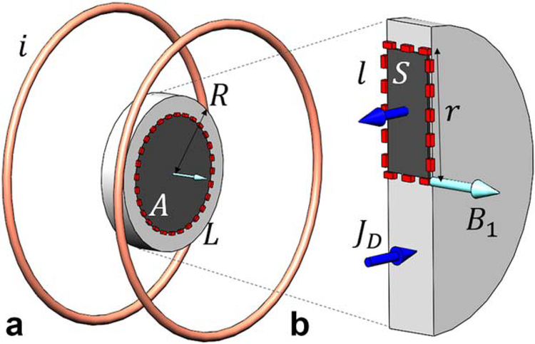
is the displacement current density, Jd. As illustrated in the example in Figure 1, the line integral path, L and 1, on the left sides of the two equations encircle the corresponding area, A and S, of the surface integrals, respectively. These two coupled equations must be solved simultaneously. Equation [1] has been given conventionally in differential form in the previous publications to make a theoretical statement that the displacement current can enhance the RF field locally as a field source in the near-field condition. These two equations are expressed in integral form here for convenience in the following discussions on the near-field behavior of the electromagnetic field. In this case, the electric properties of the sample influence the source field distribution and radiation is ignorable. We assume that the electric properties are regionally uniform within the coil elements, uHDC pads, or tissue sample. In practice, these equations can only be solved numerically because of the complicated geometry of the RF coil-sample configuration.
FIG. 1.
Diagram of the analytical solution and computer modeling of a Helmholtz coil pair with an uHDC disk in between. The magnetic field, B1, is generated by a current, i=1 Am in each loop, with radius 50 mm. a: An uHDC material disk with ɛr =1000 and radius R = 20 mm (small disk) and 40 mm (large disk), respectively, is placed in the center of the coil. For the integration of Equation [2], the line integral along the circular path, L, with radius, r, and the surface integral of enclosed area, A, are performed in the uHDC disk. b: For integration of Equation [1], the line integral along the rectangular path l and enclosed surface integral over S are performed over the uHDC disk cross section. Using the same configuration, computer modeling was also performed.
To illustrate the uHDC effect on the B1 field of the RF coil, it is instructive to use a simplified example such that an analytical solution can be derived approximately under the following assumptions. A disk of uHDC material with radius R is placed into the B1 field of a pair of Helmholtz coils as shown in Figure 1a. The B1 of the coil is uniformly distributed, passing through perpendicularly to the uHDC disk, and given by
| [3] |
where b1 is the magnitude of the B1 field. As indicated in Figure 1a, performing differentiation with respect to t and the line integration on the left side of Equation [2] along the circular path L, where E is a constant and surface integration on the right side of equation over the enclosed area, A, where B1,coil is a constant, yield the induced electric field perpendicular to B1,coil in the uHDC disk, as follows:
| [4] |
The solution in Equation [4] is obtained approximately by considering only the contribution of B1,coil. As such, the E field in the uHDC disk induced by the B1 field of the coil using Faraday’s Law is linearly dependent on ω and radius r of the integral path. Additionally, in this case, E is not conservative, as no electric charge accumulation is formed as a result of the azimuthal symmetry of the uHDC disk with respect to B1,coil.
Subsequently, the line integration along the path 1 and surface integral over the corresponding enclosed area S on each side of Equation [1], as indicated in Figure 1b, can be performed. Assuming that the B1 field inside the uHDC disk is perpendicular to the linear integral path along the radius direction, the B1 field in the uHDC can be expressed as
| [5] |
Because no appreciable current density could be formed at the surface, r = R, where B1(R) ~ B1,coil, then
| [6] |
Equation [6] can be considered as the percent change of B1 induced by the uHDC disk at its center (r = 0).
Several conclusions can be drawn from these results. The first term of Equation [6] represents the contribution of the induced dielectric current (a part of σE) by the uHDC material, which is equivalent to the Eddy current that is linearly dependent on ɷ and 90°delayed in phase with the field produced by the RF coil, canceling the B1,coil. The second term is from the contribution of displacement current, which is quadratically dependent of ɷ and in-phase with respect to B1 of the coil, enhancing B1,coil. As such, with consideration of the continuity property of the B1 across the boundary of uHDC material and sample, the magnetic field flux generated by the displacement current coherently enhances the B1 field of the RF coil in the sample. In contrast, the conductive current in the uHDC would reduce the B1 field and produce dielectric loss and increased thermal noise in the images. Therefore, the conductivity or dielectric loss of uHDC material should be made as low as possible to reduce these detrimental effects of introducing uHDC materials into the RF coils.
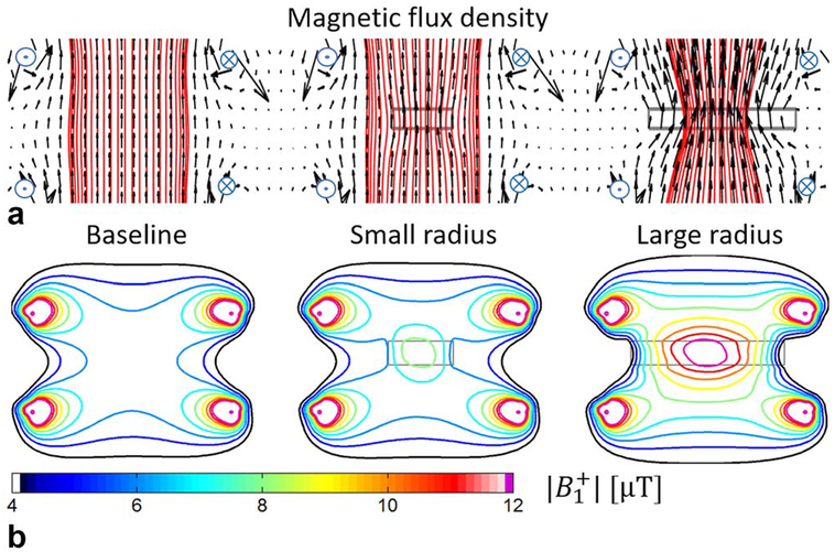
To illustrate the focusing effect of the uHDC disk on the B1 distribution using this example, Figure 2a shows vector plots of the numerically calculated B1 field distributions without and with uHDC disks of two different radii. As indicated, B1,coil flux is “pulled” or “focused” by the uHDC disks; with a larger radius, this effect is stronger as it includes more B1 flux lines generated by the coil. The corresponding contour lines in Figure 2b illustrates this focusing effect more quantitatively. A high B1 field plateau is created in and near the uHDC disks. With a larger radius, this effect becomes larger. The high-field contour lines (magenta, red, and yellow colors) that can be seen only around the areas very close to the current sources also occur in and around the uHDC disks, indicating strong B1 enhancement in these regions.
FIG. 2.
(a) Magnetic flux density plots and (b) contour plots of the calculated B1 field of the Helmholtz coil without (left) and with a small (middle) and a large (right) uHDC disk (as shown in Fig. 1) are presented, respectively. Additionally, a vector plot is overlaid in the flux density map to show the magnitude and directional changes by the uHDC disks. The uHDC disks produce stronger B1 field plateaus near disks by focusing the flux lines of the coil.
Because the contribution of Jd to the B1 of the RF coil is proportional to ɷ2, for applications at lower static field strength such as 1.5 T, the permittivity of the uHDC material must be proportionally higher to those at 3 and 7T to achieve the same or greater effect. In contrast, for a given static field strength, this effect increases linearly with the permittivity of the uHDC blocks.
Several caveats must be considered for the proper use of uHDC materials for RF field engineering. First, the solution of Equation [6] can only be considered as a first-order approximation, because Equations [1] and [2] are coupled, and exact solutions for E and B1 must be solved simultaneously for a given coil-sample configuration. If the RF coil is retuned and matched after the uHDC material is placed into the coil, this assumption should produce a reasonable approximation. Second, the wave behavior is ignored in this discussion. The retardation effect of the RF field, particularly in the uHDC material and sample, could significantly change the B1 field behavior as seen at 7T. For 3T applications, the permittivity of uHDC materials is on the order of thousands, such that the wave behavior and associated self-resonance may occur in the uHDC disk or any other geometric shape of given dimensions. Such materials with given geometry could have certain intrinsic resonance modes (27–29) at the frequency of interest. In this case, the field distribution in the uHDC disk should be theoretically treated and experimentally implemented differently.
METHODS
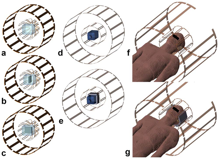
The phantom and brain imaging studies were modeled to demonstrate the effect of the uHDC blocks on the quadrature transmit body coil and the receive array coil as shown in Figure 3. Two experimental phantoms containing water with T1 (1800 ms) and conductivity (σ = 0.6 S/m) matched to average brain tissue properties of the male Virtual Family model Duke (30) at either 1.5 T or 3T were used. To investigate the orientation dependence of the uHDC block with respective to the RF field, B1, Phantom 1 (Figs. 3a–3c) consisted of a container (150 × 150 × 130 mm) with a rectangular uHDC block (100 × 90 × 16 mm) completely submerged in with its largest face either perpendicular (Fig. 3b) or parallel (Fig. 3c) to the direction of the B1 field of the RF coil.
FIG. 3.
Experimental and computer modeling configurations for (a–c) Phantom 1, (d, e) Phantom 2, and (f, g) human studies.
The composition of the uHDC blocks is Lead Zirconate Titanate, Pb(ZrxTi1-x)O3 (PZT) (HyQ Research Solutions, State College, PA), which is at the morphotropic phase boundary (x = 0.5) (31). The ceramic powder was mixed with a binding agent, pressed, and sintered (17,32). Two types of high-permittivity PZT ceramics were tested: a soft PZT that is synthesized with a donor dopant, and a hard PZT that is synthesized with an acceptor dopant. Their respective conductivity and relative permittivity were characterized using the Hakki-Coleman resonator and coaxial reflection methods (33,34). The permittivity of the hard PZT block was 1200 with a loss tangent of 0.04, and the soft PZT block was 3300 with a loss tangent of 0.05. The intrinsic resonance modes for each uHDC block were determined with a network analyzer. No intrinsic resonance modes were found at either 64 or 125 MHz in the two types of uHDC blocks. The lowest resonance mode for permittivities 1200 and 3300 are approximately 120 and 70 MHz, respectively. The corresponding numerical model for Phantom 1 was recreated following its exact geometry, permittivity, and conductivity.
Phantom 2 (Figs. 3d–3e) consisted of a rectangular bottle (100 × 100 × 240 mm) surrounded by one uHDC block on each of the sides on the bottom half of the bottle. Figures 3f and 3g illustrate the male Virtual Family model Duke (30) used in the numerical simulations of in vivo human brain imaging. The RF coils were modeled using geometry and dimensions close to the coil used in the experiment. All of the RF field calculations were performed with xFDTD software (Remcom Inc, State College, PA), and postprocessing of the simulation results was performed with in-house scripts in MATLAB (The MathWorks Inc, Natick, MA).
The transmit field maps (B+1) were generated from a quadrature-driven birdcage volume coil. The receive sensitivity map (B−1) was generated by the sum of squares of B−1 of each individual coil in an eight-channel receive array. The displacement current Jd distribution inside the uHDC materials was also calculated.
All data at 3T were acquired on a Siemens Magnetom TIM Trio system (Siemens Medical, Erlangen, Germany) using an eight-channel head receive array coil (Invivo, Gainesville, FL). All 1.5T images were acquired on a Siemens Magnetom TIM Avanto system (Siemens Medical) using a 12-channel head receive array coil of similar dimensions. Each experiment was carried out under the same conditions on either field strength. The RF power was adjusted using manual calibration in conjunction with B+1 maps to confirm the desired flip-angle distribution.
Transmit Field Mapping
All B+1 maps were acquired with the Bloch-Siegert method (35). The base pulse sequence used for the B+1 mapping was a spoiled gradient-echo sequence with a repetition time = 100 ms, echo time 7.5 ms, excitation flip angle = 25, in-plane resolution =1.40 mm2, and slice thickness = 5 mm. A 2-ms off-resonance rectangular pulse with a numerically optimized phase waveform (36) encoded the phase of the Bloch-Siegert shift into the image phase.
Signal-to-Noise Ratio and Receive-Weighted Images
Small-tip-angle gradient-echo images were acquired to calculate either a B−1 weighted image or a SNR scaled image. The phantom protocol used the following parameters: repetition time = 200 ms, echo time = 4 ms, flip angle = 2°, in-plane resolution = 1.0 mm2, slice thick ness = 5 mm, and 9 averages. The in vivo studies used nearly identical settings, with a repetition time 250 in-plane resolution =1.2mm2, and 12 averages. B−1 weighted images were calculated with an unweighted root sum-of-squares reconstruction. The SNR scaled images were calculated with the SNR units method (37). A bandwidth-matched noise prescan was acquired, and the reconstruction used noise covariance–weighted root sum of squares in conjunction with scaling of the image-domain noise to unit variance. In the small-tip-angle regime, the MR signal has a linear dependence on the flip angle. Both B−1 weighted images and SNR scaled images were divided by the B+1 map to remove the influence of the transmit field on the images.
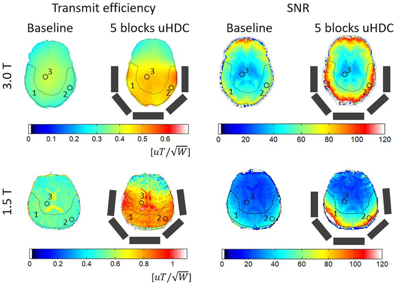
Human brain imaging studies were performed with six healthy subjects with and without the placement of five uHDC blocks, as shown in Figure 3g. For statistical analysis of the in vivo data, a paired t-test (6 subjects, two-tailed) on the SNR in several representative regions of interest (ROIs) and transmission power used with and without uHDC materials are presented in Table 1. All subjects provided informed written consent to the study protocol approved by the institutional review board of Penn State College of Medicine.
Table 1.
Percent Increase of B+1, SNR, and RF Power With uHDC Relative to the Baseline In Vivo Results
| 3 T | 1.5 T | |||||
|---|---|---|---|---|---|---|
| RF power (%) | −44 ± 7 (P < 0.01) | −52 ± 4 (P < 0.01) | ||||
| ROI | ROI-1 | ROI-2 | ROI-3 | ROI-1 | ROI-2 | ROI-3 |
| Transmit efficiency (%) | 51 ± 9 | 67 ± 9 | 38 ± 12 | 63 ± 7 | 57 ± 6 | 42 ± 10 |
| (P < 0.05) | (P < 0.01) | (P < 0.05) | (P < 0.001) | (P < 0.001) | (P < 0.01) | |
| SNR (%) | 43 ± 8 | 56 ± 19 | 15 ± 12 | 56 ± 25 | 77 ± 32 | 7 ± 9 |
| (P < 0.05) | (P < 0.05) | (P = 0.16) | (P < 0.05) | (P < 0.05) | (P = 0.21) | |
Note: ROI-1 to ROI-3 are shown in Figure 7.
RESULTS
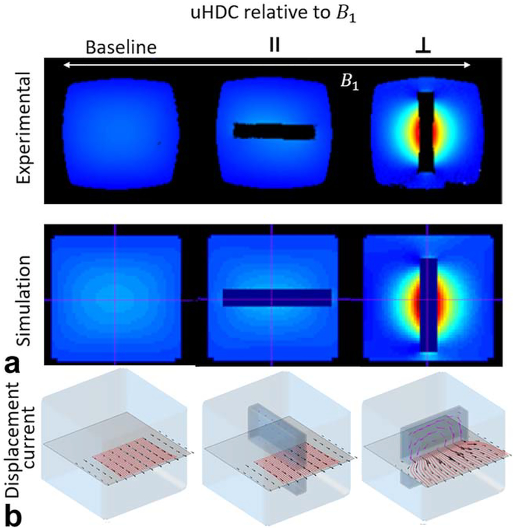
Figure 4a shows the experimental and simulated B+1 field at 3T without (left) and with a block (ɛr =1200) placed either parallel (middle) or perpendicularly=(right) to the B1 field of the RF coil, as illustrated in Figures 3b and 3c of Phantom 1, respectively. By embedding the uHDC blocks into the phantom, the orientation dependence of its effect on the B1 field of the RF coils can be directly visualized. Coronal images show the B1 field enhancements with respect to the block orientation. Comparing the images of the baseline, a large increase in B+1 is seen near the block when the uHDC blocks are placed perpendicularly to B1. In contrast, little effect can be seen when the same block is placed parallel to the B1 field. The computer simulations reproduced the experimental results for all of the cases. To understand this orientation dependence, Figure 4b shows the 3D-rendered B+1 along with the vector plots of displacement current density inside the block. When the uHDC block is perpendicular to B1 of the RF coil, per Equation [2], a large, nonconservative electric field E is generated by the flux of the time derivative of the B1 field of the RF coil passing through the block’s largest face. Specifically, the magnitude of the induced E is proportional to total flux enclosed by the circular path (Fig. 1a). The time derivative of the induced E field leads to a displacement current distribution in the uHDC block that is thousands of times greater than that of free space. In turn, per Ampere’s Law in Equation [1], the displacement current as a passive field source produces a B1 field that is in-phase with the B1 field of the RF coil and alters the total B1 field distribution. When the uHDC block is placed parallel to the direction of B1 of the RF coil, however, such effect becomes very small because the cross-sectional area of the uHDC block cutting across the B1 flux lines and the resultant displacement currents are much smaller.
FIG. 4.
a: Experimental and calculated B1 field maps without (left) and with an uHDC block placed parallel (middle) and perpendicular (right) to B1 of the transmission coil. b: Three-dimensional vector plots of calculated B1 (black arrows with red flux lines) in a coronal plane and displacement current, Jd, (red purple arrows) distributions in the uHDC block of corresponding conditions. The B1 enhancement is produced by the large displacement current in the uHDC block when it is perpendicular to B1..
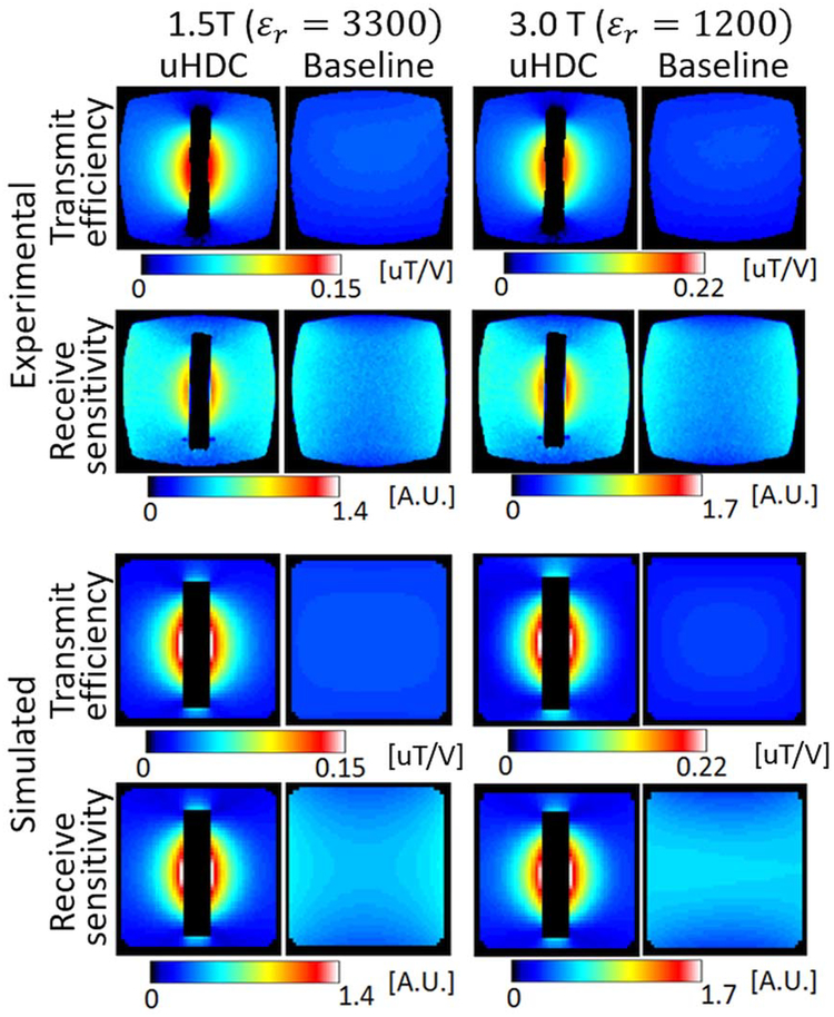
To assess static field strength (RF frequency) dependence of B1 enhancement with respect to the permittivity of uHDC blocks, Figure 5 shows the experimentally measured and numerically simulated Bþ1 and B 1maps of Phantom 1 using blocks with a permittivity of 3300 at 1.5 T and 1200 at 3T, respectively. In each case, the RF power for a given flip angle was experimentally adjusted to maximize the signal from a reference slice and compared with the case with no uHDC block present. As seen in the B+1 and B−1maps of Figure 5, similar B1 enhancement patterns can be achieved at 1.5 T but with a greater permittivity value. The simulated results in the bottom rows reproduced the experimental results. Conversely, if the uHDC blocks were switched at their respective field strengths in Figure 5, such a consistent B1 enhancement is no longer evident. As shown in the experimentally measured B1 maps in Supporting Figure S1 at 1.5 T with uHDC block of ɛr =1200, the enhancement of B1 is greatly reduced compared with the uHDC block with ɛr = 3300 at the same field strength. In contrast, at 3T, the uHDC block with ɛr =3300 produced a strong but extremely inhomogeneous=B1 field. In these two cases, the effect of the uHDC blocks on B1 field distribution is undesirable.
FIG. 5.
Measured and calculated B1 maps with and without uHDC with different permit-tivity at 1.5 and 3T using Phantom 1. The uHDC block with relative permittivity 3300 produced similar enhancement of B1 field at 1.5 T than those at 3T with uHDC block with relative permittivity = 1200.
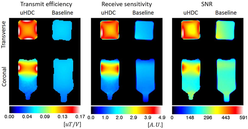
To demonstrate how B1 field enhancement translates to image SNR, Figure 6 shows experimentally measured B+1, B−1, and SNR maps of Phantom 2 at 1.5 T, without and with blocks, having a permittivity of 3300 in trans-verse and coronal views. In this case, the uHDC blocks enclosed only the lower half of the bottle. The SNR is increased by approximately 100% in the peripheral regions near the blocks, and 40 to 50% in the center in the enclosed region. Interestingly, only a 5 to 10% reduction of transmit efficiency was observed in the region that is not enclosed by the blocks. The transmit power used to acquire the images with uHDC blocks is strongly reduced: a 27-fold reduction when compared with the baseline case.
FIG. 6.
Experimentally measured transmit efficiency, receive sensitivity, and SNR maps at 1.5 T using Phantom 2 with and without uHDC (ɛr = 3300).
Figure 7 shows a set of representative experimental B+1 and SNR maps of a human brain at 3T (top row) and 1.5 T (bottom row), using five uHDC blocks ɛr =1200 and 3300, respectively, forming a polygon-shaped=arc covering the posterior portion of the human head as illustrated in Figures 3f and 3g. The transmit RF power was reduced by 43.7 ± 7.2% at 3T of the value without the blocks, and by 52 ± 4.4% at 1.5 T, respectively. Because the enhancements vary spatially, especially in SNR by the receive array coil, three representative ROIs were selected to assess the transmit efficiency and SNR enhancements quantitatively. As shown in Figure 7, ROI-1 is a large crescent drawn in the general enhanced region with uHDC blocks. Two additional ROIs are 2-cm diameter circles, each positioned in the peripheral region where enhancement is the strongest and central region where enhancement is the lowest. The average values of the transmit efficiency and SNR in each ROI are given in Table 1. At 3T with an eight-channel receive head coil, the transmit efficiency and SNR in ROI-1 were significantly improved by 50.9 ± 9.4% and 42.8 ± 8%, respectively. A greater SNR improvement is seen in the cortical areas near the blocks (50–80%) than in the center of the brain where the SNR improvement is statistically insignificant. Similarly, at 1.5 T using five uHDC blocks with a permittivity of 3300 with a 12-channel receive coil, the enhancement in transmit efficiency is approximately 30 to 50% (+62.6 ± 6.5% in ROI-1) and SNR is between 40 and over 116% (+56.2 ± 25% in ROI-1) in the covered regions of the subject’s brain.
FIG. 7.
Experimental transmission efficiency and SNR maps from a human brain (skull and CSF stripped) at 3 and 1.5 T without (left of each pair) and with (right of each pair) uHDC configuration consisting of five blocks drawn as gray rectangles. Three ROIs (1, crescent; 2, cortex; and 3, center of brain) were selected carefully to avoid anatomical biases for regional quantitative comparisons in transmit efficiency and SNR given in Table 1.
The uHDC blocks used here are lossy, which induced additional noise into the acquired images. To assess this effect, the changes of the noise level obtained in the prescan in each channel of the receive coil with and without uHDC block for Phantom 2 and human head imaging experiments are given in Table 2 (each for a single exemplary case). As indicated, significant noise level increases (10–30%) were detected from each receive channel, which evidently offset the signal increase as a result of the B1 field enhancement. These results highlight the importance of the reduction of the dielectric loss of uHDC materials in the future, for further improvement.
Table 2.
Percent Noise Level Change From Each Channel of the Receive Coil by Introducing Four uHDC Blocks to the Phantom (as Shown in Figs. 3d and 3e) and Five uHDC Blocks to a Human Head Imaging (as Shown in Figs. 3f and 3g) at 3T
| Coil element | Phantom (%) | In vivo (%) |
|---|---|---|
| 1 | 7.54 | 4.01 |
| 2 | 10.97 | 26.48 |
| 3 | 20.00 | 17.70 |
| 4 | 21.59 | 25.48 |
| 5 | 26.13 | 25.84 |
| 6 | 16.27 | 27.21 |
| 7 | 17.11 | 23.80 |
| 8 | 13.38 | 7.29 |
| Average ± SD | 16.62 ± 5.61 | 19.73 ± 8.62 |
Note: The noise level from each channel is the standard deviation (SD) of noise acquired from prescans, during which time the excitation pulse was absent.
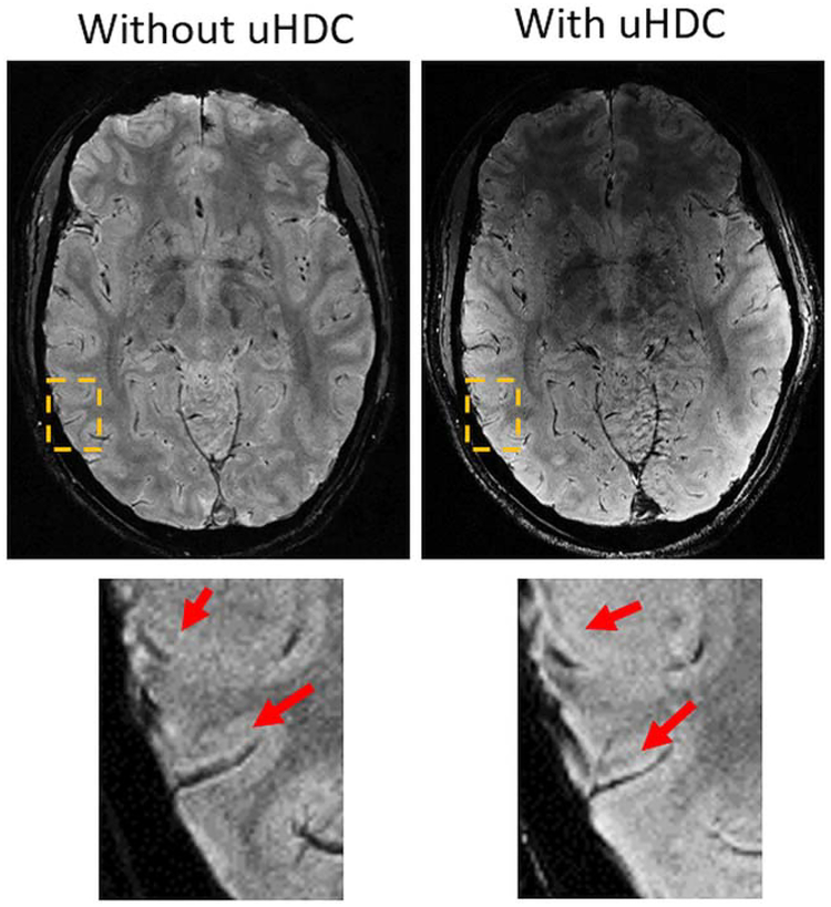
With the enhancement of SNR in the cortical area, a 0.3 × 0.3 × 0.75 mm T*2-weighted high-resolution brain image was acquired with and without the five uHDC blocks (ɛr = 1200) at 3T, as shown in Figure 8. As demonstrated in the zoomed-in images in the cortex, detailed layered structures that were previously observed at 7T (38) can now be clearly visualized.
FIG. 8.
High-resolution (0.31 × 0.31 × 0.75 mm3) T2*gradient-echo images of the brain acquired at 3T without (left) and with uHDC blocks (ɛr = 1200) (right). With improved SNR, the layer structures in the cortex can be seen more clearly (arrows) while RF transmission power was reduced by 45%.
DISCUSSION
As demonstrated with experimental and computer modeling data at both 3 and 1.5 T, uHDC materials can enhance the B1 field within its vicinity by focusing the flux of the RF coils. Surrounding the sample with uHDC produced a several-fold improvement of total transmit efficiency of the body coil, and a significant SNR improvement of the standard receive array coils. This effect is of great clinical interest, as it could speed up many body imaging protocols in which the total specific absorption rate is often a limiting factor for faster acquisitions. For example, as seen in Figure 6, a several-fold enhancement of the transmission field, B+1, can be achieved, which could eliminate the total specific absorption rate constraint for most sequences.
Using uHDC material with permittivity up to 1200 for 125 MHz at 3T, we demonstrated a significantly greater RF field enhancement than previous studies using water or other water-based mixtures of high dielectric materials at 3 or 7T. Therefore, a greater enhancement of the RF field could be achieved with even higher permittivity materials. However, an identical experiment with Phantom 1 using an uHDC block with a permittivity of 3300 at 3T produced an extremely inhomogeneous B1 field distribution, as shown in Supporting Figure S1. This phenomenon is likely to be caused by the destructive interferences as a result of the phase delay of B1 field by the uHDC blocks. Clearly, a systematic investigation into this phenomenon is needed in future studies. Thus, there should be an optimal permittivity and geometry for B1 field enhancement for a given field strength and receive coils. The significant B1 field enhancement in this study was obtained only with uHDC material available commercially with standard receive coils. Thus, the results presented here can only serve as a proof of concept, and the experimental conditions for data acquisition are far from optimal. Future development of customized uHDC materials with optimal permittivity and geometry will, no doubt, further improve the B1 enhancement achieved here.
As seen in our theoretical analysis in Equation [6], the contribution of displacement current to the RF field is quadratically dependent on the operating frequency of the MRI system and linearly dependent on the permittivity of the uHDC material. This predicts that higher permittivity materials are needed to generate a similar B1 enhancement for relatively lower field applications. Our experimental and computer modeling results suggested the same trend. For example, both computer modeling and experimental measurements in Figure 5 showed that a uHDC block with a relative permittivity of 3300 at 1.5 T produced a similar pattern of B1 enhancement to those with a permittivity 1200 at 3T. Currently, it is possible to engineer materials with permittivity as high as 20,000 (39). Thus, uHDC materials could provide benefits for lower field MRI, as SNR is the major limitation for these systems.
In principle, the contribution to the RF field in the sample induced by the displacement current in the uHDC material is proportional to the total flux of the temporal derivative of B1 passing through the uHDC block. Thus, the enhancement of uHDC material should be dependent on its orientation with respect to the direction of the B1 produced by the RF coil. As demonstrated by the vector plots in Figure 4, when the uHDC block is parallel to B1, the displacement current and resultant B1 enhancement are much smaller than the case when the block is perpendicular to B1. Specifically, in our example, the magnitude of the induced E is proportional to total flux enclosed by the circular path (Fig. 1a). The time derivative of the induced E field leads to a displacement current distribution inside the uHDC block that is thousands of times greater than that of free space, because of its ultrahigh permittivity. In turn, per Ampere’s Law in Equation [1], the displacement current as a passive field source produces a B1 field that is in-phase with the B1 field of the RF coil and alters the total B1 field distribution. When the same uHDC block is placed parallel to the direction of B1 of the RF coil, however, such effect becomes very small, because the cross-sectional area of the uHDC block that cuts across the B1 flux lines and the resultant displacement currents are much smaller.
It should be noted that Equation [1] is expressed in the integral form to emphasize the near-field condition in which the electromagnetic quantities (conductive current, E and B1 field) are spatially distributed in separated regions, such as coil conductors, uHDC blocks, and the sample. Notice also that the wave behavior observed in the frequency regime at 7T in human head is only marginally observable at 1.5 and 3T. Thus, it is appropriate to conduct our theoretical analysis based on quasi-static approximation. Under such conditions, the displacement current contribution to B1 field in the sample has been minimal, as its magnitude is much smaller in free space than that of the conductive current in the coils. Once we introduce uHDC materials into RF coils, such that the displacement current in the material can be magnified several thousand-fold, its influence on the RF field inside the sample significantly increases as demonstrated here. The basic principle for RF field enhancement by the uHDC material is its focusing effect through the displacement current. As shown in Equation [6], the displacement current–induced field is in-phase with the RF field of the coil. Therefore, with the proper coil-uHDC material configuration, the RF field can be focused into the sample.
This work provides experimental data for a proof of concept of RF field enhancement using uHDC materials. To translate this technology into routine clinical and scientific investigations, however, there are several engineering challenges that must be addressed. We showed a significantly reduced transmit RF power when using the uHDC material as a result of the highly increased B+1. Although the B−1 fields were also enhanced to a similar level, the average SNR in the phantoms and in the in vivo study was also increased, but lower than anticipated. In these cases, as indicated in Table 2, additional dielectric loss was also introduced in the uHDC material that significantly offset some of the SNR gains. Because the uHDC materials used in this study are formulated for other applications at operating frequencies far from the MRI frequency regime, they are not optimal for MRI applications. With further development of customized uHDC materials for applications at specific field strength (operating frequency) with reduced dielectric loss, the SNR can be further improved to levels close to theoretical predication, as indicated by the computer simulations. Comparing the B1 enhancement in Phantom 2, in which the sample was closely surrounded by uHDC blocks, the SNR improvement in human brain is significantly lower. This discrepancy, in addition to significant contribution of physiological noise, may also be partially because the geometry of the uHDC blocks used in this study did not conform to the human head. In particular, the human brain data were acquired with five separated uHDC blocks placed under and around the head in a standard clinical coil, which is clearly far from a realistic implementation of uHDC materials for human studies. Evidently, a large amount of work must be carried out to optimize the uHDC material electric properties and geometries along with RF coil configurations for applications of specific body anatomy. Another related issue is the space occupied by and the weight added to the RF coil could introduce some practical use issues. Thus, to maximize the benefits and minimized these impeding issues, several lines of future investigations should focus on finding an optimal combination of formulations and geometries of uHDC materials with customized RF coil design.
CONCLUSIONS
We demonstrated with experimental results and theoretical analysis that by using uHDC materials, we achieved remarkable improvements in RF transmission efficiency and image SNR, which can significantly benefit MRI research and clinical applications. Under suboptimal conditions, we experimentally demonstrated that the SNR in the human brain cortex could nearly be doubled without issues of stronger magnetic susceptibility artifacts and elevated specific absorption rate concerns. Thus, incorporation of high dielectric materials is a simple and low-cost approach that could further improve current RF technology.
Supplementary Material
Acknowledgments
Grant sponsor: NIH; Grant numbers: R24 MH106049; R24 MH106049-S1; Grant sponsor: The Penn State Hershey Neuroscience Institute.
Footnotes
SUPPORTING INFORMATION
Additional Supporting Information may be found in the online version of this article.
REFERENCES
- 1.Yang Q, Rupprecht S, Luo W, Sica C. Radiofrequency field enhancement with high dielectric constant (HDC) pads in a receive array coil at 3.0 T. J Magn Reson Imaging 2013;38:435–440. [DOI] [PMC free article] [PubMed] [Google Scholar]
- 2.Brink W, Webb A. Electromagnetic analysis of dielectric shimming using high permittivity materials. In Proceedings of the 21st Annual Meeting of ISMRM, Salt Lake City, Utah, USA, 2013. p. 4375. [Google Scholar]
- 3.Teeuwisse WM, Brink WM, Webb AG. Quantitative assessment of the effects of high-permittivity pads in 7Tesla MRI of the brain. Magn Reson Med 2012;67:1285–1293. [DOI] [PubMed] [Google Scholar]
- 4.Cao Z, Luo W, Sica CT, Oh S, Rupprecht S, Carluccio G, Collins CM, Yang QX. Dramatic improvement of parallel imaging with high dielectric material – demonstration with electromagnetic field calculations at 123 MHz. In Proceedings of the 21st Annual Meeting of ISMRM, Salt Lake City, Utah, USA, 2013. p. 2802. [Google Scholar]
- 5.Aandal GE, Sandhu GS, Novak RD, Nakamoto D, Landeras L, Griswold MA, de Heer P, Webb AG, Gulani V. Clinical evaluation of high permittivity pads for improving abdominal image quality at 3T. In Proceedings of the 21st Annual Meeting of ISMRM, Salt Lake City, Utah, USA, 2013. p. 1589. [Google Scholar]
- 6.Brink WM, van der Jagt AMA, Versluis MJ, Verbist BM, Webb AG. High permittivity dielectric pads improve high spatial resolution magnetic resonance imaging of the inner ear at 7T. Invest Radiol 2014;49:271–277. [DOI] [PubMed] [Google Scholar]
- 7.Brink WM, Webb AG. High permittivity pads reduce specific absorption rate, improve B1 homogeneity, and increase contrast-to-noise ratio for functional cardiac MRI at 3T. Magn Reson Med 2014;71: 1632–1640. [DOI] [PubMed] [Google Scholar]
- 8.Brink WM, van den Brink JS, Webb AG. The effect of high-permittivity pads on specific absorption rate in radiofrequencyshimmed dual-transmit cardiovascular magnetic resonance at 3T. J Cardiovasc Magn Reson 2015;17:82. [DOI] [PMC free article] [PubMed] [Google Scholar]
- 9.Yu Z, Xin X, Collins CM. Potential for high-permittivity materials to reduce local SAR at a pacemaker lead tip during MRI of the head with a body transmit coil at 3T. Magn Reson Med 2017;78:383–386. [DOI] [PMC free article] [PubMed] [Google Scholar]
- 10.Alsop DC, Connick TJ, Mizsei G. A spiral volume coil for improved RF field homogeneity at high static magnetic field strength. Magn Reson Med 1998;40:49–54. [DOI] [PubMed] [Google Scholar]
- 11.Schmitt M, Feiweier T, Horger W, Krueger G, Schoen L, Lazar RKB. Improved uniformity of RF distribution in clinical whole body-imaging at 3T by means of dielectric pads. In Proceedings of the 12th Annual Meeting of ISMRM, Kyoto, Japan, 2004. p. 11. [Google Scholar]
- 12.Yang QX, Mao W, Wang J, Smith MB, Lei H, Zhang X, Ugurbil K, Chen W. Manipulation of image intensity distribution at 7.0 T: passive RF shimming and focusing with dielectric materials. J Magn Reson Imaging 2006;24:197–202. [DOI] [PubMed] [Google Scholar]
- 13.Yang QX, Wang J, Wang J, Collins CM, Wang C, Smith MB. Reducing SAR and enhancing cerebral signal-to-noise ratio with high permittivity padding at 3T. Magn Reson Med 2011;65:358–362. [DOI] [PMC free article] [PubMed] [Google Scholar]
- 14.de Heer P, Brink WM, Kooij BJ, Webb AG. Increasing signal homogeneity and image quality in abdominal imaging at 3T with very high permittivity materials. Magn Reson Med 2012;68:1317–1324. [DOI] [PubMed] [Google Scholar]
- 15.Teeuwisse WM, Brink WM, Haines KN, Webb AG. Simulations of high permittivity materials for 7T neuroimaging and evaluation of a new barium titanate-based dielectric. Magn Reson Med 2012;67:912–918. [DOI] [PubMed] [Google Scholar]
- 16.Haines K, Smith NB, Webb AG. New high dielectric constant materials for tailoring the B1 þ distribution at high magnetic fields. J Magn Reson 2010;203:323–327. [DOI] [PubMed] [Google Scholar]
- 17.Luo W, Lanagan M, Sica C, Ryu Y, Oh S, Ketterman M, Yang Q, Collins C. Permittivity and performance of dielectric pads with sintered ceramic beads in MRI: early experiments and simulations at 3T. Magn Reson Med 2013;70:269–275. [DOI] [PMC free article] [PubMed] [Google Scholar]
- 18.Yang Q, Collins C, Lanagan M, Herse Z, Rupprecht S, Luo W, Ryu YC, Patel M, Vesek J. MRI enhancement via high dielectric constant (e r = 510) pad at 3T : brain imaging. In Proceedings of the 20th Annual Meeting of ISMRM, Melbourne, Australia, 2012. p. 2702. [Google Scholar]
- 19.McGEARY RK. Mechanical packing of spherical particles. J Am Ceram Soc 1961;44:513–522. [Google Scholar]
- 20.Simpkin R Derivation of Lichtenecker’s logarithmic mixture formula from Maxwell’s equations. IEEE Trans Microw Theory Tech 2010;58: 545–550. [Google Scholar]
- 21.Luo W, Guo J, Randall C, Lanagan M. Effect of porosity and micro-structure on the microwave dielectric properties of rutile. Mater Lett 2017;200:101–104. [Google Scholar]
- 22.Rupprecht S, Sica CT, Sahul R, Kwon S, Lanagan MT, Yang QX. Drastic enhancement and manipulation of RF Field with ultra high dielectric constant (UHDC) material at 3T. In Proceedings of the 21st Annual Meeting of ISMRM, Salt Lake City, Utah, USA, 2013. p. 396. [Google Scholar]
- 23.Sica C, Rupprecht S, Luo R, Cao Z, Sahul R, Kwon S, Lanagan M, Collins C, Yang Q. In-vivo evaluation of a new high dielectric constant material for local enhancement of B1 þ and SNR at 3T. In Proceedings of the 21st Annual Meeting of ISMRM, Salt Lake City, Utah, USA, 2013. p. 4377. [Google Scholar]
- 24.Koolstra K, Börnert P, Brink W, Webb A. Improved image quality and reduced power deposition in the spine at 3T using extremely high permittivity materials. Magn Reson Med 2018;79:1192–1199. [DOI] [PMC free article] [PubMed] [Google Scholar]
- 25.Lee B-Y, Zhu X-H, Rupprecht S, Lanagan MT, Yang QX, Chen W. Large improvement of RF transmission efficiency and reception sensitivity for human in vivo 31 P MRS imaging using ultrahigh dielectric constant materials at 7T. Magn Reson Imaging 2017;42: 158–163. [DOI] [PMC free article] [PubMed] [Google Scholar]
- 26.Carluccio G, Oh S, Yang Q, Erricolo D, Weiluo R, Collins CM. Near-field wave impedance matching with high-permittivity dielectric materials for optimum transmittance in MRI systems. In Proceedings of the 21st Annual Meeting of ISMRM, Salt Lake City, Utah, USA, 2013. p. 4374. [Google Scholar]
- 27.Haines K, Neuberger T, Lanagan M, Semouchkina E, Webb AG. High Q calcium titanate cylindrical dielectric resonators for magnetic resonance microimaging. J Magn Reson 2009;200:349–353. [DOI] [PubMed] [Google Scholar]
- 28.Aussenhofer SA, Webb AG. An eight-channel transmit/receive array of TE01 mode high permittivity ceramic resonators for human imaging at 7T. J Magn Reson 2014;243:122–129. [DOI] [PubMed] [Google Scholar]
- 29.Schmidt R, Teeuwisse W, Webb A. Quadrature operation of segmented dielectric resonators facilitated with metallic connectors. Magn Reson Med 2017;77:2431–2437. [DOI] [PubMed] [Google Scholar]
- 30.Christ A, Kainz W, Hahn EG, et al. The Virtual Family—development of surface-based anatomical models of two adults and two children for dosimetric simulations. Phys Med Biol 2010;55:N23–N38. [DOI] [PubMed] [Google Scholar]
- 31.Haertling GH. Ferroelectric ceramics: history and technology. J Am Ceram Soc 1999;82:797–818. [Google Scholar]
- 32.Böttger U, Arlt G. Dielectric microwave dispersion in PZT ceramics. Ferroelectrics 1992;127:95–100. [Google Scholar]
- 33.Hakki BW, Coleman PD. A dielectric resonator method of measuring inductive capacities in the millimeter range. IRE Trans Microw Theory Tech 1960;MTT-8:402–410. [Google Scholar]
- 34.Lanagan MT, Kim JH, Jang S-J, Newnham RE. Microwave dielectric properties of antiferroelectric lead zirconate. J Am Ceram Soc 1988; 71:311–316. [Google Scholar]
- 35.Sacolick LI, Wiesinger F, Hancu I, Vogel MW. B1 mapping by Bloch-Siegert shift. Magn Reson Med 2010;63:1315–1322. [DOI] [PMC free article] [PubMed] [Google Scholar]
- 36.Jankiewicz M, Gore JC, Grissom WA. Saturation pulse design with explicit sensitivity maximization for Bloch-Siegert B1 mapping. In Proceedings of the 20th Annual Meeting of ISMRM, Melbourne,Australia, 2012. p. 3362. [Google Scholar]
- 37.Kellman P, McVeigh ER. Image reconstruction in SNR units: a general method for SNR measurement. Magn Reson Med 2005;54:1439–1447. [DOI] [PMC free article] [PubMed] [Google Scholar]
- 38.Duyn JH, van Gelderen P, Li T-Q, de Zwart JA, Koretsky AP, Fukunaga M. High-field MRI of brain cortical substructure based on signal phase. Proc Natl Acad Sci U S A 2007;104:11796–11801. [DOI] [PMC free article] [PubMed] [Google Scholar]
- 39.Adams TB, Sinclair DC, West AR. Giant barrier layer capacitance effects in CaCu3Ti4O12 ceramics. Adv Mater 2002;14:1321–1323. [Google Scholar]
Associated Data
This section collects any data citations, data availability statements, or supplementary materials included in this article.


