

Abstract
The dome of Santa Maria del Fiore, Florence Cathedral, was built between 1420 and 1436 by architect Filippo Brunelleschi and it is now cracking under its own weight. Engineering efforts are under way to model the dome's structure and reinforce it against further deterioration. According to some scholars, Brunelleschi might have built reinforcement structures into the dome itself; however, the only known reinforcement is a wood chain 7.75 m above the springing of the Cupola. Multiple scattering muon radiography is a non-destructive imaging method that can be used to image the interior of the dome's wall and therefore ascertain the layout and status of any iron substructure in it. A demonstration measurement was performed at the Los Alamos National Laboratory on a mock-up wall to show the feasibility of the work proposed, and a lightweight and modular imaging system is currently under construction. We will discuss here the results of the demonstration measurement and the potential of the proposed technique, describe the imaging system under construction and outline the plans for the measurement.
This article is part of the Theo Murphy meeting issue ‘Cosmic-ray muography’.
Keywords: Cupola, Santa Maria del Fiore, muon, cosmic rays, Brunelleschi's dome
1. Introduction
The Cathedral of Santa Maria del Fiore (Saint Mary of the Flower) was founded in 1296. Its majestic dome (‘Cupola’ in Italian) was constructed between 1420 and 1436 under the direction of Filippo Brunelleschi and now dominates the Florence skyline.
The Cupola consists of two shells, with the inner shell 2.25 m and the outer shell 0.8 m thick at the base, separated by a 1.2 m space and connected by spurs or buttresses. The Cupola is built out of large blocks of sandstone for the first 7 m above its base. From there to the base of the lantern, the masonry is made of clay bricks of different sizes and arranged according to different patterns with the purpose of ensuring the Cupola's structural stability. In order to oppose the centrifugal thrust and to provide an adequate hoop strength, Brunelleschi reinforced the dome using a wood chain located in the space between the two shells, 7.75 m above the base of the Cupola.
According to some scholars, there might also be iron chains inside the masonry, although investigations with metal detectors have failed to provide conclusive evidence. Based on some documents from the period of the construction, thousands of Florentine pounds of iron (1 Florentine pound = 0.34 kg) were purchased during the construction of the dome though only a small fraction of it is currently accounted for [1].
The dome has been affected by cracks for centuries; some of them are currently 6–8 cm wide and their width increases at a rate of 7.5 mm/century [1]. Figure 1 adapted from [1] shows the location of such cracks.
Figure 1.

Plan (a) and cross-section (b) of Santa Maria del Fiore showing the location of the main cracks. Reprinted from reference [1] with permission.
Detailed knowledge of the structure of the Cupola would benefit the computational models that are used to evaluate its behaviour under static and dynamic (earthquake) conditions. Only the parts of the monument that are directly visible have been extensively studied because techniques capable of imaging the interior structure are limited. Brunelleschi was very secretive about his work and purposely did not leave technical drawings.
We plan to use multiple scattering muon radiography (MSMR) to image the inside of the dome's walls. Cosmic-ray muons are naturally produced in the atmosphere by the interactions of primary cosmic rays with the nuclei present in the atmosphere itself. They have no hadronic interaction with nucleons, and their relatively large mass (of 105.6 MeV c−2—about 200 times the mass of an electron) limits energy loss due to bremsstrahlung radiation. These properties allow energetic muons to penetrate large amounts of material that are inaccessible to other particles. Muons possess an electric charge and undergo Coulomb scattering off nuclei as they pass through matter.
The first use of cosmic-ray muons for radiography was in 1955 when George measured muon attenuation to determine the overburden of rock above a tunnel [2]. This was followed by Alvarez et al., who used this method to confirm that the Second Pyramid of Giza did not contain any undiscovered chambers [3], and more recently by several groups examining geologic features [4–10]. A recent article [11] shows how cosmic-ray muons were used to find a void inside Khufu's pyramid at Giza.
A different method, developed at Los Alamos National Laboratory (LANL), uses measurements of the multiple scattering angles of individual muons passing through an object to create tomographic images of the object's interior structure [12]. This technique was originally developed to inspect cargo containers for illicit trafficking of nuclear material [13,14], and has since been applied to the detection of special nuclear materials [15], used to image nuclear reactors [16,17] and spent nuclear fuel [18,19].
The method is based on the fact that muons, when travelling through materials, undergo many individual Coulomb scatterings with the charged atomic nuclei. As a result, they deviate from their initial trajectory and exit the material at an angle with respect to their initial trajectory.
The theory of multiple Coulomb scattering, developed by Moliere and Bethe [20–22], predicts, for the muons that go through an object, a Gaussian polar angle distribution with tails. The dominant part of such a distribution can be described by:
where θ is the polar angle and θ0 is given by
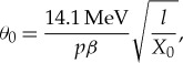 |
with p being the muon momentum, β its velocity and X0 the radiation length for the material. The difference in atomic number between materials results in a difference in their radiation length. By measuring the distribution of cosmic muon scattering angles after they traverse an object of interest, an image of the object itself can be reconstructed as described in [23].
By using MSMR on the inner wall of the Florence dome, we will be able to identify and image iron elements inside the masonry of the dome.
In order to prove the feasibility of this approach, a demonstration measurement was performed at LANL during the summer of 2015.
2. Feasibility study
If any reinforcement structure is present in the masonry of the Cupola's wall, it most likely has to be located inside the inner shell. This shell is much thicker than the outer shell and thus plays a more important role in sustaining the whole structure.
A concrete wall having the same thickness, in radiation lengths, as the inner wall of the dome was built. Both the experimental set-up and the measurement are thoroughly described in [24].
Three iron bars were placed inside this mock-up wall. The bars had rectangular or square cross sections with different sizes: 4.76 cm × 5 cm, 10 cm × 10 cm and 2 cm × 3 cm. The LANL Mini Muon Tracker (MMT) [25] was used to perform the demonstration measurement. The detector consists of two trackers made of aluminium drift tubes. The two trackers were deployed on opposite sides of the wall, as shown in figure 2, and collected data for 35 days.
Figure 2.

The MMT taking data around the mock-up of the Cupola wall. The lower detector is still enclosed in a shed after a previous measurement campaign during which it needed to be weather-proof.
An image of the vertical plane passing through the iron bars was reconstructed as explained in [23] and the resulting image is shown in figure 3a.
Figure 3.

(a) Image of the three iron bars described in the text inside the concrete mock-up wall, obtained using 35 days of data collected with the MMT. (b) Image of the same three bars obtained from the output of a Monte Carlo simulation.
All the three iron bars are visible, including the thinnest one. For comparison, a Monte Carlo simulation of the same experimental set-up was performed and its data were analysed with the same analysis technique. The areal density image obtained from the Monte Carlo simulation is shown in figure 3b, whereas a projection along the x-axis of both the experimental data and the simulated results is shown in figure 4.
Figure 4.

The integral of the areal density obtained from the data (blue) and from the Monte Carlo simulation (red).
The good agreement between the data and the simulation demonstrates that the technique is well understood and that the performances of future measurements can be confidently predicted. This measurement furthermore demonstrates that iron elements inside the inner wall of the dome of the Florence Cathedral could be located and imaged using a pair of muon trackers similar to those used to perform the aforementioned measurement. The time necessary to produce an image of the volume between the two trackers is about a month.
3. Detector development and prospects for a future measurement
The pair of trackers used to perform the measurement described in the previous section is too heavy and bulky to be transported up to the base of the Cupola and to be operated there. We are assembling two trackers made of carbon fibre drift tubes closed by conductive plastic endcaps: the trackers are modular, and are made of elements small and light enough to be hand carried to the base of the dome through the narrow spiral staircases leading there. Each tracker is made of 576 drift tubes, each one having a diameter of 2.54 cm and a length of 122 cm. Each tube has a 20 µm diameter anode wire at its centre. The tubes are grouped in modules of 24. Each module has been assembled and tested at the LANL. The modules will be filled with a mixture of Ar, CF4 and ethane and operated at 1 bar of pressure. The overall size of each tracker, including the electronics, will be 137 cm × 137 cm × 30.5 cm and its weight will be around 130 kg. A mechanical drawing of a single tracker is shown in figure 5a and a picture of one tracker is shown in figure 5b.
Figure 5.

Mechanical drawing showing one of the two LANL trackers (a) and picture of one of the two trackers built (b).
The efficiency and the gain of the drift tubes were monitored and found stable over a month, the time required to obtain a single image of the volume between the two trackers.
The timing of the tiny (few fC) charge pulses produced at the anode wire of each tube will be read out by custom electronic boards, currently being designed by the University of Pennsylvania group, and that information will be used to determine the trajectory of each muon crossing the trackers. The existing image reconstruction software developed by LANL will then be used to obtain radiographic images of the volume between the two trackers.
Once the trackers are fully assembled and tested, they will be shipped to Florence, deployed and operated on two opposite sides of the inner wall of the dome of Santa Maria del Fiore as shown in figure 6. We aim at imaging a vertical slice of the inner shell in rib vault number 4 or 6—both affected by cracks—from the springing of the Cupola up to the first oculus above it: if any reinforcement structure were present inside the dome, it would likely be located in this region, where the centrifugal thrust is strongest.
Figure 6.

Schematic drawing showing the layout of the two muon trackers around the inner wall of the Cupola.
The two trackers will be held in place by support/guide cables. They will be operated at each location for about one month and each measurement will yield a 3D image of the inner wall 1 m × 1 m × 2.25 m in size, the volume between the two trackers. In between different measurements, the trackers will be moved to their next location along the guide cables.
A 25 m vertical slice of the dome will therefore require about 2 years to be fully imaged.
The data taking and analysis will be performed by a team of researchers from LANL, the University of Florence and the University of Pennsylvania.
The scientists at the University of Florence are currently evaluating the feasibility and the potential of a complementary measurement using muon absorption radiography [26]. The two measurements together will provide an independent verification of the existence and location of metal reinforcement elements inside the Cupola wall. The measurement will begin once the detectors are ready, subject to the availability of funding.
Data accessibility
This article has no additional data.
Authors' contributions
E.G. performed the demonstration measurement described, is leading the construction of the new detector and drafted the manuscript. J.D.B. performed the demonstration measurement described and is assembling the new lightweight detector. C.B. coordinates the cooperation between the US and Italian institutions and the deployment of the measurement system in Santa Maria del Fiore. L.B. and R.D'A. will perform the complementary measurement mentioned in the text. J.M.D. is assembling the new lightweight detector. C.M. invented the imaging technique used and conceived the lightweight detector. K.P.-R. designed and built most of the lightweight detector. D.C.P. is assembling the new lightweight detector. V.V. is a member of the Board of the Opera del Duomo and coordinates the actual measurement to be performed. R.V.B., F.M.N., C.M., N.B., A.C., M.F., G.M., J.O., T.P., M.B.R., A.R. and T.S. designed, developed and tested the read-out electronics. All authors read and approved the manuscript.
Competing interests
The authors declare that they have no competing interests.
Funding
This work was funded by the Laboratory Directed Research and Development program at Los Alamos National Laboratory and by the University of Pennsylvania.
Disclaimer
This is Los Alamos Publication LA-UR-18-28207.
References
- 1.Fanelli GFM. 2004. Brunelleschi's cupola. Past and present of an architectural masterpiece. Florence, Italy: Mandragora. [Google Scholar]
- 2.George EP. 1955. Cosmic rays measure overburden of tunnel. Commonw. Eng. 455–457. [Google Scholar]
- 3.Alvarez LW, et al. 1970. Search for hidden chambers in the pyramids. Science 167, 832–839. ( 10.1126/science.167.3919.832) [DOI] [PubMed] [Google Scholar]
- 4.Nagamine K, Iwasaki M, Shimomura K, Ishida K. 1995. Method of probing inner-structure of geophysical substance with the horizontal cosmic-ray muons and possible application to volcanic eruption prediction. Nucl. Instrum. Methods A 356, 585–595. ( 10.1016/0168-9002(94)01169-9) [DOI] [Google Scholar]
- 5.Lesparre N, Gibert D, Marteau J, Déclais Y, Carbone D, Galichet E. 2010. Geophysical muon imaging: feasibility and limits. Geophys. J. Int. 183, 1348–1361. ( 10.1111/j.1365-246X.2010.04790.x) [DOI] [Google Scholar]
- 6.Nishiyama R, Tanaka Y, Okubo S, Oshima H, Tanaka HK, Maekawa T. 2014. Integrated processing of muon radiography and gravity anomaly data toward the realization of high-resolution 3-D density structural analysis of volcanoes: Case study of Showa-Shinzan lava dome, Usu, Japan. J. Geophys. Res. Solid Earth 119, 699–710. ( 10.1002/2013JB010234) [DOI] [Google Scholar]
- 7.Carloganu C, et al. (TOMUVOL Collaboration). 2013. Towards a muon radiography of the Puy de Dome. Geosci. Methods Instrum. Data Syst. 2, 55–60. ( 10.5194/gi-2-55-2013) [DOI] [Google Scholar]
- 8.Ambrosino F, et al. 2014. The MU-RAY project: detector technology and first data from Mt. Vesuvius. J. Instrum. 9, C02029 ( 10.1088/1748-0221/9/02/C02029) [DOI] [Google Scholar]
- 9.Oláh L, Barnaföldi GG, Hamar G, Melegh HG, Surányi G, Varga D. 2013. Cosmic muon detection for geophysical applications. Adv. High Energy Phys. 2013, Article ID 560192 ( 10.1155/2013/560192) [DOI] [Google Scholar]
- 10.Guardincerri E, et al. 2017. 3D Cosmic ray muon tomography from an underground tunnel. Pure Appl. Geophys. 174, 2133–2141. ( 10.1007/s00024-017-1526-x) [DOI] [Google Scholar]
- 11.Morishima K, et al. 2017. Discovery of a big void in Khufu's Pyramid by observation of cosmic-ray muons. Nature 552, 386–390. ( 10.1038/nature24647) [DOI] [PubMed] [Google Scholar]
- 12.Schultz LJ, Borozdin KN, Gomez JJ, Hogan GE, Mcgill JA, Morris CL, Priedhorsky WC, Saunders A, Teasdale ME. 2004. Image reconstruction and material Z discrimination via cosmic ray muon radiography. Nucl. Instrum. Methods A 519, 687–694. ( 10.1016/j.nima.2003.11.035) [DOI] [Google Scholar]
- 13.Borozdin KN, Hogan GE, Morris C, Priedhorsky WC, Saunders A, Schultz LJ, Teasdale ME. 2003. Surveillance: radiographic imaging with cosmic-ray muons. Nature 422, 277 ( 10.1038/422277a) [DOI] [PubMed] [Google Scholar]
- 14.Priedhorsky W, et al. 2003. Detection of high-Z objects using multiple scattering of cosmic ray muons. Rev. Sci. Instrum. 74, 4294–4297. ( 10.1063/1.1606536) [DOI] [Google Scholar]
- 15.Guardincerri E, et al. 2015. Detecting special nuclear material using muon-induced neutron emission. Nucl. Instrum. Methods A 789, 109–113. ( 10.1016/j.nima.2015.03.070) [DOI] [Google Scholar]
- 16.Perry J, et al. 2013. Imaging a nuclear reactor using cosmic ray muons. J. Appl. Phys. 113, 184909 ( 10.1063/1.4804660) [DOI] [Google Scholar]
- 17.Morris CL, et al. 2014. Analysis of muon radiography of the Toshiba nuclear critical assembly reactor. Appl. Phys. Lett. 104, 024110 ( 10.1063/1.4862475) [DOI] [Google Scholar]
- 18.Durham JM, et al. 2015. Cosmic ray muon imaging of spent nuclear fuel in dry storage casks. J. Nucl. Mater. Manage. 44, 5–12. [Google Scholar]
- 19.Durham JM, et al. 2018. Verification of spent nuclear fuel in sealed dry storage casks via measurements of cosmic ray muon scattering. Phys. Rev. Appl. 9, 044013 ( 10.1103/PhysRevApplied.9.044013) [DOI] [Google Scholar]
- 20.Molière G. 1947. Theorie der Streuung schneller geladener Teilchen I. Einzelstreuung am abgeschirmten Coulomb-Feld (Theory of scattering of fast charged particles I. Single scattering on the shielded Coulomb field). Z. Naturforschung A 2 (3), 133–145. [Google Scholar]
- 21.Molière G. 1948. Theorie der Streuung schneller geladener Teilchen II. Mehrfach- und Vielfachstreuung (Theory of the scattering of fast charged particles II. Repeated and multiple scattering). Z. Naturforschung A 3 (2), 78–97. [Google Scholar]
- 22.Bethe H. 1953. Molière's theory of multiple scattering. Phys. Rev. 89, 1256 ( 10.1103/PhysRev.89.1256) [DOI] [Google Scholar]
- 23.Morris CL, et al. 2013. A new method for imaging nuclear threats using cosmic ray muons. AIP Adv. 3, 082128 ( 10.1063/1.4820349) [DOI] [Google Scholar]
- 24.Guardincerri E, et al. 2016. Imaging the inside of thick structures using cosmic rays. AIP Adv. 6, 015213 ( 10.1063/1.4940897) [DOI] [Google Scholar]
- 25.Perry JO. 2013. Advanced applications of cosmic-ray muon radiography. PhD thesis, The University of New Mexico, Albuquerque, New Mexico.
- 26.Blasi C, Bonechi L, D'Alessandro R, Guardincerri E, Vaccaro V. 2018. Detecting metal elements inside the dome of Santa Maria del Fiore in Florence using cosmic ray muons. IOP Conf. Ser. Mater. Sci. Eng. 364, 01207 ( 10.1088/1757-899X/364/1/012072) [DOI] [Google Scholar]
Associated Data
This section collects any data citations, data availability statements, or supplementary materials included in this article.
Data Availability Statement
This article has no additional data.