Abstract
An adaptive averaging low noise analog front-end (AFE) is presented for central and peripheral nerve recording applications. The proposed topology allows users to trade off, on the fly, between input referred noise and the number of channels via averaging. The new low noise amplifier (LNA) utilizes a complementary doubled input transconductance (gm) topology to effectively increase the noise efficiency factor (NEF) without chopping or use of a costly BiCMOS process. It addresses a disadvantage of the doubled-gm technique by a high input impedance DC-coupled LNA and saves on-chip space for higher density by eliminating AC-coupling capacitors. The proposed technique is particularly suitable for ultra-low noise multichannel recording from the peripheral nervous system (PNS) with channel selection analog multiplexer, where input signal is in tens of μV. A 32-ch proof-of-concept-prototype AFE was fabricated in a 5M2P 130-nm standard CMOS process, occupying 2.4 × 2.5 mm2 together with its control block. The prototype LNA consumes 11 μW from a 1 V supply, providing 3.0 μVrms input referred noise with 61 ΜΩ input impedance, which are desirable for high SNR, to be further improved by the adaptive averaging technique.
Keywords: Low noise amplifier, peripheral nerve recording, noise efficiency factor, closed-loop DC offset rejection, noise averaging, doubled-gm
I. Introduction
PERIPERAL nerve interfacing technology has been developed in the applications, such as the integrated visceral neural network (iVNN), for discovering and manipulating the patient’s peripheral neural network to manage various disorders [1], The iVNN observes both central and peripheral neural activities, and the information acquired by neural network and peripheral nervous system (PNS) can be utilized for brain-machine interfacing (BMI), as a substitute for pharmacological solutions, or used for functional electrical stimulation (FES).
Recording activities from central nervous system (CNS) and PNS have different characteristics in tenus of electrodes, bandwidth, and signal strength. For example, the amplitude of the electroneurogram (ENG) recorded with cuff electrodes typically shows a few tens of μV in amplitude [2], while the action potentials (AP) in CNS are in the order of several hundred μV. with up to 10 kHz bandwidth [3]. Therefore, the analog front-end (AFE) needed to record the peripheral nerve activities should have much lower input referred noise than the AFE used in a conventional neural recording system.
Several techniques have been proposed to reduce the input referred noise of the low noise amplifier (LNA) in the AFE. The LNAs designed in a BiCMOS process show very low noise thanks to the bipolar transistor inputs [4], However, this type of LNA cannot be used in the standard CMOS process with low supply voltage. Although the chopper modulation technique, introduced in [5], can reduce the input referred noise, the input impedance is significantly reduced by the chopping function, which frequency needs to be proportional to the bandwidth of the input signal. Therefore, the signal-to-noise ratio (SNR) drops for higher chopping frequencies, limiting its application to recording lower bandwidth signals up to a few 100 Hz, such as electroencephalogram (EEG) recording.
The complementary-input amplifier was presented to double the input transconductance (gm) with a given bias current [6], [17]. This method can effectively improve the noise efficiency factor (NEF), however, it still degrades the input impedance with the doubled AC-coupling capacitors connected to four input MOSFETs, which are needed to prevent DC offsets at the electrode-tissue interface. The idea of averaging low noise amplifier outputs in the hardware was first introduced in [7], using off-the-shelf components. Although this concept can achieve low input referred noise for peripheral nerve recording, the discrete devices are too bulky for implantation in the body, and it is not able to operate at low supply voltage, resulting in large power consumption at 1.63 mW/ch. In addition, the input impedance of ~10 MΩ for each LNA is insufficient for high impedance electrodes in the impedance range of 10s of kΩ up to a few ΜΩ [8], particularly because the input impedance of the LNA is inversely proportional to the number of channels being combined in parallel for hardware averaging. More recently, an LNA with sub-μVrms noise level was designed with bias current control to provide different input-referred noise levels. However, the telescopic structure is not suitable for low supply voltage operation [9]. Also the input impedance for this particular implementation is inherently low due to its large input capacitance.
In this paper, we present an adaptive averaging low noise amplifier for the recording of both CNS and PNS signals, which equips the high input impedance structure with the doubled input gm for improved NEF. The proposed AFE channels use an adaptive averaging structure to control the level of the input referred noise, depending on the biomedical signal strength. This also has a benefit in long term recording when the neural signals become weaker due to scar tissue formation, resulting in some electrodes becoming non-viable [10]. In this case, we can combine those AFE channels which have lost their input, and improve the SNR in the remaining channels that are still viable. In section II, the adaptive averaging AFE architecture is introduced with the proposed LNA structure for 1 V supply operation. Experimental setup and measurement results with pre-recorded biomedical signals are presented in section III, followed by conclusions.
II. System Architecture
A. Adaptive averaging topology
Fig. 1 shows the schematic diagram of the multi-channel AFE implementation of the adaptive averaging technique. The 32-ch neural recording AFE, in each channel consists of an LNA, a variable-gain amplifier (VGA), and a buffer, which amplify and filter the neural signals with a designated output noise of v2no,AFE, as shown in Fig. 1. In this neural recording AFE, the input referred noise of the individual channel is enough to amplify the CNS neural signals, which typically have ~100 μV amplitude. When the AFE requires lower input referred noise to record much smaller peripheral nerve signals, a number of AFE channels can be combined by a 32-to-n analog multiplexer (MUX) to reduce the input referred noise of the AFE. Considering the output noise of the individual AFE channels, including the LNA and VGA, v2no,AFE the combined m-channel output noise,v2no,AFE,Avg can be presented as,
| 1 |
Fig. 1.
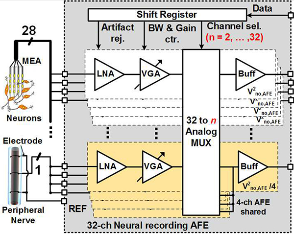
Simplified schematic diagram of the multi-channel AFE with adaptive averaging technique for neural and peripheral nerve recordings.
Since the output noise for each AFE channel, v2noAFE(0), v2noafe(1),..., v2noafe(m-1), is identical and uncorrelated with each other, while the output signal is the same, the effective input referred noise for m-channel combination, v2ni_rms,AFE,Avg, can be presented as,
| 2 |
where m is 32/n, n = 2, 4...32, for the 32-ch neural recording AFE, as shown in Fig. 1.
The adaptive averaging topology has several advantages in terms of achieving low noise and flexibility in practical applications. Instead of the one ultra-low noise amplifier, which either has large size or large power consumption, several LNAs, which overall size and power consumption is close to that of the large LNA, can be purposefully combined or divided by the MUX for the desired application at hand, such as CNS or PNS recording, which require specific low levels of input referred noise. In addition, input referred noise control of the AFE without any additional power consumption is beneficial for implanted devices that store or wirelessly receive a limited amount of power. It should be noted that this hardware averaging method degrades the SNR slightly because the input impedance of each LNA is reduced by a factor of m. Thus, starting with a high input impedance LNA becomes important particularly when electrode and contact impedances are high.
B. DC-coupled input offset rejection LNA
As discussed above, high LNA input impedance is desired to achieve high SNR considering the often high impedance small recording microelectrodes. Moreover, the LNA should be able to eliminate a DC offset of −100 mV to 100 mV at the input, which results from electrode-electrolyte half-cell potentials [13] In the conventional LNA structure with capacitive feedback [11], the DC blocking capacitor for removing this DC offset should be large to provide enough gain and minimize signal attenuation between the blocking capacitor and electrode impedance. This capacitor occupies a large area on chip, and it is not suitable for todays’ dense AFEs with high channel count [12]. Although a few DC-coupled input offset rejection methods are developed to eliminate the DC blocking capacitors [13], [14], most of these circuits only offer open-loop gain, which result in gain inconsistency among different channels.
The proposed closed-loop DC-coupled doubled-gm, LNA schematic is shown in Fig. 2, with all the features needed for it to be used for the proposed adaptive averaging method towards a low noise AFE with fairly small footprint. The first stage consists of a complementary input stage LNA that doubles the input gm for higher NEF and a large open-loop gain of A. The LNA output, Vlna, is low pass filtered (LPF) in a feedback loop with transfer function of β (1+jwR1C2)/(1+jwR1C2+jwR1C2) and high cut-off frequency of f2=1/(2πR1C1). The feedback signal, Vlpf, is subtracted from the input signal, VIN, after a capacitive attenuator to provide high pass filtering (HPF) and amplification with low cut-off frequency and mid-band gain of f3 = 1/(2πR1C2) and A v,lna = A0 = 1+C1/C2, respectively. The closed-loop LNA transfer function can be expressed as,
| 3 |
Fig. 2.
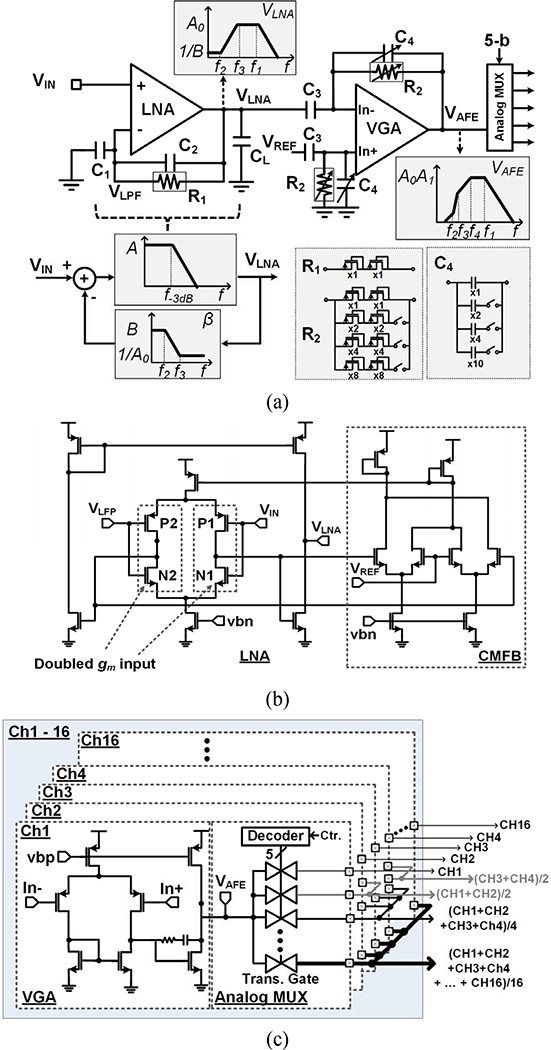
(a) Schematic diagram of the DC-coupled neural recording AFE with input offset rejection, and bode plot of the AFE blocks and its feedback network, (b) Complementary input stage LNA that doubles the input gm for higher NEF. (c) Variable-gain amplifier with closed-loop gain from Ai= 2.4 to 40 and analog multiplexer implemented by a transmission gate array.
Although the DC-coupled LNA can provide sufficient DC offsets rejection at the electrode-electrolyte interface, AC-coupling at the input of the following VGA is desired because the DC offset of the LNA cannot be perfectly removed. The high pass −3dB bandwidth and the overall gain of the AFE can be digitally adjusted by R2 and C4, which follow by the LNA low cut-off frequency at f3. The VGA transfer function can be
| 4 |
providing an overall midband AFE gain of.AAEF = Av,LNa Av,vga.
Both R1 and R2 are implemented using pseudo-resistors to obtain ~GΩ resistance, w ith R2 being 3-bit adjustable for digital control of the HPF. C4 can be changed from 50 fF to 850 fF by 3-bit gain control, according to C3/C4 The DC-coupled LNA structure can, therefore, minimize the effects of neural signals DC drift without large DC blocking capacitors or chopper modulation, maintaining the high input impedance of the LNA, needed for the adaptive averaging scheme, shown in Fig. 1.
C. Doubled-gm architecture
The high NEF of the LNA is desirable to achieve ultra-low noise without large power consmnption. A disadvantage of the doubled input gm technique, which is its doubled DC-coupling capacitors compared to the conventional LNA [6], [11], is overcome by the proposed topology in Fig. 2a by DC-coupled input offset rejection.
The schematics of the doubled input gm LNA is shown in Fig. 2b. The complementary input stage withN1 and P1 doubles the amplifier’s effective gm compared to the conventional amplifier using the same amount of power. The effective input referred noise, v2ni,lna, can be found from [6],
| 5 |
where gmp and gmn are the transconductances of P1 and Nl, respectively.
D. VGA and analog multiplexer
The schematic of the VGA followed by the analog MUX for adaptive averaging is shown in Fig. 2c. The VGA provides closed-loop gain that is adjustable from 2.4 to 40 and HPF from 1 Hz and 400 Hz, each with 3-bit digital control. The analog MUX is implemented by a transmission gate array to select a parallel combination of AFE channels. In this prototype, m = 2k−1 (k = 1:5) VGA outputs can be combined with 5-bit digital control to adjust the AFE input referred noise.
III. Experimental Results
A 32-ch prototype of the proposed adaptive averaging low noise AFE was fabricated in a 5M2P 130-mn standard CMOS process with 1 V supply, occupying 2.4 × 2.5 μm2 on chip including its control block. Table I summarizes the main AFE specifications and Fig. 3 shows the experimental setup, the die photo, and floorplan. The frequency responses of the LNA and VGA blocks are shown in Figs. 4a and 4b, respectively. The AC response of the LNA is measured within the DC offset range of −200 mV to 100 mV. The midband gain is ~43.5 dB within 20 Hz to 15 kHz bandwidth. These measurement results show that the proposed LNA can provide a wider range of DC offset rejection than the prior DC-coupled LNAs, e.g. in [10].
Table I.
Design Parameters of Analog Front-End
| P1, P2(W/L) | N1, N2(W/L) | C1/C2 | C3/C4 | CL |
|---|---|---|---|---|
| 175 μm/3 μm | 400 μm/2 μm | 30 pF /200fF | 2 pF /50 fF~850 fF |
5 pF |
Fig. 3.
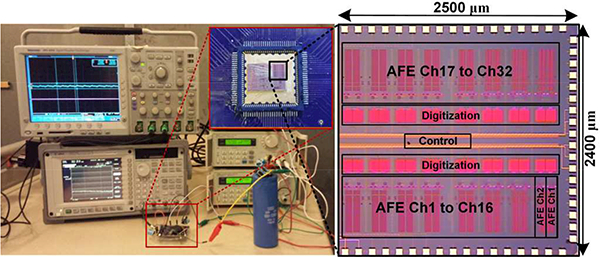
The experimental setup, die micrograph, and floorplan of the 32-ch proof-of-concept prototype AFE, including the control block.
Fig. 4.
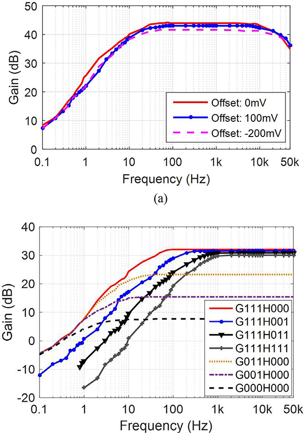
The measured AC responses of (a) the LNA, and (b) the VGA.
The VGA block can independently change the low cut-off frequency of the HPF from 1 Hz to 400 Hz (Digital bits: expressed as. H000-H111) and the midband gain from 7.6 dB to 32 dB (Digital bit: G000-G111). The LNA and VGA consume 11 μΑ and 2.1 μΑ from a 1 V supply, respectively. The power supply rejection ration (PSRR) is measured 41 dB at 1 kHz, and the input impedance of each LNA is ~61 ΜΩ at 1 kHz.
The noise spectral densities of the AFE for m = 1,4, and 16 are shown in Fig. 5a with their input referred transient background noise wavefonns in Fig. 5b. An additional MUX network is needed at the input for re-wiring and combining the desired input channels. In this prototype, however, we re-wired the inputs at the board-level to demonstrate and verity the effect of averaging. The AFE input-referred noise RMS for 1, 4, and 16 channels in parallel are 3.0 μVrms. 1.8 μVrms. and 1.1 μVrms in the 10 Hz to 17 kHz frequency range, respectively. According to (2), we anticipate the input referred noise to drop by a factor of 2 when increasing m by a factor of 4. Measurements, however, indicate lower factors of 1.64 and 1.67, respectively. This could be because the noise in each AFE channel is not entirely random and uncorrelated. Common noise sources, such as 60 Hz powerline interference or noise from the digital block, which appear on all AFE channels, cannot be reduced by averaging. Moreover, the input impedance at 1 kHz is inversely proportional to m. and decreases from 61 ΜΩ to 3.8 ΜΩ in 16-ch averaging, which results in slightly higher attenuation of the input signal, depending on the interconnect and electrode electrolyte impedances. The measured total harmonic distortion (THD) at 1 kHz and 1 mVnns input is 0.8% and the linear range of the input signal is up to 2.2 mVpp. The LNA shows almost constant gain of 43 dB from 0.32 V to 0.63 V.
Fig. 5.
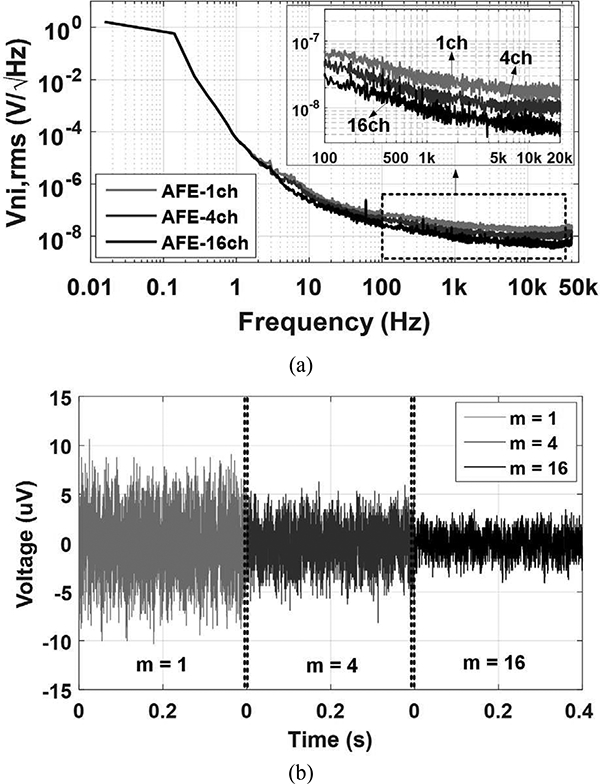
(a) The measured noise spectrums of the prototype AFE for m = 1, 4, and 16. (b) Measured transient background input referred noise waveforms.
Table II benchmarks specifications of the proof-of-concept AFE prototype with adaptive averaging against recently reported state-of-art biomedical AFEs for CNS and PNS applications. The proposed AFE demonstrates superior input impedance (ZIN) with very good input referred noise and NEF, while other parameters are still competitive. A key advantage of the proposed AFE is that it can flexibly disconnect channels with no good input signal and combine their AFE electronics with other LNAs in situ to improve the SNR of the channels with viable or more important recording capability over time.
Table II.
Benchmarking of the Proposed .Adaptive Averaging .Analog Front-End
| Parameter | This work | 2012 [6] | 2006 [4] | 2012*** [13] | 2016 [5] | 2015 [15] | 2016 [9] |
|---|---|---|---|---|---|---|---|
| VDD (V) | 1 | 1 | 5 | 0.5 | 0.2/0.8 | 1 | 3.3** |
| IAmp(μA) | 11/44/176 | 12.1 | 260 | 60 | 1.6/0.25 | 2.8 | 271 |
| LNA Gain (dB) | 44 | 40 | 40.8* | 32* | 50 | 52.1 | 39.3 or 58.4 |
| Bandwidth (Hz) | 20–15k | 0.025–7.2k | 310–3.3k | 300–10k | 0.5–670 | 1–8.2k | 0.1 −20k |
| I.R. Noise (μVrms) | 3.0/1.8/1.1 (m=1.4,16) | 2.2 | 0.29 | 4.9 | 0.94 | 4.13 | 0.63–1.5 |
| NEF | 2.95/3.54/4.32 | 2.9 | 4.3 | 5.99 | 2.1 | 2.93 | 3.5 |
| NEF2 ·DD | 8.68/12.5/18.7 | 8.4 | 92.45 | 17.96 | 1.6 | 8.58 | 40.4 |
| PSRR (dB) | 41 | 85 | 42 | 64 | 74 | 78 | NA |
| ZIN (@ 1 kHz (MΩ) | 61/15/3.8 | 4 | ~0.015** | NA | NA | ~20** | NA |
| .Area (mm2) | 0.07/0.28/1.12 | 0.072 | 12 | 0.013 | 0.32** | 0.042 | 0.51 |
| DC rejection | DC-coupled (−0.2V~0.1V) |
AC-coupled | NA | DC-coupled (±0.05V) |
AC-coupled | AC-coupled | AC-coupled |
| Application | CNS/PNS | CNS/PNS | PNS | CNS | EEG | CNS | CNS/PNS |
| Technology (nm) | 1.30 CMOS | 1.30 CMOS | 800 BiCMOS | 65 CMOS | 1 80 CMOS | 65 CMOS | 350 CMOS |
Open-loop
Estimated
Including digitization for offset rejection
The functionality of the AFE prototype was verified by playing attenuated pre-recorded spike wavefonns, which contained ~10 mVpp spikes plus 4 Hz sine local field potential (LFP) in the background. The signal was applied to the LNA input through −50 dB attenuation to generate spikes in tens of μVpp range. Fig. 6 shows the AFE input and output transient wavefonns, in which around t= 1.6 s, the control unit changes m from 16 to 1 in order to show the difference in SNR. The individual spikes are extracted in these wavefonns based on a threshold-based algorithm, and the SNR is calculated as [16],
| 6 |
Fig. 6.
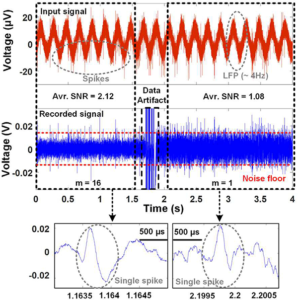
The attenuated pre-recorded original spike signal (Top) and recorded transient AFE output signal (Bottom) with transient adaptive noise variation from m = 16 to 1 for SNR comparison.
where Vi is the peak of an individual spike, and σ represents the standard deviation of the background noise. These measurements show that the average SNR is improved from 1.08 to 2.12 when m is changed from 1 to 16, thanks to the adaptive averaging technique. The pre-recorded spike signals applied to the LNA already have background noise and low frequency interference, which in this case mimic the electrode tissue interference and unwanted LFPs that should be filtered out to extract the spikes. Moreover, it should be noted that the input impedance at 1 kHz is inversely proportional to m. which results in slightly higher attenuation of the input signal depending on the electrode-electrolyte impedance. Therefore, the measured SNR shows 1.96 times improvement instead of 2.72 times, measured from the noise measurement in Fig. 5.
IV. Conclusions
An integrated adaptive averaging AFE architecture has been proposed for applications in which input referred noise need to be adjusted based on input signal conditions, such as recording from visceral neural networks. The proposed AFE is equipped with DC-coupled doubled-gm LNA to increase the NEF while maintaining high input impedance in a structure without AC-coupling capacitors or chopper modulation. The proposed architecture provides higher SNR particularly for multichannel recording from CNS and PNS with flexibility to dedicate the AFE resources to input channels with the most viable and information-rich input signals in various neuroprosthetic or electrophysiology recording applications.
Acknowledgments
This work was supported in part by the National Institutes of Health under grant R21EB018561 and National Science Foundation grant ECCS-1408318.
References
- [1].del Valle J and Navarro X, “Interfaces with the peripheral nerve for the control of neuroprostheses,” Int. Rev. Neurobiol, vol. 109, pp. 63–83, 2013. [DOI] [PubMed] [Google Scholar]
- [2].Navarro X et al. , “A critical review of interfaces with the peripheral nervous system for the control of neuroprostheses and hybrid bionic systems,” J. Peripher. Nerv. Syst, vol. 10, pp. 229–258, 2005. [DOI] [PubMed] [Google Scholar]
- [3].Chandrakumar H and Markovic D, “A simple area-efficient ripple-rejection technique for chopped biosignal amplifiers,” IEEE Trans. Cir. Syst. II, Express Briefs, vol. 62, no. 2, pp. 189–193, February 2015. [Google Scholar]
- [4].Rieger R, et al. , “Very Low-Noise ENG Amplifier System Using CMOS Technology,” IEEE Trans. Neural Systems Rehab. Eng, vol. 14, no. 4, pp. 427–437, December 2006. [DOI] [PubMed] [Google Scholar]
- [5].Yaul FM and Chandrakasan AP, “A sub-uW 36nV/√Hz chopper amplifier for sensors using a noise-efficient inverter-based 0.2V-supply input stage,” IEEE Inti. Solid-State Cir. Conf, pp. 94–95, February 2016. [Google Scholar]
- [6].Zhang F, Holleman J, and Otis BP, “Design of ultra-low power biopotential amplifiers for biosignal acquisition applications,” IEEE Trans. Biomed. Circuits Syst, vol. 6, no. 4, pp. 344–355, August 2012. [DOI] [PubMed] [Google Scholar]
- [7].Dweiri YM, et al. , “Ultra-low noise miniaturized neural amplifier with hardware averaging,” J. Neural Eng, vol. 12, pp. 1–10, June 2015. [DOI] [PubMed] [Google Scholar]
- [8].Wu F, et al. , “A multi-shank silk-backed parylene neural probe for reliable chronic recording,” Solid-State Sensors, Actuators and Microsystems Conference, pp. 888–891, 2013. [Google Scholar]
- [9].Cota OF, et al. , “In vivo characterization of a versatile 8-channel digital biopotential recording system with sub-μVrms input noise,” IEEE conference of EMBS, pp. 6311–6314, August 2016. [DOI] [PubMed] [Google Scholar]
- [10].Simeral J, et al. , “Neural control of cursor trajectory and click by a human with tetraplegia 1000 days after implant of an intracortical microelectrode array,” J. Neural Eng, vol. 8, p. 025–027., 2011. [DOI] [PMC free article] [PubMed] [Google Scholar]
- [11].Harrison RR and Charles C, “A low-power, low-noise CMOS amplifier for neural recording applications,” IEEE J. Solid-State Circuits, vol. 38, no. 6, pp. 958–965, June 2003. [Google Scholar]
- [12].Bagheri A, et al. , “Low-frequency noise and offset rejection in DC-coupled neural amplifiers: a review and digitally-assisted design tutorial,” IEEE Trans. Biomed. Circuits Syst, vol. 11, no. 1, pp. 161–176, February 2017. [DOI] [PubMed] [Google Scholar]
- [13].Muller R, Gambini S, and Rabaey JM, “A 0.013mm2 5μW DC-coupled neural signal acquisition IC with 0.5 V supply,” IEEE J. Solid-State Circuits, vol. 47, no. 1, pp. 232–243, January 2012. [Google Scholar]
- [14].Gosselin B, Sawan M, and Chapman CA, “A low-power integrated bioamplifier with active low-frequency suppression,” IEEE Trans. Biomed. Circuits Syst, vol. 1, no. 3, pp. 184–192, September 2007. [DOI] [PubMed] [Google Scholar]
- 15.[] Ng KA and Xu YP, “A multi-channel neural-recording amplifier system with 90dB CMRR employing CMOS-inverter-based OTAs with CMFB through supply rails in 65nm CMOS,” IEEE Intl. Solid-State Cir. Conf, pp. 206–207, February 2015. [Google Scholar]
- [16].Wu T, et al. , “A 16-channel nonparametric spike detection ASIC based on EC-PC decomposition,” IEEE Trans. Biomed. Circuits Syst, vol. 10, no. 1, pp. 3–16, February 2016. [DOI] [PubMed] [Google Scholar]
- [17].Han D, et al. , “A 0.45 V 100-channel neural-recording IC with sub-μ W/channel consumption in 0.18 CMOS,” IEEE Intl. Solid-State Cir. Conf pp. 290–291, February 2013. [DOI] [PubMed] [Google Scholar]


