Abstract
Novel electrospun polyacrylonitrile (PAN) nanofibrous membranes were prepared by using heat‐press lamination under various conditions. The air permeability and the burst‐pressure tests were run to select the membranes for point‐of‐use air and water cleaning. Membrane characterization was performed by using scanning electron microscopy, contact angle, and average pore size measurements. Selected membranes were used for both air dust filtration and cross‐flow water filtration tests. Air dust filter results indicated that electrospun PAN nanofibrous membranes showed very high air‐dust filtration efficiency of more than 99.99 % in between PM0.3 and PM2.5, whereas cross‐flow filtration test showed very high water permeability over 600 L/(m2hbar) after 6 h of operation. Combining their excellent efficiency and water permeability, these membranes offer an ideal solution to filter both air and water pollutants.
Keywords: air filtration, lamination, nanofiber, polyacrylonitrile, water filtration
1. Introduction
Water and air pollution are increasing concern all over the world as a risk of human health.1, 2, 3 Air pollution can cause asthma, skin irritation, nausea, cancer, brain damage, birth defects, respiratory and heart problems due to gaseous pollutants and particulate matter (PM).4, 5, 6, 7, 8 Based on inhalable particle size, PM is classified into coarse (2.5–10 μm), fine (0.1–2.5 μm) and ultrafine (<0.1 μm).9 Exposure to elevated PM levels over the long term can reduce life expectancy by a few years while short‐term exposure contributes to acute cardiovascular morbidity and mortality.8 Under this condition, an efficient air filter is demanded to capture of air pollutants in different sizes. Textile based high‐efficiency particulate air (HEPA) and ultra‐low particulate air (ULPA) filters can capture very small PM with a filtration efficiency over than 99.90 %.9 Fibrous materials that have fiber diameter about a few micrometers with porosity around 80–90 % can easily remove sub‐micrometer and micrometer particles from air and water with a high efficiency. Beside the air pollution, water pollution is another issue that needs an emergency solution for the current and future life. The availability of freshwater resources has been reduced due to a growing population. As a result of population growth, the amount of water consumption and the number of manufacturing and industrial production have been increased. The industries, such as chemical, paper, beverage, automotive, food, agriculture, power generation, textiles, and garments consume tons of water daily. By 2030, it is expected that the demand for water supply will exceed about 40 % of current supply.10 Before reuse or releasing the used water directly to nature, it is necessary to clean the water from contaminations. Membrane technology is one of the effective and successful methods to compete with conventional separation process for the treatment of wastewater due to their low cost, energy‐efficiency, compactness, high permeability, and high selectivity and easy‐to‐operate properties. In principle, the membrane acts as a semi‐permeable barrier that separates two distinct phases usually under a driving force. For an effective separation and high throughput, the membrane should have a proper pore size with a highly porous structure.
Nanofibrous webs have a large surface area to volume, high porosity, tight pore size and high permeability that make them an appropriate candidate for filtration applications. Therefore, nanofibers have received increased attention in water and air domain applications. The first commercialized application of electrospun nanofibers was in air filters.11 Despite the high permeability and tight pore size, the application of nanofiber webs in the water domain area is limited. The main reason is the mechanical weakness of single layer nanofiber web. In the application of membranes, the nanofiber webs require additional supporting layer or additives to provide strength. Several methods have been reported to develop mechanical strength of the nanofiber webs. Blending of polymers,12 dip‐coating,13 or polymer and an additive such as epoxy14 or inorganics15,16 were suggested as solutions for the improvement of the strength. However, these methods require time and chemicals which is costly. Recently, Wirth et al.17 reported ultrasonic welding of polyacrylonitrile (PAN) nanofiber mats without destruction of the mat morphology. Various welding patterns were used and their effects on adhesion forces between both joined nanofiber mats and different failure mechanisms have been investigated. The results indicated that some welding patterns enabled bonding stronger than the mats themselves. However, this method still needs to optimize based on materials and the pattern of welding equipment. Other attempts to prevent damage of nanofiber webs have been done as nanofiber‐coated yarn.18, 19, 20, 21 A macroscopic size random yarn has been used as core and nanofiber layer was covered around. To form a textile structure, it is necessary to use knitting or weaving technology. An external yarn is necessary to cover for the protection of the open surface of the nanofiber layer before knitting or weaving which makes the process costly. In the various study, the nanofibers webs are combined to a support either like layer to layer or sandwiched structure between different layers.22, 23, 24, 25, 26, 27, 28, 29, 30 Jiricek31,32 and Yalcinkaya et al.24,33 used a bi‐component polyethylene (PE) /polypropylene (PP) spun bond as a supporting layer for nanofiber layers. Heat‐press technique was applied using a fusing machine for the lamination process. The polyvinylidene fluoride (PVDF) and polyamide‐6 (PA‐6) nanofiber layers were adhered on the outer surface of the bi‐component due to the low melting point of PE. The resultant multilayer nanofibrous membranes were used for water distillation and desalination. In the previous work,26,30 the PVDF nanofibrous membranes have been prepared using heat‐press technique under various conditions. Results indicated that PVDF nanofibers are suitable as water and air filters.
In this work, polyacrylonitrile (PAN) nanofiber web was prepared using needle‐free wire electrospinning industrial production method. PAN is easy to electrospun into nanofiber and has thermal stability, tolerance to most solvents, and commercial availability.34,35 The mechanical strength of the prepared electrospun web was improved by lamination with a supporting layer and adhesive web. The lamination conditions, such as temperature, duration of heat‐press and force of the press have been investigated. The air permeability and burst pressure tests were run to determine membranes for air and water filtration test. The ultimate goal of this work is to introduce electrospun PAN nanofibrous membranes that prepared by industrial production method as air and water filter. So far, there has been no deep work reported for the lamination of PAN nanofibers using heat press under various lamination condition and then apply for both air and water filtration.
2. Results and Discussion
2.1. Selection of the Membranes
PAN nanofiber layer was laminated under various conditions and 18 types of membranes were prepared. The selection of the filter membranes has been done based on their air permeability and bursting pressure as shown in Figure 1. Figure 1 is divided into 6 pieces according to the temperature and duration of lamination. In each piece, there are three values which show the lamination force in the order of 40, 50, and 100 kN, respectively. Membranes were selected according to high bursting pressure and the air permeability. Hence, there is no previous work dealing with optimum air permeability and the bursting pressure of membranes, we decided to select the membranes which had higher air permeability and bursting pressure. In this case, a line was drawn in Figure 1, on 4 Lm−2s−1 air permeability and 195 kN bursting pressure. The selective membranes were marked with a green square.
Figure 1.
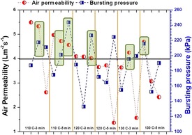
Effect of lamination conditions on air permeability and the delamination strength of various PAN membranes.
Based on the Figure 1, (a) the air permeability of the membranes decreased with increased temperature, applied lamination force, and lamination duration, (b) since, bursting pressure depends on both adhesion properties of the hybrid materials and the conditions of lamination, it is difficult to explain the relationship between bursting pressure and the lamination condition.
It is possible to say that, lamination force had an effect on bursting pressure, such as when the applied pressure increased the bursting pressure was increased. However, under high heat (130 °C) and long lamination period (5 min), the adhesive web and nanofiber layer lost its strength and resulted in low resistance to delamination. Results also suggested that the air permeability of the membrane was in direct proportion to the applied force of the lamination process. Higher applied force means, melted adhesive can penetrate through the pores of the nanofiber layer and reduce the porosity of the membrane. The melted adhesive covered the surface of the nanofiber layer. As a result, a non‐fibrous, film structure can form on the surface as shown in Figure 2. The region of film adhesive on the surface of the membrane blocked the pores. Even though these regions are not demanded, these regions provide better adhesion between the support and nanofiber layer. To prepare an optimal material, it should be considered both permeability and the bursting resistance of the membranes.
Figure 2.
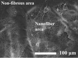
The surface of the PAN nanofibrous membrane after the lamination process.
The air permeability is an important criterion for the membrane permittivity, especially for the air filters. On the other hand, bursting pressure shows the necessary minimum pressure to destroy or to separate nanofiber layer from the supporting materials. In this case, selection high air permeability and the bursting pressure are demanded. Based on the results in Figure 1, only 5 membranes showed higher air permeability and at the same time higher bursting pressure. These membranes are; PAN_110_50_3, PAN_110_50_5, PAN_110_100_5, PAN_120_100_3, PAN_130_50_3, PAN_130_40_5.
2.2. Surface Characterization
The SEM images of the samples are taken and shown as in Figure 3. Comparing the diameter of the fiber, SEM images showed that after the lamination process, the fiber diameter increased almost 75 % more due to the structural change of PAN under heat and pressure. Unlike the literature finding,36 hot press process affected the fiber diameter of PAN nanofibers. Sabantina et al.37 observed that the diameter of the PAN nanofiber on the polypropylene substrate increased while the PAN nanofiber diameter stayed constant on aluminum foil after stabilization under 280 °C.
Figure 3.
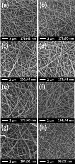
SEM images of a) PAN_110_50_3, b) PAN_110_50_5, c) PAN_110_100_5, d) PAN_120_100_3, e) PAN_130_50_3, f) PAN_130_40_5, g) PAN_130_100_5, and h) PAN nanofiber before lamination process.
Under the force and applied temperature of the lamination, the fibers were getting flattened. Increasing applied temperature and the force caused fusion and bending. As a result, fiber diameter increased. Figure 3 (g) was taken to observe the fiber diameter under the highest force (100 kN), temperature (130 °C) and duration (5 min) of the lamination. Apparently, PAN_130_100_5 had the highest fiber diameter among the others. In the literature, it was found that applying heat treatment increased the fusion at interfiber contact points which increased the mechanical strength of the electrospun membranes.38,39 The mechanical strength of the PAN nanofiber increased 760 times after hot‐press process.36 However, excessive lamination temperature, force, and duration may cause low mechanical strength and deterioration of the mechanical property.
Water contact angle of the membranes was measured and shown in Figure 4. The contact angle results indicate that membranes are hydrophobic which is not an advantage for liquid separation. Membranes which has a water contact angle greater than or equal to 90° is counted as hydrophobic membranes.22 It was found that the hydrophobic PVDF became hydrophilic after the lamination process.30 Unlike the PVDF membranes, the lamination conditions at given range did not change the wettability of the membranes. The previous work showed that neat PAN nanofiber has a contact angle around 70° under the lamination condition at a temperature of 135 °C and 50 kN pressure for 3 min.40 That might be the melted effect of adhesive web and the changing of the PAN structure under high temperature. In general, it is known that hydrophobic membranes tend to foul easier than hydrophilic ones. For this reason, a surface modification is required for the increase of the electrospun PAN membrane wettability. Previous works showed that the hydrophilic surface modification of electrospun PAN membrane with plasma treatment was not long lasting while additional chemical modification provided permeant wettability.40,41
Figure 4.
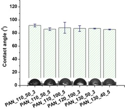
Water contact angle of the electrospun PAN membranes.
Membrane pore size is an important criterion for the selectivity and the permeability of the membrane. Pore size, size distribution, and porosity are parameters that directly influence the air permeability of the nanofiber web. Fiber diameter plays a major role in the pore size of the nanofiber layers.42, 43, 44 The average pore size according to the fiber diameter of the membranes is shown in Figure 5. The pore size and the fiber diameter of the membranes showed almost the same behavior. Pore size increased with fiber diameter. Li et al. showed that the pore size and pore size distribution of the polylactic acid (PLA) nanofiber membranes directly related to fiber diameter and area weight of the membrane.45 Herein, the area weight of the membranes was kept the same while fiber diameter slightly changed depends on the lamination condition. In that case, it can be assumed that only fiber diameter and the lamination conditions are strongly associated with the pore size of the membranes. The adhesive during lamination process is melting and can fill pores of the membranes which might cause a reduction in pore size and porosity of the membranes. A proper lamination condition has to be determined without losing the performance of the membranes.
Figure 5.
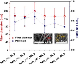
Pore size vs. fiber diameter of the electrospun PAN membranes.
2.3. Filtration Results
Air filtration test was run and the removal of the particles in between PM0.1 and PM2.5 has been measured. Non‐slip flow is the dominant mechanism for the high‐efficiency particulate air (HEPA) and ultra‐low particulate air (ULPA) filters. The problem of commercial HEPA and ULPA filters are that they can clog very easily due to the limited specific surface area.9,46 Since the fiber size of the nanofibers is small in the nm range, the slip‐flow mechanism becomes more important to disturb the airflow.47 As a result, the dust particles are collected to the surface not inside of the nanofiber layer which could improve the cleaning of the membranes.
The efficiency of the particle removal of the nanofibrous membranes is given in Figure 6. In all experiments, the superficial air velocity was 5 cm/s with a filter area 100 cm2.
Figure 6.
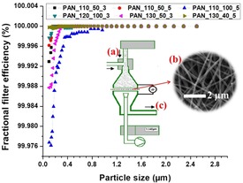
Filtration efficiency of the membranes against to various particle sizes and the schematic diagram of the filtration unit: a) dust particles, b) nanofibrous membrane, and c) filtered air.
Air filtration results indicated that all the membranes have superior filtration efficiency over than 99.97 % at various particle sizes. Among all membranes, PAN_130_40_5 showed highest filter efficiency (>99.999 %) for the PM0.1.
Zhao et al.48 prepared PAN nanofibers in various fiber diameters using lithium chloride salt (LiCl) at various concentrations. The air transmission resistance of the PAN membranes was measured to verify slip flow of air molecules from the surface of the nanofibers. The slip‐effect could be controlled by the fiber diameter at standard atmospheric condition. They found that the slip‐effect was gradually weakening with the reduction of fiber diameter. Their results indicated that PAN fibrous membranes with the optimized parameters showed very high PM2.5 purification efficiency of 99.09 %, low air resistance of 29.5 Pa, and long service life. In this work, since the fiber diameter of the membranes are almost equal after the lamination process, the lamination condition was the only effective parameter on the permeability of the membranes. To characterize the filter performance, quality factor (QF) was calculated. The QF of the membranes was calculated using the Eq. (1):48,49
| (1) |
where P is the pressure drop, and n is the filtration efficiency. The quality factor has been calculated for the PM0.1. The QF of PAN membranes are given in Figure 7. QF is directly proportional to filtration efficiency while was negatively proportional to the pressure drop. The higher the QF means the better the filter performance. Herein, both PAN 110_50_3 and PAN_130_40_5 showed the highest QF among the other membranes. The PAN 130_40_5 showed not only the better dust filtration efficiency, but also QF compared to other PAN membranes.
Figure 7.
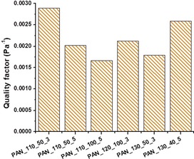
QF of various PAN nanofibrous membranes.
The results indicated that PAN nanofibrous membranes had high particle separation efficiency for coarse and fine particles. However, the air permeability of the PAN membranes was extremely low (lower than 6 Lm−2 s−1) which increase the pressure drop and low energy saving for long‐term use. In general, nanofiber webs itself have a very low‐pressure drop. After the lamination process, most probably the melted adhesive web filled to pores of nanofiber web and decreased the porosity of the membranes. As a result, the air permeability decreased. However, PAN membranes can be potentially employed as HEPA filter with high efficiency in clean air applications such as in airplanes, hospitals, and clean rooms.
The water permeability test was run using tap water. The tap water is not pure; it contains several minerals, inorganics, hormones, fluorine compounds, etc. that can cause membrane fouling. The water permeability test was run to proof whether the membranes were suitable for water treatment or not. The results are given in Figure 8. The results indicated that the permeability of the membranes was over than 4000 L/(m2 h bar). However, the permeability reduced gradually through the membrane in time due to several possible reasons such as concentration polarization and membrane fouling.26,50,51 After 3 h of operation, the membrane permeability reached to steady‐state. Among the all membranes, PAN_110_50_3, PAN_110_50_5 and PAN_120_100_3 showed the highest permeability (>1200 L/(m2 h bar)) after 6 h of operation. On the other hand, membranes that laminated at the highest temperature (130 °C) showed the lowest permeability which is almost half of other membranes (>600 L/(m2 h bar)). The results indicated lamination temperature had an influence on the water permeability of PAN nanofibrous membranes. It was found that heated PAN nanofibers over their glass temperature, the segmental mobility of the molecular chains and dipole‐dipole interaction of the nitrile groups increased. The nitrile groups started to release from their bound state. As a result, crystallization of the fiber improved.52, 53, 54 Herein, the temperature most probably affects the crystalline structure and pore size (Figure 5) of the PAN membranes which may reduce the water permeability. It was found that water absorption rate decreased with an increased crystallinity of the polymer.55, 56, 57
Figure 8.
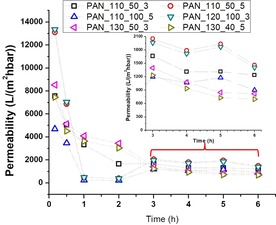
Water permeability of the various PAN nanofibrous membranes during 6 h.
It can be generalized that PAN nanofibrous membranes that laminated using heat‐press showed extremely high permeability compared to that literature58,59 which showed less than 400 L/(m2 h bar) for pure water permeation.
Hwang et al.60 compared three types of commercial membranes for crossflow microfiltration. The membranes were MF‐Millipore® (made of mixed cellulose esters), Durapore® (made of modified polyvinylidene difluoride) and Isopore® (made of bisphenol polycarbonate) membrane with the same mean pore size of 0.1 μm. The results indicated that Isopore membrane showed the highest flux rate (≈5×10⁵ L/(m2s)) compared to MF‐Millipore (≈4×10⁵ L/(m2s)) and Durapore (≈2×10⁵ L/(m2s)) membranes after 3000 second of operation time. The flux rates of the membranes in this work were changed in between 1×10⁵ L/(m2 s) (PAN_110_100_5) and 2×10⁵ L/(m2 s) (PAN_130_50_3) after 3600 seconds of operation time. The filtration test results indicated that PAN membranes are comparable with the commercial membranes without any post‐treatment.
The results indicate, PAN nanofibrous membranes that laminated under various condition showed enormous water permeability. Electrospun PAN nanofibrous membrane seems a good candidate for the treatment of wastewater. Comparable results were obtained in the literature using PVDF nanofibrous membranes.30 The PVDF nanofibrous membranes that were laminated under different condition using the same heat‐press system showed very high water permeability. It can be concluded that the heat‐press lamination system is suitable for the preparation of nanofibrous membranes for water treatment.
3. Conclusions
PAN nanofibers were laminated under various conditions and tested as air and liquid filtration in order to assay whether these laminated membranes are suitable for end use or not. The air permeability and the burst pressure tests determined the selective membranes according to their permeable structure and resistance to delamination. Selected membranes used for air and water filtration. The air filtration results showed the membranes had very high filtration efficiency (≥99.97) for PM0.1. However, the membranes showed very low air permeability due to adhesion method. The adhesive between the membrane and support melted and reduced the porosity of the membrane. The low air permeable membranes require more energy and which is costly. The air permeability problem can be overcome using different lamination technique. Conversely, PAN membranes showed very high water permeability (>600 L/(m2 h bar)) after 6 h of operation. Results indicate that electrospun PAN nanofibrous membranes laminated by heat‐press are more suitable for water domain application compared to air filtration. Hence, the aim of this work is the investigation of the lamination process and effect on air and water filtration, the self‐cleaning property and the surface modification of PAN membranes will be studied as future work.
Experimental Section
Preparation of Membranes
8 % wt. of PAN (150 kDa H‐polymer, Elmarco, Liberec, Czech Republic) was prepared in N, N‐dimethylacetamide (DMAc) and mixed over the night. The solvent was purchased from Penta s.r.o. (Prague, Czech Republic). The prepared solution was electrospun using needle‐free electrospinning equipment (Nanospider NS 8S1600U, Elmarco, Liberec, Czech Republic). The spinning conditions were determined as; +55 kV/‐−5 kV voltage with a distance between the electrodes was 188 mm. The humidity and the temperature were set as unchanged by using an air controlling unit as 20 % RH and 23 °C. A backing paper was used as collecting material for the nanofiber with a speed of 15 mm/min. The final density of the nanofiber web was 3 g/m2. The details of the electrospinning system and the spinning conditions were given in somewhere else.26
Prepared nanofiber webs were undergone to a lamination process to combine nanofibers onto a suitable substrate for filtration application. A co‐polyamide adhesive web (Protechnic, Cernay, France) was used between 100 g/m2 polyethylene terephthalate spun bond nonwoven supporting layer (Mogul Co. Ltd., Gaziantep, Turkey) and the PAN nanofiber to adhere layers. For this aim, heat‐press (hot‐press) equipment is used (Pracovni Stroje, Teplice, Czech Republic). Lamination condition was optimized by changing of applied heat, force and the duration of lamination time. Table 1 shows the lamination condition and the abbreviation of each sample. 18 samples were prepared and tested. The abbreviation of the samples was given according to the name of nanofiber_lamination temperature_lamination force_duration of lamination.
Table 1.
Preparation of nanofibrous membranes under various lamination conditions.
| Nanofiber | Temperature [°C] | Applied force [kN] | Time [min] | Abbreviation |
|---|---|---|---|---|
| PAN | 110 | 40 | 3 | PAN_110_40_3 |
| 50 | PAN_110_50_3 | |||
| 100 | PAN_110_100_3 | |||
| 40 | 5 | PAN_110_40_5 | ||
| 50 | PAN_110_50_5 | |||
| 100 | PAN_110_100_5 | |||
| 120 | 40 | 3 | PAN_120_40_3 | |
| 50 | PAN_120_50_3 | |||
| 100 | PAN_120_100_3 | |||
| 40 | 5 | PAN_120_40_5 | ||
| 50 | PAN_120_50_5 | |||
| 100 | PAN_120_100_5 | |||
| 130 | 40 | 3 | PAN_130_40_3 | |
| 50 | PAN_130_50_3 | |||
| 100 | PAN_130_100_3 | |||
| 40 | 5 | PAN_130_40_5 | ||
| 50 | PAN_130_50_5 | |||
| 100 | PAN_130_100_5 |
Characterization of the Membranes
Scanning electron microscope (SEM, Vega 3SB, Brno, Czech Republic) and Krüss Drop Shape Analyzer DS4 (Krüss GmbH, Hamburg, Germany) were used to determine both surface shape and contact angle of the samples. At least 50 measurements for fiber diameter and 5 measurements for the contact angle were done. The pore size of the samples was measured according to capillary flow porosimetry theory using a custom‐made device in our laboratory.
Burst‐pressure of the nanofiber layer from the supporting layer was measured by the device built in our laboratory.26 Using burst‐pressure, the minimum strength to burst nanofibrous membranes was measured.
Filtration tests
The air permeability of all multilayer nanofibrous membranes was tested using an SDL ATLAS Air Permeability Tester (@200 Pa and 20 cm2, South Carolina, US). At least three measurements were taken for each sample.
For air filtration, the particle filtration test for the selected membranes done was by MPF 1000 HEPA filtration device (PALAS GmbH, Karlsruhe, Germany) in between PM0.1 and PM2.5.
A cross‐flow filtration unit was built in our laboratory for the water filtration test as shown in Figure 9. The flux (F) and the permeability (k) of the selected membranes were calculated according to Eq. (2) and (2):
| (2) |
| (3) |
Figure 9.
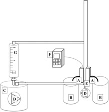
A cross‐flow unit: A) membrane cells, B) permeate, C) feed, D) pump, E) surface bubble cleaning, F) pressure controller, G) feed flow speed controller.
where A is the effective membrane area (m2), V is the total volume of the permeate (L), p is the transmembrane pressure (bar), and t is the filtration time (h).
Conflict of interest
The authors declare no conflict of interest.
Supporting information
As a service to our authors and readers, this journal provides supporting information supplied by the authors. Such materials are peer reviewed and may be re‐organized for online delivery, but are not copy‐edited or typeset. Technical support issues arising from supporting information (other than missing files) should be addressed to the authors.
Supplementary
Acknowledgements
This work was supported by the Ministry of Education, Youth and Sports of the Czech Republic and the European Union – European Structural and Investment Funds in the frames of Operational Programme Research, Development and Education – project Hybrid Materials for Hierarchical Structures (HyHi, Reg. No. CZ.02.1.01/0.0/0.0/16_019/0000843).
R. Roche, F. Yalcinkaya, ChemistryOpen 2019, 8, 97.
References
- 1. Worthington M. J. H., Kucera R. L., Albuquerque I. S., Gibson C. T., Sibley A., Slattery A. D., Campbell J. A., Alboaiji S. F. K., Muller K. A., Young J., Chem. Eur. J. 2017, 23, 16219–16230. [DOI] [PMC free article] [PubMed] [Google Scholar]
- 2. Nomura A., Jones C. W., Chem. Eur. J. 2014, 20, 6381–6390. [DOI] [PubMed] [Google Scholar]
- 3. Zhang R., Yu Z., Wang L., Shen Q., Hou X., Guo X., Wang J., Zhu X., Yao Y., Chem. Eur. J. 2017, 23, 13696–13703. [DOI] [PubMed] [Google Scholar]
- 4. Ho A. F. W., Wah W., Earnest A., Ng Y. Y., Xie Z., Shahidah N., Yap S., Pek P. P., Liu N., Lam S. S. W., Int. J. Cardiol. 2018, 271, 352–358. [DOI] [PubMed] [Google Scholar]
- 5.W. H. Organization, “Ambient (outdoor) air quality and health,” can be found under http://www.who.int/en/news-room/fact-sheets/detail/ambient-(outdoor)-air-quality-and-health, n.d.
- 6. Brook R. D., Rajagopalan S., Pope C. A., Brook J. R., Bhatnagar A., Diez-Roux A. V., Holguin F., Hong Y., Luepker R. V., Mittleman M. A., Circulation 2010, 121, 2331–2378. [DOI] [PubMed] [Google Scholar]
- 7. Pope C. A., Burnett R. T., Thurston G. D., Thun M. J., Calle E. E., Krewski D., Godleski J. J., Circulation 2004, 109, 71–77. [DOI] [PubMed] [Google Scholar]
- 8. Markevych I., Tesch F., Datzmann T., Romanos M., Schmitt J., Heinrich J., Sci. Total Environ. 2018, 642, 1362–1368. [DOI] [PubMed] [Google Scholar]
- 9. Kadam V. V, Wang L., Padhye R., J. Ind. Text. 2018, 47, 2253–2280. [Google Scholar]
- 10. Mahdi M., Shirazi A., Kargari A., Ramakrishna S., Doyle J., Rajendrian M., Babu P. Ramesh, J. Membr. Sci. Res. 2017, 3, 209–227. [Google Scholar]
- 11.D. Groitzsch, E. Fahrbach, Microporous Multilayer Nonwoven Material for Medical Applications, 1985, US4618524A.
- 12. Yalcinkaya F., Arab. J. Chem. 2016, DOI 10.1016/j.arabjc.2016.12.012. [Google Scholar]
- 13. Charles L. F., Shaw M. T., Olson J. R., Wei M., J. Mater. Sci. Mater. Med. 2010, 21, 1845–1854. [DOI] [PubMed] [Google Scholar]
- 14. Jahanbaani A. R., Behzad T., Borhani S., Darvanjooghi M. H. K., Fibers Polym. 2016, 17, 1438–1448. [Google Scholar]
- 15. Charles L. E., Kramer E. R., Shaw M. T., Olson J. R., Wei M., J. Mech. Behav. Biomed. Mater. 2012, 17, 269–277. [DOI] [PubMed] [Google Scholar]
- 16. Liu R., Ma L., Mei J., Huang S., Yang S., Li E., Yuan G., Chem. Eur. J. 2017, 23, 2610–2618. [DOI] [PubMed] [Google Scholar]
- 17. Wirth E., Sabantina L., Weber M., Finsterbusch K., Ehrmann A., Nanomaterials 2018, 8, 746. [DOI] [PMC free article] [PubMed] [Google Scholar]
- 18.F. Yalcinkaya, M. Komarek, D. Lubasova, F. Sanetrnik, J. Maryska, Nanocon 2014, 6th Int. Conf 2015.
- 19. Malašauskienė J., Milašius R., J. Nanomater. 2013, 2013, 1–6. [Google Scholar]
- 20. Yalcinkaya F., Komarek M., Lubasova D., Sanetrnik F., Maryska J., J. Nanomater. 2016, 2016, 1–7. [Google Scholar]
- 21. Liu C. K., He H. J., Sun R. J., Feng Y., Wang Q. shi, Mater. Des. 2016, 112, 456–461. [Google Scholar]
- 22. Yalcinkaya F., Yalcinkaya B., Hruza J., Hrabak P., Sci. Adv. Mater. 2016, 9, 747–757. [Google Scholar]
- 23. Kanafchian M., Valizadeh M., Haghi A. K., Korean J. Chem. Eng. 2011, 28, 445–448. [Google Scholar]
- 24. Yalcinkaya B., Yalcinkaya F., Chaloupek J., J. Nanomater. 2016, 2016, 1–12. [Google Scholar]
- 25. Yoon B., Lee S., Fibers Polym. 2011, 12, 57–64. [Google Scholar]
- 26. Yalcinkaya F., Hruza J., Nanomaterials 2018, 8, 272. [DOI] [PMC free article] [PubMed] [Google Scholar]
- 27. Liu W., Wang S., Xiao M., Han D., Meng Y., Chem. Commun. 2012, 48, 3415–3417. [DOI] [PubMed] [Google Scholar]
- 28. Yalcinkaya F., Yalcinkaya B., Hruza J., Hrabak P., Maryska J., in NANOCON 2016 - Conf. Proceedings, 8th Int. Conf. Nanomater. - Res. Appl., TANGER, Brno, 2016. [Google Scholar]
- 29. Valipour P., Babaahmadi V., Nasouri K., Adv. Polym. Technol. 2014, 33, DOI 10.1002/adv.21440. [Google Scholar]
- 30. Roche R., Yalcinkaya F., Nanomaterials 2018, 8, 771. [DOI] [PMC free article] [PubMed] [Google Scholar]
- 31. Jiříček T., Komárek M., Chaloupek J., Lederer T., Desalin. Water Treat. 2017, 73, 249–255. [Google Scholar]
- 32.T. Jiříček, M. Komárek, J. Chaloupek, T. Lederer, Komá, M. Rek, J. Chaloupek, T. Lederer, J. Nanomater 2016, 2016, 1–7.
- 33. Yalcinkaya B., Yalcinkaya F., Chaloupek J., Desalin. Water Treat. 2017, 59, 19–30. [Google Scholar]
- 34. Mei Y., Yao C., Fan K., Li X., J. Membr. Sci. 2012, 417–418, 20–27. [Google Scholar]
- 35. Yalcinkaya F., Siekierka A., Bryjak M., Polymers (Basel). 2017, 9, 679. [DOI] [PMC free article] [PubMed] [Google Scholar]
- 36. Ali A. A., Rutledge G. C., J. Mater. Process. Technol. 2009, 209, 4617–4620. [Google Scholar]
- 37. Sabantina L., Rodríguez-Cano M. Á., Klöcker M., García-Mateos F. J., Ternero-Hidalgo J. J., Mamun Al, Beermann F., Schwakenberg M., Voigt A. L., Rodríguez-Mirasol J., Polymers (Basel). 2018, 10, 735. [DOI] [PMC free article] [PubMed] [Google Scholar]
- 38. Ma Z., Kotaki M., Ramakrishna S., J. Membr. Sci. 2005, 265, 115–123. [Google Scholar]
- 39. Zhang L., Liu L.-G., Pan F.-L., Wang D.-F., Pan Z.-J., J. Eng. Fibers Fabr. 2012, 7, 7–16. [Google Scholar]
- 40. Yalcinkaya F., J. Appl. Polym. Sci. 2018, 135, 46751. [Google Scholar]
- 41. Yalcinkaya F., Siekierka A., Bryjak M., RSC Adv. 2017, 7, 56704–56712. [Google Scholar]
- 42. Abuzade R. A., Zadhoush A., Gharehaghaji A. A., J. Appl. Polym. Sci. 2012, 126, 232–243. [Google Scholar]
- 43. Eichhorn S. J., Sampson W. W., J. R. Soc. Interface 2010, 7, 641–649. [DOI] [PMC free article] [PubMed] [Google Scholar]
- 44. Krifa M., Yuan W., Text. Res. J. 2016, 86, 1294–1306. [Google Scholar]
- 45. Li D., Frey M. W., Joo Y. L., J. Membr. Sci. 2006, 286, 104–114. [Google Scholar]
- 46. Podgórski A., Bałazy A., Gradoń L., Chem. Eng. Sci. 2006, 61, 6804–6815. [Google Scholar]
- 47. Sundarrajan S., Tan K. Luck, Lim S. Huat, Ramakrishna S., Procedia Eng. 2014, 75, 159–163. [Google Scholar]
- 48. Zhao X., Wang S., Yin X., Yu J., Ding B., Sci. Rep. 2016, 6, 35472. [DOI] [PMC free article] [PubMed] [Google Scholar]
- 49. Jiang Z., Zhang H., Zhu M., Lv D., Yao J., Xiong R., Huang C., J. Appl. Polym. Sci. 2018, 135, 45766. [Google Scholar]
- 50. Aimar P., Meireles M., Bacchin P., Sanchez V., in Membr. Process. Sep. Purif., Springer Netherlands, Dordrecht, 1994, pp. 27–57. [Google Scholar]
- 51. Rezaei H., Ashtiani F. Z., Fouladitajar A., Braz. J. Chem. Eng. 2014, 31, 503–518. [Google Scholar]
- 52. Sadrjahani M., Ravandi S. A. Hosseini, Fibers Polym. 2013, 14, 1276–1282. [Google Scholar]
- 53. Masson J. C., Acrylic Fiber Technology and Applications, M. Dekker, 1995. [Google Scholar]
- 54. Gupta A. K., Maiti A. K., J. Appl. Polym. Sci. 1982, 27, 2409–2416. [Google Scholar]
- 55. Lin Y., Zhong W., Shen L., Xu P., Du Q., J. Macromol. Sci. Phys. 2005, 44 B, 161–175. [Google Scholar]
- 56. Negoro T., Thodsaratpreeyakul W., Takada Y., Thumsorn S., Inoya H., Hamada H., in Energy Procedia, Elsevier, 2016, pp. 323–327. [Google Scholar]
- 57. Auckland D. W., Cooper R., in Conf. Electr. Insul. Dielectr. Phenom. - Annu. Rep. 1974, IEEE, 1974, pp. 71–79. [Google Scholar]
- 58. Scharnagl N., Buschatz H., Desalination 2001, 139, 191–198. [Google Scholar]
- 59. Xu Y., Wei Q., Functional Nanofibers and Their Applications, Woodhead Publishing, 2012. [Google Scholar]
- 60. Hwang K. J., Lin T. T., J. Membr. Sci. 2002, 199, 41–52. [Google Scholar]
Associated Data
This section collects any data citations, data availability statements, or supplementary materials included in this article.
Supplementary Materials
As a service to our authors and readers, this journal provides supporting information supplied by the authors. Such materials are peer reviewed and may be re‐organized for online delivery, but are not copy‐edited or typeset. Technical support issues arising from supporting information (other than missing files) should be addressed to the authors.
Supplementary


