Recently, various bottom-up methods have been developed to fabricate nano- and microscale devices in microelectronics, optics, actuators, and sensors.1 Introduction of biological self-assembly of nanometer-sized building blocks is expected to accomplish the bottom-up fabrications in a more reproducible, efficient, and economic manner.2 Recently, carbon nanotubes were also assembled on regions coated with the polar chemical groups in large scale.3 However, multiple types of nano-building blocks, such as metal nanowires and semiconductor nanowires, are necessary to be placed at specific locations on surfaces selectively with high precision and reproducibility for more complex nanometer-scale device assemblies.4 Biological molecular recognition such as antibody–antigen bindings may be suitable to apply in the building-block assembly since nature always assembles materials with complex functions and structures at room temperature reproducibly.5 Our approach is to immobilize antibody-coated nanotubes at specific complementary binding positions patterned on surfaces. Because a variety of antibodies and antigens are available, proper choices of antibodies and antigens will enable one to assemble multiple types of nanotubes incorporating different antibodies at the antigen-patterned areas in a single process.
Previously, antibody nanotubes were synthesized by coating antibodies onto template nanotubes self-assembled from bolaamphiphile peptide monomers via hydrogen bonding, and one kind of antibody nanotube was examined for attachment onto a patterned complementary antigen area to form the nanotube array.5c However, to test the feasibility of antibody nanotubes for real applications in device fabrications by assembling them into more complex configurations, it is necessary to place multiple types of antibody nanotubes onto their respective complementary binding areas. To prove this hypothesis, two types of nanotubes coated with different antibodies were anchored selectively onto their complementary antigen areas, patterned by tips of atomic force microscope (AFM).
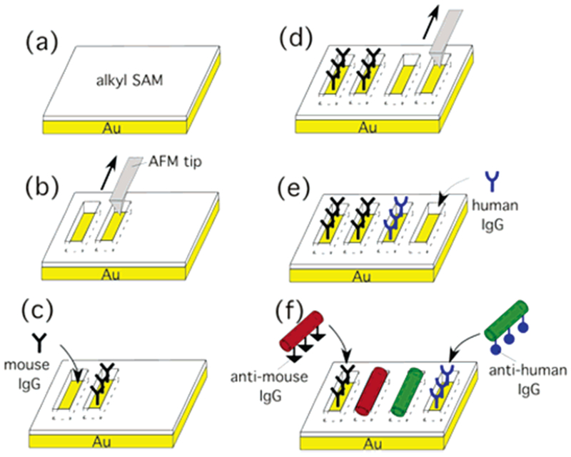
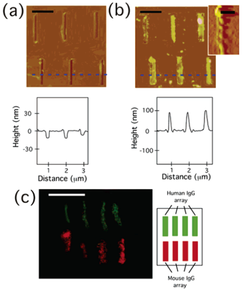
To demonstrate the molecular recognition-driven immobilization of two different types of antibody nanotubes onto the complementary antigen arrays, we designed the fabrication steps, as shown in Figure 1. After 1-octadecanethiol (0.01 mM) was self-assembled on Au substrates in 99% ethanol at room temperature for 24 h (Figure 1a), a series of trenches (150 nm × 1 μm) were etched by shaving the alkylthiol SAM with a Si3N4 tip (Veeco Metrology) of AFM (Nanoscope IIIa and MultiMode microscope, Digital Instruments), as shown in Figure 1b. The array of these trenches, whose bottom surfaces were gold, was patterned by using a customized Nanoscript software (Veeco Metrology). In Figure 2a (top), these trenches appear in a darker contrast as compared to the unshaved SAM surface, which indicates the heights of trenches are lower than the SAM. The section analysis of the trenches in Figure 2a (bottom) shows that the average depth of all trenches is −10 nm. The substrate was washed sequentially, first with ethanol and then with hexane; however, alkylthiol molecules removed by the AFM tip were still partially piled and remained at the bottom ends of trenches, as shown in Figure 2a (top). After 1% mouse IgG in a 1% bovine serum albumin (BSA) solution was incubated with the resulting substrates for 10 h at 4 °C, the mouse IgG was deposited on the trenches via the thiol–Au interaction (Figure 1c),6 which was confirmed by the height increase of trenches to +10 nm with AFM.5c,7 Next, we patterned another array of trenches in the same dimension next to the existing trenches by using the AFM tip (Figure 1d), and then human IgG was deposited on these new trenches by mixing 1% human IgG in a 1% BSA solution with this substrate for 10 h at 4 °C (Figure 1e).
Figure 1.

Schematic diagram to assemble anti-mouse IgG-coated nanotubes and anti-human IgG-coated nanotubes onto their antigen-patterned substrates via biological recognition. (a) Self-assembly of alkylthiol monolayers on Au substrates. (b) Shaving trenches on the alkylthiol SAM by using the AFM tip. (c) Deposition of mouse IgG on the shaved trenches. (d) Shaving another array of trenches on the alkylthiol SAM by using the AFM tip. (e) Deposition of human IgG on the shaved trenches. (f) Location-specific immobilization of Alexa Fluor 546-labeled anti-mouse IgG nanotubes onto the mouse IgG trenches and FITC-labeled anti-human IgG nanotubes onto the human IgG trenches via their biological recognition.
Figure 2.

(a) (Top) AFM image (height mode) of 3 × 2 trenches patterned by AFM tip (as shown in Figure 1b). (Bottom) Section analysis along a blue dotted line in the image, scale bar = 750 nm. (b) (Top) AFM image (height mode) of anti-mouse IgG-coated nanotubes immobilized on 3 × 2 trenches filled with mouse IgG (as shown in Figure 1f). (Bottom) Section analysis along a blue dotted line in the image, scale bar = 750 nm. (Inset): Magnified AFM image (amplitude mode) of the single anti-mouse IgG-coated nanotube, scale bar = 300 nm. (c) (Left) Fluorescence image of anti-mouse IgG nanotubes (red) and anti-human IgG nanotubes (green), attached onto four upper trenches filled with mouse IgG and four bottom trenches filled with human IgG, respectively (as shown in Figure 1f), scale bar = 2 μm. (Right) Locations of human IgG and mouse IgG arrays.
After the deposition of human IgG was confirmed by AFM, anti-mouse IgG-coated nanotubes and anti-human IgG-coated nanotubes were incubated in the solution containing the resulting substrate, as shown in Figure 1f. Those antibody-coated nanotubes were synthesized by the previously published method.5c,8 Briefly, an antibody nanotube was produced by coating the antibody on a template peptide nanotube, self-assembled from bolaamphiphile peptide monomers, bis(N-α-amido-glycylglycine)-1,7-heptane di-carboxylate, in NaOH/citric acid solution via three-dimensional intermolecular hydrogen bonding between amide and carboxylic acid groups.9 The template peptide nanotube has been demonstrated to immobilize various proteins and peptides on the nanotube surface at free amide sites of the nanotube via hydrogen bonding with a simple incubation procedure,5c,8,10 and here we used the same strategy to produce antibody-coated nanotubes. In this report, peptide nanotubes, 100 nm in diameter, were used for antibody-coated nanotube immobilization, separated by a size-exclusion column with Sephadex G-50 beads. The anti-mouse IgG-coated nanotubes and the anti-human IgG-coated nanotubes were prepared in different vials by incubating a 1-mL solution of the resulting nanotubes (10 mM) with 0.5 mL of a solution of Alexa Fluor 546-labeled anti-mouse IgG (2%) or FITC-labeled anti-human IgG (2%) for 12 h at 4 °C, respectively. The anti-mouse and the anti-human IgG nanotubes were washed with Nanopure water to remove the unbound antibodies before mixing with the antigen-coated substrates. After the attachment of anti-mouse IgG and anti-human IgG onto the nanotubes was confirmed by fluorescence microscopy and AFM, those nanotube solutions were mixed together with the antigen-patterned substrate as shown in Figure 1e. After 12 h of incubation, those nanotubes were observed to attach onto the trenches, as shown in Figure 2b (top). The section analysis of this AFM image, Figure 2b (bottom), also supports the biological recognition-driven nanotube immobilization by increasing the height from −10 nm to +100 nm, which is consistent with the average diameter of template nanotubes. The mouse-IgG array in the top-left trench missed anchoring the antibody nanotube, and the per cent attachment of the nanotube onto the antigen-filled trench is about 80%. In the magnified AFM image (inset of Figure 2b (top)), the single nanotube with helical structure was resolved on the antigen-filled trench. A fluorescence micrograph of the resulting substrate in Figure 2c shows that anti-mouse IgG-coated nanotubes (red) attach onto the trenches filled with mouse IgG, and anti-human IgG-coated nanotubes (green) attach onto the human IgG-coated trenches.
In summary, we demonstrated that the biological molecular recognition between the multiple-antibody nanotubes and the complementary antigen arrays organized these antibody nanotubes according to the ordered arrays. The attached locations of these antibody nanotubes were very specific due to the antibody–antigen recognition. Because those nanotubes could be coated by various metals and semiconductors with controlled morphologies,11 we can synthesize various types of nanotubes labeled with a variety of antibodies. This technique is very useful to fabricate advanced nanometer-scale devices with complex functionalities because multiple building blocks with a variety of protein functions or inorganic coatings can be addressed to specific locations on respective substrates by a simple process.
Acknowledgment.
This work was supported by the U.S. Department of Energy (DE-FG-02-01ER45935). Hunter College Chemistry infrastructure is supported by the National Institutes of Health, the RCMI program (G12-RR-03037).
References
- (1).(a) Lieber CM MRS Bull. 2003, 28, 486–491. [Google Scholar]; (b) Chen RJ; Bangsaruntip S; Drouvalakis KA; Kam NWS; Shim M; Li YM; Kim W; Utz PJ; Dai HJ Proc. Natl. Acad. Sci. U.S.A 2003, 100, 4984–4989. [DOI] [PMC free article] [PubMed] [Google Scholar]; (c) Fennimore AM; Yuzvinsky TD; Han WQ; Fuhrer MS; Cumings J; Zettl A Nature 2003, 424, 408–410. [DOI] [PubMed] [Google Scholar]; (d) Redl FX; Cho KS; Murray CB; O’Brien S Nature 2003, 423, 968–971. [DOI] [PubMed] [Google Scholar]
- (2).(a) Mbindyo JKN; Reiss BD; Martin ER; Keating CD; Natan MJ; Mallouk TE Adv. Mater 2001, 13, 249. [Google Scholar]; (b) Sarikaya M; Tamerler C; Jen AKY; Schulten K Nat. Mater 2003, 2, 577–585. [DOI] [PubMed] [Google Scholar]; (c) Naik RR; Stringer SJ; Agarwal G; Jones SE; Stone MO Nat. Mater 2002, 1, 169–172. [DOI] [PubMed] [Google Scholar]; (d) Caswell KK; Wilson JN; Bunz UHF; Murphy CJ J. Am. Chem. Soc 2003, 125, 13914–13915. [DOI] [PubMed] [Google Scholar]; (e) Braun E; Eichen Y; Sivan U; Ben-Yoseph G Nature 1998, 391, 775–778. [DOI] [PubMed] [Google Scholar]; (f) Banerjee IA; Yu L; Matsui HJ Am. Chem. Soc 2003, 125, 9542–9543. [DOI] [PubMed] [Google Scholar]; (g) Banerjee IA; Yu L; MacCuspie RI; Matsui H Nano Lett. 2004, 4, 2437–2440. [Google Scholar]; (h) Strable E; Johnson JE; Finn MG Nano Lett. 2004, 4, 1385–1389. [Google Scholar]; (i) Taton TA; Mirkin CA; Letsinger RL Science 2000, 289, 1757–1760. [DOI] [PubMed] [Google Scholar]; (j) Wang Y; Tang Z; Tan S; Kotov NA Nano Lett. 2005, 5, 243–248. [DOI] [PubMed] [Google Scholar]; (k) Katz E; Willner I Angew. Chem., Intl. Ed 2004, 43, 6042–6108. [DOI] [PubMed] [Google Scholar]; (l) Klem MT; Willits D; Young M; Douglas TJ Am. Chem. Soc 2003, 125, 10806–10807. [DOI] [PubMed] [Google Scholar]
- (3).Rao SG; Huang L; Setyawan W; Hong SH Nature 2003, 425, 36–37. [DOI] [PubMed] [Google Scholar]
- (4).Huang Y; Duan X; Cui Y; Lauhon LJ; Kim KH; Lieber CM Science 2001, 294, 1313–1317. [DOI] [PubMed] [Google Scholar]
- (5).(a) Matsui H; Porrata P; Douberly GE J. Nano Lett 2001, 1, 461–464. [Google Scholar]; (b) Banerjee IA; Yu L; Matsui H Nano Lett. 2003, 3, 283–287. [Google Scholar]; (c) Nuraje N; Banerjee IA; MacCuspie RI; Yu L; Matsui HJ Am. Chem. Soc 2004, 126, 8088–8089. [DOI] [PubMed] [Google Scholar]
- (6).Lee K-B; Lim J-H; Mirkin CA J. Am. Chem. Soc 2003, 125, 5588–5589. [DOI] [PubMed] [Google Scholar]
- (7).Liu G-Y; Amro NA Proc. Natl. Acad. Sci. U.S.A 2002, 99, 5165–5170. [DOI] [PMC free article] [PubMed] [Google Scholar]
- (8).Douberly GJ; Pan S; Walters D; Matsui HJ Phys. Chem. B 2001, 105, 7612–7618. [Google Scholar]
- (9).(a) Matsui H; Gologan B J. Phys. Chem. B 2000, 104, 3383–3386. [Google Scholar]; (b) Kogiso M; Ohnishi S; Yase K; Masuda M; Shimizu T Langmuir 1998, 14, 4978–4986. [Google Scholar]
- (10).Yu L; Banerjee IA; Matsui HJ Am. Chem. Soc 2003,125, 14837–14840. [DOI] [PubMed] [Google Scholar]
- (11).(a) Djalali R; Chen Y.-f.; Matsui H. J. Am. Chem. Soc 2003, 125, 5873–5879. [DOI] [PubMed] [Google Scholar]; (b) Banerjee IA; Yu L; Matsui H Proc. Natl. Acad. Sci. U.S.A 2003, 100, 14678–14682. [DOI] [PMC free article] [PubMed] [Google Scholar]; (c) Yu L; Banerjee IA; Shima M; Rajan K; Matsui H Adv. Mater 2004, 16, 709–712. [Google Scholar]


