Abstract
Purpose
The non‐uniform fast Fourier transform (NUFFT) involves interpolation of non‐uniformly sampled Fourier data onto a Cartesian grid, an interpolation that is slowed by complex, non‐local data access patterns. A faster NUFFT would increase the clinical relevance of the plethora of advanced non‐Cartesian acquisition methods.
Methods
Here we customize the NUFFT procedure for a radial trajectory and GPU architecture to eliminate the bottlenecks encountered when allowing for arbitrary trajectories and hardware. We call the result TRON, for TRajectory Optimized NUFFT. We benchmark the speed and accuracy TRON on a Shepp‐Logan phantom and on whole‐body continuous golden‐angle radial MRI.
Results
TRON was 6–30× faster than the closest competitor, depending on test data set, and was the most accurate code tested.
Conclusions
Specialization of the NUFFT algorithm for a particular trajectory yielded significant speed gains. TRON can be easily extended to other trajectories, such as spiral and PROPELLER. TRON can be downloaded at http://github.com/davidssmith/TRON.
Keywords: golden angle, gridding, GPU, MRI, radial
1. INTRODUCTION
In non‐Cartesian MRI reconstruction, the acquired unequally spaced data are usually interpolated onto a Cartesian grid before performing a fast Fourier transform.1, 2 Interpolation is most frequently performed by scanning the unequally spaced data, calculating the distance to neighbor points on the Cartesian grid, and adding the data with appropriate weights onto those points. This method suffers numerous bottlenecks:
Large memory copies: Retaining k‐space coordinates with the sampled data increases the problem size, and data transfers are often the computational bottleneck on high‐end hardware.
Cache misses: Nearby points in k‐space may not be contiguous in memory. Accessing distant array elements incurs “cache misses,” where requested memory addresses are beyond what remains in the CPU cache from the last main memory read. Since loading data from cache is roughly 100× faster than loading it from the main memory, cache misses are expensive.
Neighborhood searching: Sifting through all sampled unequally spaced coordinates for each grid location increases memory accesses and floating‐point operations simply to find the unequal data that lie within a gridding kernel radius of each Cartesian point. In principle, this information is already known from the trajectory, without needing to naïvely search. Even with imperfect coordinate trajectories caused by non‐ideal imaging gradient performance and eddy currents, this information is still approximately known.
Write conflicts: When parallel threads must write to the same Cartesian grid point, the writes must be serialized to prevent data corruption, reducing parallelism by O(w d), where w is the kernel width, and d=2 or 3 for 2D or 3D. No such restriction exists for reading.
Several previous works have shown how to implement the NUFFT on the graphics processing unit (GPU) and used different techniques to optimize it. Gridding on the GPU was introduced by Sorensen et al.3 Gregerson4 then showed that optimizing the thread scheduling, data structures, and memory access patterns could significantly speed up a naïve GPU implementation of the gridding procedure. Kunis and Kunis5 confirmed this result, and additionally found that further optimization through the use of shared or texture memory was not possible. Finally, Knoll et al.6 demonstrated gpuNUFFT, a GPU‐based gridder that was 60× faster than CPU methods.
The first to grid “in reverse,” i.e., from the uniform grid perspective, was Yang et al.7 Traditionally, gridding on parallel architectures had been implemented by mapping the non‐uniform data onto CPU or GPU threads because nearby Cartesian coordinates can be easily calculated, while the non‐uniform coordinates were difficult or impossible to calculate. Yang et al. showed that reversing the perspective and assigning one thread per Cartesian grid point was faster for PROPELLER data. Feng and Zhao8 again reversed the gridding procedure for PROPELLER data and renamed “reverse gridding” to “grid‐driven gridding.” There they found that it was 8–10× faster than the traditional “data‐driven” gridding using CUDA.
Another popular way to accelerate the NUFFT is to take advantage of the Toeplitz structure of the combined NUFFT and adjoint NUFFT operation. GPU‐accelerated Toeplitz‐based codes, such as IMPATENT,9, 10 are especially useful for accelerating iterative reconstructions. Since the initial operator construction is comparable to gridding, Toeplitz codes can never be faster than pure gridding for a non‐iterated, direct reconstruction that doesn’t require the inverse operation also. Here, we consider only “direct reconstruction” approaches that aim to apply the interpolative NUFFT operation as quickly and efficiently as possible in order to make code comparisons clearer and more relevant.
Another way to accelerate the NUFFT is to tune the gridding parameters, such as oversampling ratio and kernel width, to create a NUFFT operation with a specified minimum desired accuracy with minimum computation. Since our primary aim is to measure the speed improvement due to assuming a radial sampling pattern, we do not cover auto‐tuning strategies, such as gNUFFTW11 and instead merely choose a fixed oversampling ratio and kernel size throughout. TRON is compatible with such strategies, however.
TRON uses the same principles to accelerate both gridding and degridding. Since with degridding the approach is driven by the non‐uniform data (not the grid), the term “grid‐driven” will be eschewed to avoid confusion. Henceforth, we will use “input‐parallel” and “output‐parallel” to refer to the one‐to‐one mapping of GPU threads to input or output, respectively.
No previous work has used an output‐parallel approach optimized for a radial trajectory. Radial sampling is beneficial for, e.g., self‐navigated and abdominal and cardiac imaging,12 self gating,13 and continuous MRI.14, 15 Here we present TRON (for TRajectory Optimized NUFFT), an open‐source GPU‐based reconstruction code optimized for 2D linear‐ and golden‐angle radial MRI that uses an output‐parallel approach coupled with an assumed sampling pattern to achieve a significantly faster NUFFT.
2. METHODS
2.1. Data
All experiments, unless noted, were performed on a healthy male subject under a protocol approved by the institutional review board on a Philips1 Achieva 3.0 T. Whole‐body, continuous golden angle radial gradient echo data were acquired using an X‐Tend table top2 to enable a longer superior‐inferior field of view and a 16‐channel Torso‐XL coil3 for a higher signal‐to‐noise ratio. In this scan, radial profiles are continuously acquired while the table is moved in the superior–inferior direction to image the entire body. The radial acquisition dimensions were 16 channels ×512 radial samples ×20,271 spokes, reconstructed onto an image volume of 512 × 512 × 956, and then cropped to 256 × 256 × 956. Other scan parameters were table speed: 20 mm/s, TE/TR: 1.35 ms/3.70 ms, flip angle: 15∘, excited slice thickness: 12 mm, no slice gap, bandwidth: 854 Hz/pixel, in‐plane (axial) voxel size: 1.56 mm × 1.56 mm, axial FOV: 40 cm × 40 cm, and scan time: 80 s. Pre‐scan optimization consisting of center frequency and RF drive scale determination was performed in the abdomen at the position of the umbilicus. After the preparation phase, the table moved such that the head was slightly inferior to isocenter, followed by the whole‐body scan covering the 1.6 m z‐FOV. After acquisition, the 16 channels of raw data were compressed to 6 channels. Final channel combination was performed via sum of squares for simplicity and since the channel combination technique used is independent of the gridding process for direct reconstruction methods. TRON does support a fully complex, adaptive channel combination16 if desired.
Optic nerve data were acquired with a 2‐channel body transmit, 8‐channel head receive coil. One 8 mm axial slice was planned based on T2 weighted scout images, such that the eye globes, complete extent of the optic nerve and the extraocular muscles were captured in the slice. Data were acquired with eyes sweeping from left to right and back (dextroversion/laevoversion) continuously with golden angle spacing for 15 s with a TR/TE of 5.7/1.4 ms, flip angle of 20∘, in‐plane field of view of 200 mm covering both the eyes and the brain and a readout resolution of 1 mm. A 15 s acquisition resulted in 2631 time contiguous data profiles.
Swallowing data were acquired using continuous golden angle radial with a single sagittal slice planned to include the oral cavity, laryngopharynx, and upper esophagus. Imaging was performed with a 2‐channel transmit, 8‐channel receive head coil while the subject swallowed periodically. The imaging parameters were FOV: 230 mm × 230 mm, TR/TE: 5.7/1.58 ms, flip angle: 30∘, resolution: 1 mm × 1 mm, total scan duration: 20 s.
Phantom data were acquired with a 2‐channel body coil using radial gradient‐recalled echo imaging performed on an extended multi‐phantom setup that included the American College of Radiology MRI phantom. The imaging parameters were: zFOV: 1500 mm, table speed: 20 mm/s, in‐plane FOV: 400 mm × 400 mm, transverse orientation, in‐plane voxel size: 1.56 mm × 1.56 mm, TR/TE: 2.7/1.15 ms, flip angle: 20∘, radial readout points: 256, excited slice thickness: 8 mm, total scan time: 75 s. Power optimization was performed on the ACR phantom, and all shims were set to zero current to maintain a globally acceptable shim across the extended zFOV. The scan was performed with linear angle spacing and 256 profiles acquired per 180∘ sweep.
TRON accepts RawArray (RA)17 input, chosen for its speed and simplicity and the fact that it stores dimension information that is easily readable by CUDA code without requiring external libraries. The raw data used here are contained in /data directory of the Git repository.18
2.2. Gridding algorithm
TRON assumes perfect radial coordinates for the data and grids from the output‐parallel perspective, that is, one compute thread per uniform point. With prior knowledge of the trajectory, array elements from the non‐uniform data can be calculated directly. Algorithm G describes the interpolative gridding algorithm in TRON.
Algorithm G (Parallel Gridding). This algorithm takes 2D radial data and interpolates it onto a Cartesian grid. Each Cartesian grid point is assigned a separate GPU thread.
-
G1
. [Assign thread location.] Map each parallel thread to a unique (k x, k y) coordinate pair on the Cartesian (uniform) grid. There is a one‐to‐one correspondence between threads and Cartesian grid locations. Only the designated thread writes its particular grid location, avoiding the need for atomic writes.
-
G2. [Find all contributing non‐uniform points.] For each thread, calculate the radial samples that lie within the kernel radius of the thread's assigned Cartesian location. For linear radial, these points can be directly calculated; for golden angle radial, the radial range can be calculated, but the angular coordinates must be searched. This is because the golden angle increment is large (111.246∘) and subsequent radial profile angles wrap around the circle, so the true angular distance in radians between the p‐th profile and a given Cartesian point (k x, k y) is
where φ is the golden ratio. Because of the modulo operation, this equation cannot be inverted to find the nearest values of p. But since the radial range of contributing data is narrowed, the search computation is reduced by a factor equal to the number of radial readout points, or typically . -
G3
. [Interpolate.] For each contributing radial point, use the gridding kernel to the datum and add the resulting weighted datum to the grid at that location.
For degridding, the process is analogous except each non‐uniform sample point is assigned to a unique thread and all contributing points on the Cartesian grid can be easily calculated.
2.3. Analytic deapodization
Instead of brute‐force computing the deapodization window by applying the NUFFT to a delta function in the frequency domain, TRON computes an analytic deapodization function directly in the image domain. This turned out to be faster and simpler than interpolating from precomputed lookup tables on our hardware. The Kaiser‐Bessel kernel used in TRON is given by
| (1) |
where β = 4.68w, w is the kernel width in grid points, k is the spatial frequency in units of FOV−1, and I 0 is the zeroth‐order modified Bessel function of the first kind. We use the shape parameter (β = 2.34J and J = 2w in their notation) from Fessler et al.1 to simplify accuracy comparisons. TRON can be easily modified to use other shape parameters if desired. The inverse Fourier transform of the gridding kernel is the deapodization window and is given by
| (2) |
where x ∈ [−1/2, 1/2] is the spatial coordinate in units of FOV and sinc x≡ sin x/x. The identity sin ix = i sinh x can be used to code this function to handle both signs of the radicand, and the identity is useful for the derivation of Equation (2) from Equation (1).
2.4. GPU Optimizations
Besides algorithmic improvements, three GPU‐specific optimizations were applied.
First, the entire NUFFT was performed on the GPU, eliminating all but two host‐device transfers: the initial input of the non‐uniform data and the final output of the coil‐combined image. Data transfers are often the bottleneck in GPU computing.
Second, the gridding process was split into multiple concurrent execution “streams.” Stream processing yields two advantages: the ability to overlap execution on a single GPU and the ability to use multiple GPUs in parallel. We empirically found that two streams per GPU was fastest. The two streams on a single GPU can execute memory transfers to prepare for future kernel execution while another kernel is still running, eliminating some memory transfer overhead. Adding pairs of streams for additional GPUs allowed parallel reconstruction of different slices on different GPU cards. Note that, while TRON can use mutiple GPUs simultaneously with concomitant speed gains, timing was performed on only one GPU with two streams so that comparisons between codes would be fairer and more relevant to typical use cases.
Third, the order of traversal of the Cartesian grid was optimized to reduce branch divergence. On the Nvidia CUDA architecture, execution is grouped into “warps” of 32 threads. Within a warp, when threads encounter a conditional statement in the code (e.g., an “if” statement), they must all take the same path. Therefore, if some threads satisfy the first branch and others satisfy the second, all threads must wait while some execute the first branch, and then those must wait while the other threads execute the second branch. Since we could not entirely eliminate branching, we assigned threads to Cartesian grid coordinates such that they would take the same branches as much as possible. The key idea was to assign the threads to a neighborhood in the grid that was as close to a square as possible so that all threads would have as similar radial coordinates as possible.
2.5. Speed and accuracy benchmarks
We compared TRON to three popular NUFFT packages: the image reconstruction toolbox (IRT),1 gpuNUFFT,6 and the Berkeley Advanced Reconstruction Toolbox (BART).19 We had hoped to compare to IMPATIENT, a Toeplitz code, but we could not get it to compile on our platform, and the code supports only up to CUDA 4. We could use that CUDA library, but the comparison would not be fair, as the newer libraries are much faster, and there is no reason to make TRON work with an obsolete library.
Timing comparisons were performed on a dual 10‐core Intel Xeon E5‐2630 workstation with an Nvidia GeForce GTX TITAN V GPU using CUDA 9.1 and MATLAB R2018a. Only image production was timed, not input/output, and all timings were best of three. Density precompensation with a Ram‐Lak filter was included in all timings.
Accuracy was measured by radially sampling and then recovering a 256 × 256 Shepp‐Logan phantom using 512 radial frequencies per profile and 512 profiles. First, the synthetic k‐space was compared with that generated by IRT. Then, using the synthetic k‐space from IRT, an inverse NUFFT was performed with all codes, and the recovered phantom image was compared with the true phantom image using root mean square error. IRT was used as a ground truth for the inverse NUFFT to avoid missing code bugs that might cancel out when going from image to data and back.
For in vivo data, no gold standard was available, so we chose IRT as the ad hoc gold standard and measured agreement between it and the other codes using structure similarity indices (SSIMs), which have been shown to correlate highly with reader image quality scores.20
3. RESULTS
Figure 1 shows a comparison of synthetic radial data produced by TRON and IRT. The maximum difference between the magnitude of any two complex data was 0.04%. Both codes used identical oversampling ratios, kernel widths, kernel shapes, and kernel functions, except TRON used an analytic deapodization.
Figure 1.
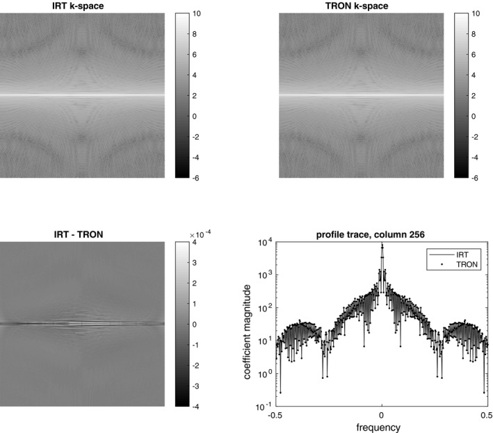
Degridded k‐space data generated from a radial sampling of the Shepp‐Logan phantom. TRON was everywhere within 0.04% of the values generated by IRT. The small difference we attribute to using an analytic deapodization instead of a computed one
Reconstructions of a Shepp‐Logan phantom are shown in Figure 2. All four packages were compared by reconstructing synthetic radial data created using IRT. TRON produced the lowest RMS image error. We again attribute the difference to the analytic deapodization and note that only TRON avoided adding artificial phase to the phantom. The TRON reconstruction was almost perfectly real with virtually zero imaginary component, unlike the other codes that produced a small, spurious imaginary component.
Figure 2.
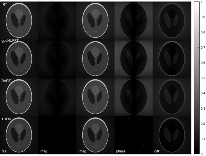
Reconstruction of the Shepp‐Logan phantom by all four codes from the IRT‐degridded k‐space. The slight improvement due to using an analytic deapodization instead of a computed one can be seen in the lack of artificially generated phase in the TRON result. RMS errors relative to the true phantom image for IRT, gpuNUFFT, BART, and TRON were 0.1143, 0.1016, 0.1143, and 0.0814, respectively. The difference images are unscaled
A test with a larger, whole‐body continuous moving table data set is shown in Figure 3. Only the magnitude images are shown because a sum‐of‐squares channel combination was used. TRON produced the highest structural similarity (SSIM) coefficient (0.996) relative to IRT, with BART at 0.989 and gpuNUFFT at 0.987. TRON reconstructed all 956 slices of the 6‐channel 512 × 512 whole‐body data in 3.28 s (572 μs per coil image, or 458 megavoxels/s). This was >30× faster than gpuNUFFT. Using IRT as the gold standard, structural similarity coefficients (SSIMs) for gpuNUFFT, BART, and TRON were 0.987, 0.989, and 0.996, respectively.
Figure 3.
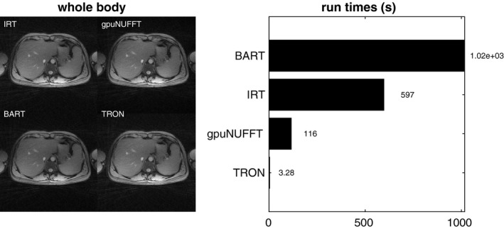
Reconstruction of whole‐body continuous moving table data from all four codes. Using IRT as the gold standard, structural similarity coefficients (SSIMs) for gpuNUFFT, BART, and TRON were 0.987, 0.989, and 0.996, respectively. Time to reconstruct 956 slices and 6 channels of 2× oversampled 512 × 512 whole‐body continuous moving table data. TRON was over 30× faster than the nearest competitor, which also used the GPU
Figure 4 shows the reconstruction of 15 dynamics and 8 channels of 2× oversampled 400 × 400 optic nerve data. TRON was again much faster, but due to the smaller data set, the discrepancy is smaller, with TRON being only 5× faster than gpuNUFFT. SSIMs for gpuNUFFT, BART, and TRON were 0.971, 1.000, and 0.988, respectively.
Figure 4.

Reconstruction of 15 dynamics and 8 channels of 2× oversampled 400 × 400 optic nerve data. Using IRT as the gold standard, SSIMs for gpuNUFFT, BART, and TRON were 0.971, 1.000, and 0.988, respectively
Figure 5 shows the reconstruction of 155 dynamics and 8 channels of 2× oversampled 464 × 464 swallowing data. TRON was once again far faster than gpuNUFFT, with a speedup of over 25×. SSIMs for gpuNUFFT, BART, and TRON were 0.970, and 1.000, and 0.986, respectively.
Figure 5.
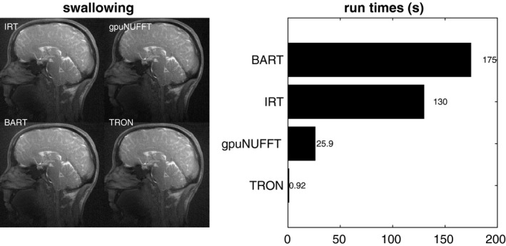
Reconstruction of 155 dynamics and 8 channels of 2× oversampled 464 × 464 swallowing data. Using IRT as the gold standard, SSIMs for gpuNUFFT, BART, and TRON were 0.970, and 1.000, and 0.986, respectively
Finally, Figure 6 shows a linear angle spacing example, a reconstruction of 108 slices and 2 channels of 2× oversampled 512 × 512 linear‐angle radial continuous moving table phantom data. TRON is much faster again. SSIMs for gpuNUFFT, BART, and TRON were 0.956, 1.000, and 0.963, respectively. We avoided cropping the phantom images so that any artifacts could be clearly seen.
Figure 6.
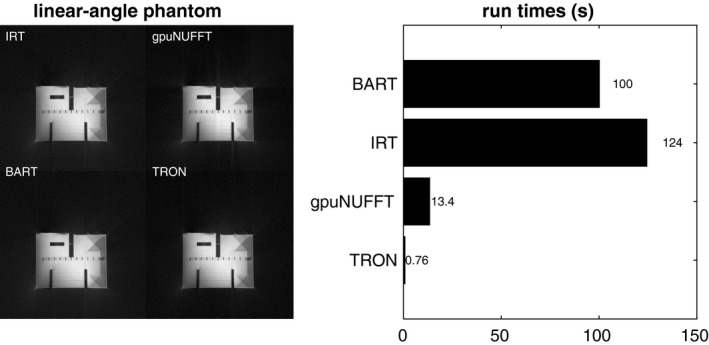
Reconstruction of 108 slices and 2 channels of 2× oversampled 512 × 512 linear‐angle radial continuous moving table phantom data. Using IRT as the gold standard, SSIMs for gpuNUFFT, BART, and TRON were 0.956, 1.000, and 0.963, respectively. Images were not cropped so that any artifacts could be clearly seen
While exact the speed improvement varied, TRON was by far the fastest code in all examples.
4. DISCUSSION AND CONCLUSIONS
Using the GPU, reducing memory transfers, eliminating write conflicts, and assuming an input sampling pattern, we dramatically accelerated the radial NUFFT. TRON was slightly more accurate, likely due to the analytic deapodization, but importantly it was much faster without sacrificing accuracy. Table 1 summarizes the different codes tested and their attributes.
Table 1.
Attributes of Codes Tested
| Code | Language | Hardware | Lines of Code | Trajectories | Corrections |
|---|---|---|---|---|---|
| IRT | Matlab | CPU | 1838 | any | any |
| BART | C | CPU | 75,000+ | any | any |
| gpuNUFFT | C++, CUDA | GPU | 16,000+ | any | any |
| TRON | C++, CUDA | GPU | 1977 | 2D radiala | noneb |
aCan be extended to other fixed trajectories, including 3D; bGradient delay correction can be added.
TRON can be extended to any trajectory that can be known a priori, including 3D trajectories, and even simple corrections, such as gradient delays, can be handled. Other trajectory errors (e.g.,21) could be corrected in the data prior to gridding as a pre‐processing step. The paradigm enabled by TRON is having a separate gridding function for each trajectory used, instead of one generic function that handles all trajectories. Metaprogramming could also be used to generate the CUDA kernal code on the fly before gridding.
As an aside on code complexity and accessibility, TRON is only 1977 lines long, while the minimal subset of IRT used here comprised 1838 lines, and gpuNUFFT included over 16,000 lines. We hope this demonstrates that GPU codes need not be complex and impenetrable. Smaller code bases lead to easier debugging and safer clinical application. Also, TRON does not require MATLAB, and it has a permissive license that allows it to be incorporated into commercial clinical software if desired.
The tremendous speed of TRON allows real‐time reconstruction of radial data at a framework higher than typical video frame rates of 24–60 frames per second. TRON could make it possible to explore and optimize data collection in real time and remove the clinical barrier of complex, non‐linear reconstructions that may contain artifacts that are difficult to interpret. And since TRON will run on even low‐end Nvidia GPUs, it could be easily and cheaply integrated into a clinical reconstruction pipeline without the requirement of expensive or scarce hardware (although better GPUs will naturally yield better performance).
TRON can be downloaded at http://github.com/davidssmith/TRON.18
Smith DS, Sengupta S, Smith SA, et al. Trajectory optimized NUFFT: Faster non‐Cartesian MRI reconstruction through prior knowledge and parallel architectures. Magn Reson Med. 2019;81:2064–2071. 10.1002/mrm.27497
Notes
Best, The Netherlands.
X‐tend ApS, Hornslet, Denmark
Invivo, Gainesville, Florida.
REFERENCES
- 1. Fessler JA, Sutton BP. Nonuniform fast Fourier transforms using min‐max interpolation. IEEE Trans Sig Proc. 2003;51:560–574. [Google Scholar]
- 2. Jackson JI, Meyer CH, Nishimura DG, Macovski A. Selection of a convolution function for Fourier inversion using gridding. IEEE Trans Med Imaging. 1991;10:473–478. [DOI] [PubMed] [Google Scholar]
- 3. Sorensen TS, Schaeffter T, Noe KO, Hansen MS. Accelerating the nonequispaced fast Fourier transform on commodity graphics hardware. IEEE Trans Med Imaging. 2008;27:538–547. [DOI] [PubMed] [Google Scholar]
- 4. Gregerson A. Implementing Fast MRI gridding on GPUs via CUDA. Nvidia Whitepaper 2008; Online: http://cn.nvidia.com/docs/IO/47905/ECE757_Project_Report_Gregerson.pdf. Accessed April 24, 2018.
- 5. Kunis S, Kunis S. The nonequispaced FFT on graphics processing units. PAMM. 2012;12:7–10. [Google Scholar]
- 6. Knoll F, Schwarzl A, Diwoky C, Sodickson D. gpuNUFFT—An Open‐Source GPU Library for 3d Gridding with Direct Matlab Interface. Proc ISMRM. 2014. Abstract4297.
- 7. Yang J, Feng C, Zhao D. A CUDA‐based reverse gridding algorithm for MR reconstruction. Mag Reson Imaging. 2013;31:313–323. [DOI] [PubMed] [Google Scholar]
- 8. Feng C, Zhao D. CUDA accelerated uniform re‐sampling for non‐Cartesian MR reconstruction. Bio‐Med Mat Eng. 2015; 26:S983–S989. [DOI] [PubMed] [Google Scholar]
- 9. Wu XL, Gai J, Lam F, et al. Impatient MRI: Illinois Massively Parallel Acceleration Toolkit for image reconstruction with enhanced throughput in MRI. In 2011 IEEE International Symposium on Biomedical Imaging: From Nano to Macro, March 2011, Chicago, IL pp. 69–72. [Google Scholar]
- 10. Gai J, Obeid N, Holtrop JL et al. More IMPATIENT: A gridding‐accelerated Toeplitz‐based strategy for non‐Cartesian high‐resolution 3d MRI on GPUs. J Parallel Dist Comput. 2013;73:686–697. [DOI] [PMC free article] [PubMed] [Google Scholar]
- 11. Ou T. gNUFFTW: Auto‐tuning for high‐performance GPU‐accelerated non‐uniform fast Fourier transforms [master's thesis]. Technical Report #UCB/EECS‐2017‐90; May 12, 2017, UC Berkley; 2017.
- 12. Feng L, Axel L, Chandarana H, Block KT, Sodickson DK, Otazo R. XD‐GRASP: Golden‐angle radial MRI with reconstruction of extra motion‐state dimensions using compressed sensing. Mag Reson Med. 2016;75:775–788. [DOI] [PMC free article] [PubMed] [Google Scholar]
- 13. Grimm R, Frst S, Dregely I, et al. Self‐gated Radial MRI for Respiratory Motion Compensation on Hybrid PET/MR Systems. In Medical Image Computing and Computer‐Assisted Intervention—MICCAI 2013, September 2013, Nagoya, Japan pp. 17–24. [DOI] [PubMed] [Google Scholar]
- 14. Rasche V, Holz D, Köhler J, Proksa R, Röschmann P. Catheter tracking using continuous radial MRI. Mag Reson Med. 1997;37:963–968. [DOI] [PubMed] [Google Scholar]
- 15. Sengupta S, Smith DS, Welch EB. Continuously moving table MRI with golden angle radial sampling. Mag Reson Med. 2015;74:1690–1697. [DOI] [PMC free article] [PubMed] [Google Scholar]
- 16. Walsh DO, Gmitro AF, Marcellin MW. Adaptive reconstruction of phased array MR imagery. Mag Reson Med. 2000;43:682–690. [DOI] [PubMed] [Google Scholar]
- 17. Smith D. Raw array format. Git Repository 2018; SHA: 80ce83f.
- 18. Smith D. Trajectory Optimized NUFFT. Git Repository 2018; SHA: 2257cd9.
- 19. Uecker M, Tamir JI. Berkeley Advanced Reconstruction Toolbox: Version 0.4.02, November 2017.
- 20. Wang Z, Bovik AC, Sheikh HR, Simoncelli EP. Image quality assessment: from error visibility to structural similarity. IEEE Transactions on Image Processing 2004; 13:600–612. [DOI] [PubMed] [Google Scholar]
- 21. Ahn CB, Cho ZH. A new phase correction method in NMR imaging based on autocorrelation and histogram analysis. IEEE Trans Med Imaging. 1987;6:32–36. [DOI] [PubMed] [Google Scholar]


