Abstract
Tubal sterilization with Essure inserts has become a prevalent alternative to laparoscopic sterilization because of its minimal invasiveness. It is a well-tolerated ambulatory procedure that provides reliable permanent contraception without the risks associated with laparoscopic surgery and general anesthesia. Correct positioning of the Essure device is necessary to achieve the fibrotic reaction induced by the polyethylene terephthalate fibers, subsequently resulting in tubal occlusion usually within 3 months. After uneventful procedures with satisfactory bilateral placement, only the correct position of the devices needs to be confirmed at follow-up. The imaging techniques used to asses Essure devices may vary depending on the country and its recommendations. The gold-standard test to ascertain tubal occlusion remains the hysterosalpingography but after uneventful procedures, vaginal-ultrasound proved to be a reliable alternative to confirm the proper position of the inserts. Radiologists have been increasingly confronted to post-procedural evaluations and despite the efficiency rate of the Essure device, its use still exposes to a low risk of complications and malfunctions such as unwanted pregnancies, device misplacement, tubal or uterine perforation, and chronic pelvic pain. Unintended pregnancies are mostly due to patient or physician non-compliance and misinterpretation of post-procedural examinations by radiologists which emphasizes the importance of their training in Essure device assessment. This pictorial review discusses the imaging methods used to asses Essure implants and illustrates the possible complications related to them.
Introduction
Tubal sterilization with Essure inserts has become a prevalent alternative to laparoscopic sterilization because of its minimal invasiveness. It was approved by the European Health Office in November 2001 and by the FDA in November 2002.
It’s a well-tolerated ambulatory procedure that provides reliable permanent contraception without the risks associated with laparoscopic surgery and general anesthesia.1
The procedure is carried out with hysteroscopic guidance and the insert is placed transcervically into the proximal portion of the fallopian tube. Each insert consists of a nickel–titanium alloy outer coil, a stainless steel inner coil wrapped in a layer of polyethylene terephthalate fibers2, 3 (Figure 1). These fibers induce a fibrotic reaction in the tubal lumen, resulting in a tubal occlusion usually within 3 months, at which point, it is necessary to confirm the proper position of the inserts by an imaging study.2 Meanwhile, patients are instructed to rely on an alternative contraception method until tubal occlusion is confirmed.
Figure 1.
Appearance of the Essure permanent birth control device on a photograph (a), a radiography (b) and a hysteroscopy (c). (a) A photograph of the device, which consists of two coils. The distal end of the inner coil has a small round shape “ball-tip”. The proximal end of the outer coil is recognized with its linear shape “platinum band”. The inner coil end of the device is inserted into the fallopian tube, and the outer coil end protrudes into the uterine cavity. The inner coil is coated with polyethylene terephthalate fibers, which stimulate a fibrotic reaction, causing the occlusion of the tubal lumen. The outer spring coil expands upon deployment and anchors the device within the cornua. (b) Radiographic appearance of an Essure microinsert with the four radio-opaque markers identified. (c) Hysteroscopic image of an Essure micro-insert with five trailing coils into the uterine cavity, through the tubal ostium. The proximal end of the outer coil is recognized by the platinum band.
Radiologists have been increasingly confronted to post-procedural evaluations and despite the success rate of the Essure device, its use still exposes to a low risk of complications and malfunctions4 such as unwanted pregnancies that are partly due to misinterpretation of post procedural examinations by radiologists,5 which emphasizes the importance of their training and theoretical knowledge concerning Essure device assessment.
This pictorial review discusses the imaging methods used to asses Essure implants and illustrates the different reported complications related to them.
Imaging techniques
Different imaging techniques can be used to asses Essure devices but the gold standard test to ascertain tubal occlusion remains the hysterosalpingography (HSG). It was in fact, the only FDA mandated requirement for all patients in the USA, to be performed 3 months after the procedure.2 HSG is an ionizing, inconvenient and often painful test that is also associated with adverse events, the most common being vasovagal reaction.
Correct positioning of Essure device is necessary to achieve fibrotic reaction and subsequently tubal occlusion.6 The success rate of Essure device was high enough3, 5 that tubal occlusion was no longer a necessary requirement and pelvic radiography was substituted for HSG to assess Essure device position after satisfactory bilateral placement.7 Still, it lacks soft tissue detail to properly assess the relationship between the coils and the fallopian tubes.
In 2003, trans-vaginal-ultrasound (TVU) was introduced as a potential imaging method to evaluate the position of Essure device.8 Since then, it has proven to be a reliable and reproducible imaging method in assessing inserts location after satisfactory bilateral placement.9 TVU is a non-ionizing, less uncomfortable and less invasive technique than HSG, and it seems to have similar performances in assessing Essure inserts compared to pelvic radiography.10
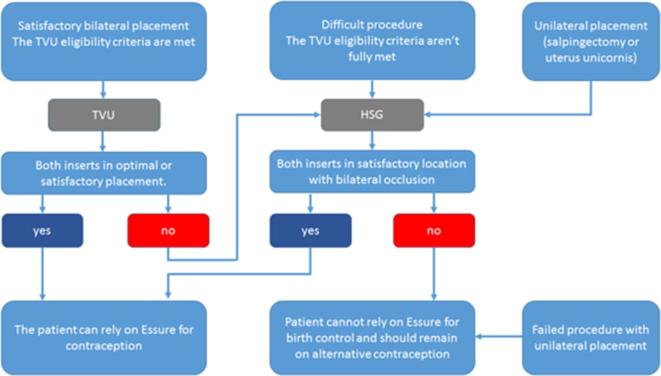
In 2015, the FDA approved two-dimensional-TVU as an alternative technique in evaluating Essure device position and a new algorithm including both TVU and HSG was introduced, detailing the indications of each technique2, 11 (Figure 2). This new protocol was deemed effective in determining if a patient could rely on the Essure device for contraception.11
Figure 2.
: Essure TVU/HSG confirmation test algorithm. HSG, hysterosalpingography; TVU, trans-vaginal-ultrasound.
TVU should be used in first-line to asses Essure inserts if the TVU eligibility (satisfactory bilateral placement) criteria are met: no excessive force or sudden loss of resistance during insertion of the implant, no difficulty identifying the ostia during the procedure, length of procedure ≤15 min, 1 to 8 trailing coils in both sides (Figure 1c), no unusual per or post-operative pain and absence of immunosuppressive therapy.2 If one of these criteria is not met, an HSG is necessary to evaluate the inserts.
Uterine bleeding decreases visibility during hysteroscopy. It is very common in females of reproductive age. Its known causes are endometrial or myometrial pathologies such as polyps, submucous myomas, endometrial hyperplasia or carcinoma and also iatrogenic and hormonal age-related causes. This issue tends to increase with age, especially in females over 40 years old, which are the targeted patients of tubal sterilization with Essure device.
Radiological assessment of essure birth control device
According to the device manufacturer, the device should extend across the uterotubal junction (UTJ) or the serosal-uterotubal junction (SUTJ) depending on the imaging technique used for the assessment. The UTJ refers to the proximal portion of the fallopian tube and is identified by HSG while the SUTJ refers to the region where the fallopian tube meets the serosal surface of the uterus and is identified by TVU.2
A-Pelvic X-Ray
The microinserts are easily detectable as two curvilinear and relatively symmetrical metallic devices with radiomarkers at the end of each coil. The lateral or tubal end of the insert is recognized by the distal marker of the inner coil which has a small round shape (ball-tip). The medial or uterine end of the insert is recognized by the proximal marker of the outer coil which has a linear shape (platinum band) (Figure 1b).
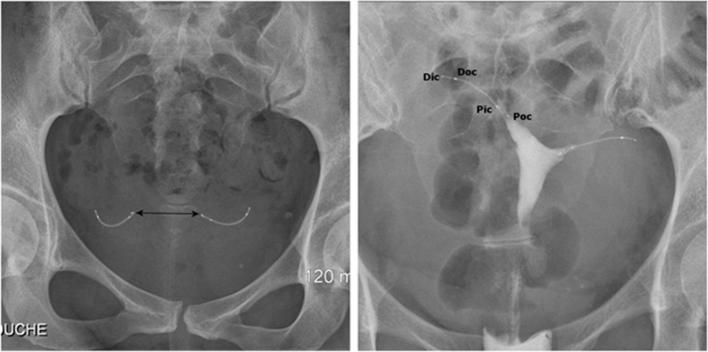
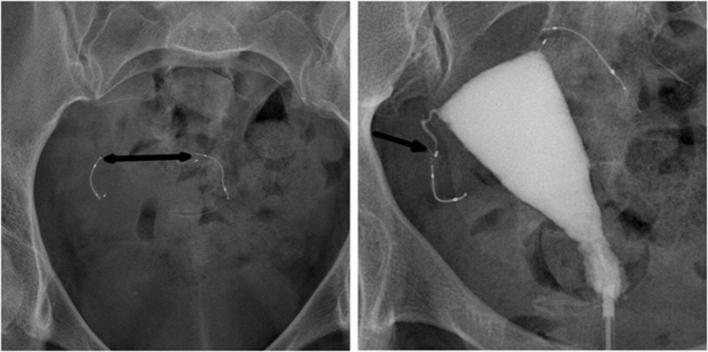
There are three main parameters to take into account when assessing Essure devices on a pelvic radiography2 (Figure 3a): (1) The symmetrical appearance of the two inserts. (2) The radiomarkers of each coil should be aligned without angulation of the microinserts. (3) The distance between the proximal markers of the microinserts should be inferior to 4 cm, which is the theoretical distance between the two ostia.
Figure 3.
Normal appearance of Essure birth control device on radiography (a) and hysterosalpingography (b). (a) Pelvic X-ray showing two symmetrical inserts, laying in the pelvic area without any abnormal configuration. Their radiomarkers are aligned and the distance between the proximal ends of the inserts is inferior to 4 cm. (b) Hysterosalpingogram showing correct placement of the two inserts with bilateral tubal occlusion. Both inserts have an intrauterine portion, an interstitial portion and a tubal portion. Contrast agent fills both cornual regions without progression into the fallopian tubes or intraperitoneal spillage. Pic/Dic, proximal and distal markers of the innercoil; Poc/Doc, proximal and distal markers of the outercoil.
Because of certain uterine abnormalities such as fibroma or adenomyosis, this distance can be increased.10 Pelvic radiography has several limitations in unusual situations such as single Essure device placement (unilateral salpingectomy or uterus unicornis), uterine laterodeviation or retroversion.6
B-Hysterosalpingography
HSG is the only imaging technique that allows us to test the mechanical integrity of the fibrotic reaction thus evaluating the tubal occlusion and device positioning at the same time.
The microinserts are considered “functional” if they are relatively symmetrical, placed adequately in the UTJ with no tubal patency2 (Figure 3b).
A grading system based on HSG can determine the satisfactory or unsatisfactory position of the microinserts.2
Grade 1: indicates expulsion of the device into the uterine cavity or proximal placement of the device with more than 50% of the inner coil trailing into the uterine cavity.
Grade 2 (satisfactory placement): when the distal marker of the inner coil is within the fallopian tube with <50% of the inner coil’s length trailing into the uterine cavity, or when the proximal end of the inner coil appears to be ≤30 mm into the tube from contrast filled cornua.
Grade 3 (distal placement or perforation): when the insert is in the tube but the proximal end of the inner coil is located more than 30 mm from contrast filled cornua or when the insert is completely or partially perforated.
Grade 4: indicates device extrusion into the peritoneal cavity.
Satisfactory occlusion is defined by bilateral tubal occlusion at the cornua or an opacification of the fallopian tube that does not extend past the distal end of the outer coil.
Excessive or insufficient pressure during contrast instillation, tubal spasm and intravasation can cause false-positive or false-negative results.
C-Ultrasound
TVU can reliably identify the microinserts as echogenic linear structures at both ends of the uterine cavity.8, 9 It should be performed in the luteal stage so that the thickness of the endometrium will enhance the visibility of the microinserts in the proximal portion of the fallopian tube. The rest of the microinsert located in the fallopian tube is obscured by the bowel gas surrounding the fallopian tube.
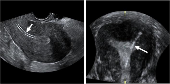
An insert position is considered satisfactory if the linear axis of the microinsert can be visualized crossing the SUTJ and its medial end is in contact with the endometrium or the uterine cavity. The insert is not necessarily seen beyond the SUTJ2 (Figure 4b).
Figure 4.

Normal appearance of Essure birth control device on 2D-TVUS (a, b) and 3D-TVUS (c, d). (a) Axial ultrasound image of the uterus showing both inserts in the cornual regions. This acquisition avoids the risk of duplicate imaging of the same insert that can happen if the probe is turned 180 degrees during the examination. (b) An oblique transverse image of the uterus showing the linear axis of the insert in the interstitial portion of the fallopian tube, crossing the right SUTJ. The linear axis is not coiled. The proximal end of the insert is in contact with the endometrium. The insert is not seen beyond the SUTJ. The serosal boundary is delineated by the dotted line. (c) Volume contrast 3D reconstructed image in the coronal plane demonstrating a uterus with two inserts in perfect position (1 + 2 + 3). The medial end of the left insert is in the uterine cavity. The medial end of the right insert is in contact with the endometrium. (d) Coronal reconstruction from a 3D ultrasound acquisition, showing a uterus with two inserts in perfect position (1 + 2 + 3). 2D, two-dimensional; 3D, three-dimensional; SUTJ, serosal-uterotubaljunction; TVU, trans-vaginal-ultrasound.
On the opposite, if the microinsert is not identified within the cornua, crossing the SUTJ, the position is deemed unsatisfactory due to migration in the tube or in the uterine cavity.2
If the surrounding soft tissues to the insert are not clearly identified, if the insert is coiled or bent, the location is also considered unsatisfactory.2
Legendre et al developed a classification to assess the position of the Essure device that relies on the coronal section of the uterus obtained after a three-dimensional acquisition6 (Figure 5).
Figure 5.

Legendre’s three-dimensional ultrasound classification to assess Essure device position: perfect position (1 + 2 + 3), proximal position (1 + 2), distal position (2 + 3) and very distal position (3-only).
In this classification, four different positions are described:
The perfect position (1 + 2 + 3) includes an intrauterine portion, a cornual portion and an isthmic portion (optimal).
A proximal position (1 + 2) includes an intrauterine and a cornual portion (suboptimal).
A distal position (2 + 3) with no intracavitary portion (suboptimal).
A very distal position (3 only) located in the isthmic portion of the fallopian tube.
In a study conducted by Legendre et al, three-dimensional-ultrasound and this classification have been validated to assess the inserts position.6 Only the very distal position (3 only) showed a significant association with failed tubal occlusion and thus, HSG is required only if the insert position is classified 3-only.6
Complications and device malfunctions
Even though complications associated with Essure implants are rare, they are commonly missed during the procedure and can be frequently asymptomatic in the post-procedural phase.4 Therefore, they must be sought out thoroughly during follow-up examinations as misinterpreted images by radiologists are a common cause of unwanted pregnancies, the main cause being patient or physician non-compliance.5
The most common form of patient non-compliance found in literature is failure to return for the 3 months HSG follow-up.5 This emphasizes the need for less invasive tests that are considered more acceptable by patients.
Imaging findings should be correlated with the operative report regarding the difficulty of the procedure, suspicion of complication and the number of trailing coils.
Clinical presentations of complications related to Essure procedures are widely variable. Patients may experience pelvic pain, cramping, nausea, vomiting or bleeding.2, 12 Nevertheless, an absence of symptom does not preclude such complications,4 especially if the procedure was reported as difficult by the surgeon.
Essure insertion can be associated with chronic pelvic pain and the main causes frequently found after investigation are insert’s misplacement, device migration and tubal perforation.
Furthermore, late onset symptoms may appear after the 3 months follow-up and should alert the physician to the possibility of a complication.
Structural abnormalities
Structural abnormalities are best identified by pelvic X-ray or HSG. Insert fracture or stretching of the proximal outer coil may occur upon device deployment (Figure 6). These complications are usually noticed during the procedure and removal of the device is generally attempted immediately afterward.
Figure 6.
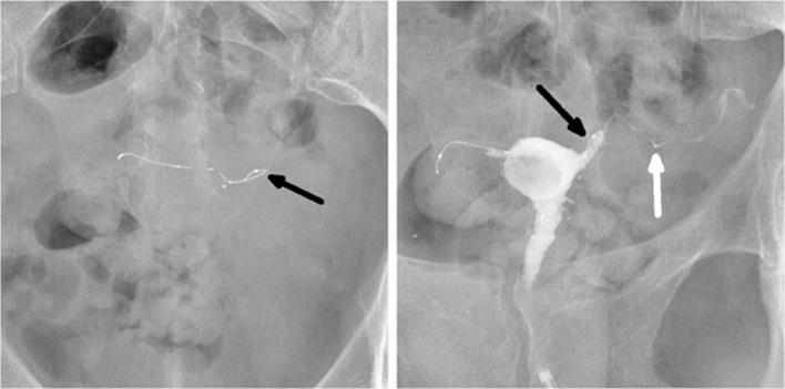
A 34-year-old female with a history of a left-sided tubal stump pregnancy, a year after undergoing laparoscopic tubal ligation. Following the failure in sterilization, tubal occlusion with Essure device was proposed to her. The procedure was described as difficult with poor visibility because of endometrial bleeding and debris. The right implant was deployed with eight trailing coils visible in the uterine cavity. On the left side, a first implant was placed with no trailing coils visible after deployment. The surgeon suspected distal placement and decided to place another insert that left six trailing coils after deployment. (a) Hysterosalpingogram performed before Essure placement, showing bilateral tubal patency in both tubal stumps (arrow). (b) Scout image showing two inserts on the left side of the pelvic cavity, one of them having a straight shape, and distal migration of the right insert (arrowhead) after detachment from its proximal marker (arrow). (c) Hysterosalpingogram showing tubal occlusion of the right side and tubal patency of the left side (arrow) despite a correctly placed insert. On the right side, the outer coil is not delineated by the dye in the tube and the important distance between the proximal marker and the rest of the insert suggests a fracture rather than a stretching. Tubal perforation with the second “left” implant was suspected because the second implant was projected outside the uterine cavity and did not follow the course of the fallopian tube that was delineated by the contrast agent (arrowhead). Tubal perforation was confirmed during laparoscopic surgery.
Hysteroscopic removal of microinserts may cause insert fracture or tubal perforation if the number of trailing coils is less than 18. Hysteroscopy and other intrauterine procedures may also cause insert’s fragmentation or displacement.2
However, it should be noted that because of the outer coil’s flexibility, its proximal marker may seem slightly stretched while the rest of the markers are fixed in relation to one another (Figure 7).
Figure 7.
A 26-year-old female with a history of laparoscopic salpingectomy for a right-sided ectopic pregnancy. (a) Scout image showing normal stretching of the proximal end of the outer coil (arrow). (b) Hysterosalpingogram showing correct placement of the left insert with a normal stretching of the outer coil (arrow). The outer coil is slightly visible, connecting the proximal marker to the rest of the insert. Although the outer coils aren’t radiopaque, they can be delineated by the contrast filling the tube. (c) HSG image of another patient showing the outer coil being delineated by the contrast in the fallopian tube. HSG, hysterosalpingography.
Differentiating between an insert fracture or stretching can be challenging because the outercoil is not radiopaque, but it can be delineated by the contrast agent filling the tube2 (Figure 7c) and therefore, its integrity and morphology can be evaluated. Additionally, if the distance between the proximal marker and the rest of the insert is important (Figure 6), it is more likely to be due to a fracture than a stretching.
Device migration and misplacement
Insert misplacement is best identified by HSG or TVU. In case of unsatisfactory positioning on HSG (Grade 1, 3 and 4), it is assumed that the fibrotic reaction was not properly induced, thus rendering the inserts inefficient. Depending on the case, the device can be replaced. Otherwise, the patient must undergo laparoscopic tubal ligation.
After Essure device insertion, inserts can migrate proximally into the uterine cavity (Figure 8), sometimes to the point of expulsion (Figure 9) or distally through the fallopian tubes (Figure 10) and into the peritoneal cavity (Figure 11).
Figure 8.
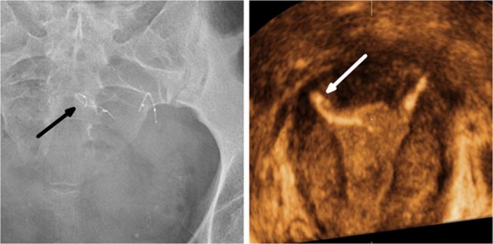
A 48-year-old multiparous female presenting with chronic left iliac fossa pain. The patient had Essure bilateral placement performed 3 years prior to the examination. (a) Transvaginal ultrasound image: midsagittal section of the uterus showing the long axis of the insert (arrow) in the uterine cavity. (b) 3D reconstructed coronal view of the uterus showing proximal migration of the left insert (arrow). 3D, three-dimensional.
Figure 9.
A 44-year-old female who underwent tubal sterilization with Essure implants. The procedure was noted as difficult because of poor visibility and a right-sided tubal spasm. (a) Scout image showing asymmetrical inserts. (b) Hysterosalpingogram showing bilateral tubal occlusion despite a misplaced right implant. Peritoneal extrusion was suspected because the insert wasn’t projected inside the uterine cavity (arrow). (c) Delayed HSG image. The patient experienced shortly afterward, a vaginal expulsion of the right insert. This was due to a proximal migration of the insert that positioned itself in the vaginal fornix (arrow), which is consistent with the imaging findings of the image (c). In this case, differentiating between a localization in the recto-uterine pouch and the vaginal fornix cannot be done on radiographic or HSG images. Peritoneal extrusion was suspected because the implant was lodged in the pelvic area for 3 months after the procedure and should have been extruded vaginally earlier in the follow-up period. An approach with a CT scan would have been better suited to localize the implant with more precision. HSG, hysterosalpingography.
Figure 10.
A 35-year-old female who underwent tubal sterilization. (a) Scout image showing an increased inter implant distance superior to 4 cm. (b) Hysterosalpingogram showing distal malposition of the right insert (arrow) with bilateral tubal occlusion.
Figure 11.
A 41-year-old female presenting with fever and iliac fossa pain, a month after a difficult Essure placement procedure. (a) Anteroposterior pelvic radiography showing asymmetrical inserts. (b) Lateral pelvic radiography showing an anterior position of the left implant (arrow). (c) Transvaginal-ultrasound image: transverse section of the uterus (star) showing a collection (arrowhead) centered around the left insert (arrow) in the peritoneal cavity. Laparoscopic surgery confirmed the extrusion of the left insert which was positioned in the omentum.
Poor visualization during the procedure is a common factor of device misplacement (Figures 12 and 13).
Figure 12.
A 45-year-old multiparous female who underwent a complicated Essure procedure because of poor visibility with 14 trailing coils visible after the deployment of the right insert. A history of angioedema after an intravenous urography prevented the use of hysterosalpingography. (a) A pelvic radiography showing a curled right insert (arrow). (b) 3D reconstructed coronal view of the uterus confirming the abnormal configuration of the insert (arrow) in the right cornua. 3D, three-dimensional.
Figure 13.
A 45-year-old female who underwent two attempts of Essure placement with a failure inserting the implant in the right ostium during the first attempt. Endometrial bleeding obscured visibility during the second attempt which misled the surgeon to insert a second implant on the left side. Uterine perforation was confirmed during surgery. (a) Hysterosalpingogram (performed before the second attempt) showing a correctly positioned insert in the left side (arrow) with normal bilateral tubal patency. (b) Pelvic X-ray performed after the second attempt, showing two inserts in the left side of the pelvic cavity. (c) 3D reconstructed coronal oblique view of the uterus showing one correctly placed insert (white arrow) localized in the cornua and following laterally the expected course of the fallopian tube. The second implant (black arrow) is localized medially to the cornua and crosses through the myometrium (white star), which is suggestive of uterine perforation. Additionally, the first insert seemed correctly placed in the tubal lumen on the first HSG and the second insert had a different course with a different entrance point (white star) in the uterine wall that couldn’t have been the tubal ostium. (d) Illustration depicting the misplaced insert in the coronal plane. The insert is localized medially to the left superior angle of the uterine cavity which represents the left tubal ostium, and crosses through the myometrium. 3D, three-dimensional; HSG, hysterosalpingography
Tubal expulsion into the uterine cavity is most commonly due to proximal misplacement of the inserts with rates ranging from 0.4 to 3%.1, 12 It is also reported to be the most common finding associated with unwanted pregnancies.5
An overly distal placement of the device is associated with an increased risk of tubal perforation and extrusion of the device into the peritoneal cavity.4 Device extrusion into the peritoneal cavity is a rare complication, with a reported rate of 0.04 %.12 In such cases, the device must be surgically removed as it can cause chronic pain and induce peritoneal adhesions potentially leading to small bowel obstruction.
Tubal or uterine perforation
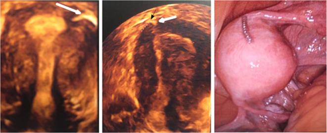
Tubal or uterine perforation is a difficult and relatively rare diagnostic. Its rate ranges from 1 to 2%1, 3 (Figure 14). The difficulty of the diagnostic lies in the poor specificity of the radiographic findings. A kink in the insert or a straight aspect of the implant are described on radiographs as possible signs of perforation.2
Figure 14.
A 36-year-old female who underwent tubal sterilization with the Essure system. A mild resistance was encountered while inserting the right implant. The follow-up test consisted of a TVUS without HSG or X-ray because the surgeon was satisfied with the procedure and confident that the inserts were correctly placed. An unwanted pregnancy occurred 6 months after the procedure and a medical abortion was performed. The patient underwent laparoscopic tubal ligation during which an Essure-related uterine perforation was diagnosed. (a) 3D reconstructed coronal view of the uterus showing a proper position of the left insert (arrow). (b) 3D reconstructed coronal view of the uterus showing a satisfactory placement of the right insert (white arrow) (position 2 + 3 according to Legendre’s classification) that comes in contact with the SUTJ (black arrow). The serosal boundary is delineated by the dotted line. The tubal portion of the insert is not visible. (c) Laparoscopic view confirming subserosal misplacement of the right insert. 2D,two-dimensional; 3D, three-dimensional; SUTJ, serosal-uterotubaljunction; TVU, trans-vaginal-ultrasound.
Anteriorly to the imaging examination, tubal or uterine perforation should be suspected if one of these elements is mentioned in the procedure report: poor visualization of the tubal ostia, tubal spasm and forced progression of the insert despite resistance.3 The surgeon may describe overcoming a resistance or a sudden loss of resistance, which would be the moment the perforation occurred.
Other causes related to perforations are tubal anomalies such as obstruction, stenosis and lumen distortion.
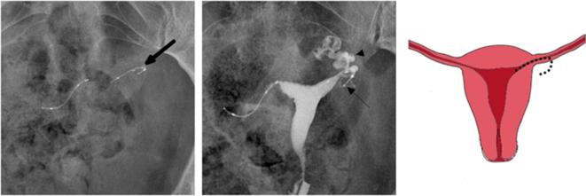
On HSG, the association of tubal patency with an abnormal configuration of the insert (curled, sharp bend) is suspicious for perforation.2 Additionally, HSG can reveal an Essure-related perforation by showing an embedded insert in the myometrium or an aberrant trajectory of the insert that is different from the tubal dye filled trajectory2 (Figure 15).
Figure 15.
A 37-year-old nulliparous female who underwent bilateral Essure placement. A second hysterosalpingography was required six months after the procedure because of bilateral tubal patency in the first follow-up. (a) Scout image showing an asymmetrical aspect of the inserts with a curved left insert (arrow). (b) Hysterosalpingogram showing proper placement of the two inserts and persistent left tubal patency. The lateral end of the left insert (arrow) deviates from the trajectory of the contrast filled ampulla and infundibulum of the fallopian tube (arrowhead) which is consistent with tubal perforation. Laparoscopic tubal ligation was performed and confirmed tubal perforation with subserosal misplacement of the left insert. (c) Illustration depicting the tubal perforation with the left insert deviating from the course of the fallopian tube.
On ultrasound, uterine perforation can be suspected if the linear axis of the insert is parallel to the endometrial stripe in the sagittal view or if the linear axis of an insert is visualized crossing through the myometrium2 (Figure 13).
Tubal patency
Assessment of tubal occlusion requires an imaging study by modified HSG.
Tubal patency is defined by the progression of contrast material past the distal end of the outer coil or by intraperitoneal spillage of contrast material. It can be caused by an incorrect placement of the insert, thus affecting the fibrosis process (Figure 16) or by tubal perforation.
Figure 16.
A 43-year-old female who underwent a satisfactory bilateral Essure device placement. (a) Scout image showing a kinked left insert (arrow) (b) Hysterosalpingogram showing a curled insert in the left cornua (black arrow) associated with ipsilateral tubal patency (white arrow). Tubal perforation was suspected because of the kinked aspect of the insert but hysteroscopy confirmed the proximal migration of the left insert with 15 trailing coils inside the uterine cavity.
Tubal occlusion is achieved after 3 months if the device is properly placed. However, it can also be achieved in case of distal positioning of the inserts. Failure of tubal occlusion can occur, despite a satisfactory location of the inserts. In that case, a second HSG study is required in another 3 months, as tubal occlusion can be obtained with additional time.2
Conclusion
Essure-related complications may be rare but often misdiagnosed. They may lead to adverse events and device malfunction such as unwanted pregnancies and chronic pelvic pain.
To ensure an early diagnosis of these complications, it is essential to choose the right imaging modality for the 3-month follow-up by thoroughly following the confirmation test algorithm. TVU is a safe and efficient alternative to HSG in cases of successful bilateral placement but should not be used in first line if the TVU eligibility criteria are not met. HSG can be inconvenient and painful for patients but it remains the gold standard imaging modality for assessing Essure inserts and is necessary after difficult procedures.
These complications can be suspected upon information found in the operative report regarding the difficulty of the procedure or any unusual event such as resistance during the insertion of the device or a persistent pelvic pain.
Patients should be advised not to rely on Essure device for contraception in case of unsatisfactory placement or any other Essure-related complication.
Contributor Information
Hachem Djeffal, Email: dr.djeffal.h@gmail.com.
Marie Blouet, Email: blouet-m@chu-caen.fr.
Anne-Cécile Pizzoferato, Email: pizzoferrato-ac@chu-caen.fr.
Delphine Vardon, Email: vardon-d@chu-caen.fr.
Frederique Belloy, Email: belloy-f@chu-caen.fr.
Jean-Pierre Pelage, Email: pelage-jp@chu-caen.fr.
REFERENCES
- 1.Cooper JM, Carignan CS, Cher D, Kerin JF, Selective Tubal Occlusion Procedure 2000 Investigators Group . Microinsert nonincisional hysteroscopic sterilization. Obstet Gynecol 2003; 102: 59–67. [DOI] [PubMed] [Google Scholar]
- 2.Essure healthcare professionals website ‘instructions for use’ [Internet]. 2017. Available from: http://labeling.bayerhealthcare.com/html/products/pi/essure_ifu.pdf [cited 2017 Sep 5].
- 3.Kerin JF, Carignan CS, Cher D. The safety and effectiveness of a new hysteroscopic method for permanent birth control: results of the first Essure pbc clinical study. Aust N Z J Obstet Gynaecol 2001; 41: 364–70. doi: 10.1111/j.1479-828X.2001.tb01311.x [DOI] [PubMed] [Google Scholar]
- 4.Guelfguat M, Gruenberg TR, Dipoce J, Hochsztein JG. Imaging of mechanical tubal occlusion devices and potential complications. Radiographics 2012; 32: 1659–73. doi: 10.1148/rg.326125501 [DOI] [PubMed] [Google Scholar]
- 5.Levy B, Levie MD, Childers ME. A summary of reported pregnancies after hysteroscopic sterilization. J Minim Invasive Gynecol 2007; 14: 271–4. doi: 10.1016/j.jmig.2006.11.007 [DOI] [PubMed] [Google Scholar]
- 6.Legendre G, Levaillant JM, Faivre E, Deffieux X, Gervaise A, Fernandez H. 3D ultrasound to assess the position of tubal sterilization microinserts. Hum Reprod 2011; 26: 2683–9. doi: 10.1093/humrep/der242 [DOI] [PubMed] [Google Scholar]
- 7.Heredia F, Cos R, Moros S, Torrabadella L, Cayuela E. Radiological control of Essure placements. Gynecol Surg 2004; 1: 201–203. doi: 10.1007/s10397-004-0038-8 [DOI] [Google Scholar]
- 8.Teoh M, Meagher S, Kovacs G. Ultrasound detection of the Essure permanent birth control device: a case series. Aust N Z J Obstet Gynaecol 2003; 43: 378–80. doi: 10.1046/j.0004-8666.2003.00102.x [DOI] [PubMed] [Google Scholar]
- 9.Veersema S, Vleugels MP, Timmermans A, Brölmann HA. Follow-up of successful bilateral placement of Essure microinserts with ultrasound. Fertil Steril 2005; 84: 1733–6. doi: 10.1016/j.fertnstert.2005.05.047 [DOI] [PubMed] [Google Scholar]
- 10.Moureau D, Laurent N, Rubod C, Lucot JP, Salleron J, Faye N. Evaluation of tubal microinserts position using 3D ultrasound and pelvic X-ray. Diagn Interv Imaging 2015; 96: 1133–40. doi: 10.1016/j.diii.2014.12.013 [DOI] [PubMed] [Google Scholar]
- 11.Vleugels M, Cheng RF, Goldstein J, Bangerter K, Connor V. Algorithm of transvaginal ultrasound and/or hysterosalpingogram for confirmation testing at 3 months after essure placement. J Minim Invasive Gynecol 2017; 24: 1128–35. doi: 10.1016/j.jmig.2017.06.021 [DOI] [PubMed] [Google Scholar]
- 12.Povedano B, Arjona JE, Velasco E, Monserrat JA, Lorente J, Castelo-Branco C. Complications of hysteroscopic Essure ® sterilisation: report on 4306 procedures performed in a single centre. BJOG 2012; 119: 795–9. doi: 10.1111/j.1471-0528.2012.03292.x [DOI] [PubMed] [Google Scholar]


