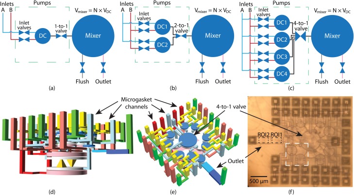
FIG. 8.
(a)–(c) Schematic of PDMPs with 1, 2, and 4 DIPs, respectively. A DIP has 2 inlet valves to enable pumping from either fluid source. The 1-to-1 valve is a normal valve, but a n-to-1 valve controls connecting n inlets to 1 outlet. (d) and (e) Different perspectives of a PDMP CAD design with 4 pumps and a 4-to-1 valve. The green vertical channels are fluidic channels, and the rest are control (pneumatic) channels. The outlet channel consists of two sections with heights of (ROI1) and (ROI2), respectively. (f) Microscope photo of a 3D printed device based on (d) and (e). Inside the white dashed box are 2 inlet valves and a DC.

