. 2018 Dec 18;7:e39441. doi: 10.7554/eLife.39441

Figure 2. Dynamin shape changes and membrane response.

(a) Top and (b) Side-view of dynamin dimers assembled into an unconstricted helical filament. (c) CG representation of a constricted filament. (d) Constricted and elongated filament. (e) Constricted and rotated filament. (f) Radius of gyration Rg of the membrane neck (see Materials and methods section) as a function of filament radius R under four protocols: constriction only (blue) constriction+rotation (cyan), constriction+rotation+elongation (dark cyan), constriction+elongation (dark blue). (g) An unconstricted filament resting on a membrane of matching radius (left) creates a Darboux-torque once the (red) adhesion strip is rotated (right), inducing the membrane to asymmetrically bulge; the two arrows indicate the torque couple. (h) Cross-sectional view of a 1- and 1.5-turn helical scaffold at R=10.5 σ and a 3.5-turn scaffold at R=10σ. The filament was constricted and rotated, only the adhesion strip is shown. Hemifission seeds are small pores, visible as breaks in bilayer continuity (arrows). (i) Cross-cut illustration of membrane shape changes triggered by a simultaneous filament constriction, rotation, and gradual disassembly (Video 5), leading to hemifission. (j) Continuation of the previous sequence from hemifission to complete fission.

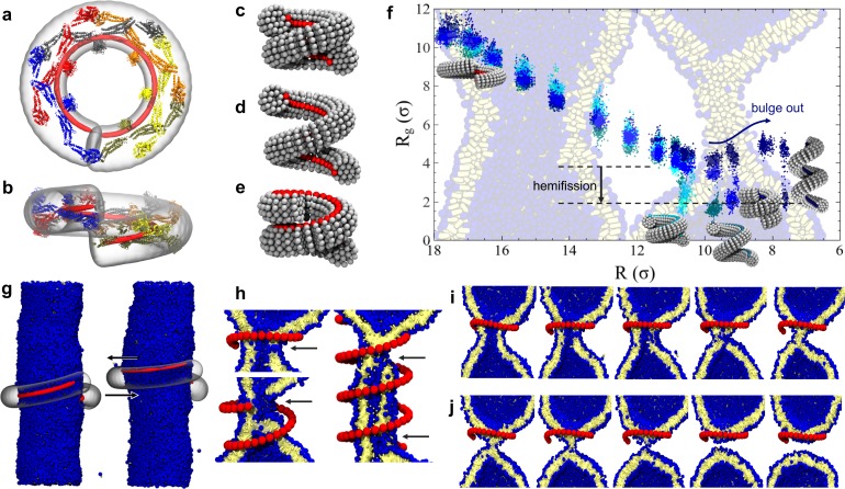
Figure 2—source data 1. Constriction-elongation trajectory.
DOI: 10.7554/eLife.39441.010
Figure 2—source data 2. Constriction-rotation-elongation trajectory.
DOI: 10.7554/eLife.39441.011
Figure 2—source data 3. Constriction-rotation trajectory.
DOI: 10.7554/eLife.39441.012
Figure 2—source data 4. Pure constriction trajectory.
DOI: 10.7554/eLife.39441.013

Figure 2.

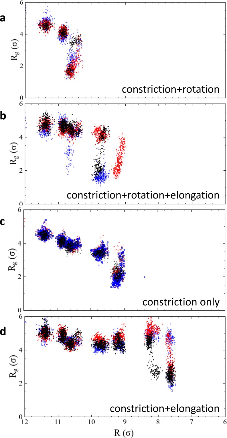
Figure 2—figure supplement 1. Results of repeated simulation trajectories for the four different constriction protocols presented in Figure 2f.

Figure 2—figure supplement 1.

The black dots are the same data as shown in the main article, the red and blue dots stem from two additional runs. In the two cases of constriction and constriction + rotation, all three trajectories transition into the hemifission state at exactly the same constriction step, while the cases constriction + elongation and constriction + rotation + elongation exhibit some scatter. We attribute this to the larger freedom that the enclosed membrane has in a helical scaffold that features an ever-widening groove due to the elongation component of the shape transformation. Figure 2—source data 1. The data from panel 2 f, as well as the repeated runs shown in Figure 2—figure supplement 1, are given as text-files containing Rg as a function of R for all four constriction scenarios.
Figure 2—figure supplement 1—source data 1. Constriction-elongation trajectories.
DOI: 10.7554/eLife.39441.006
Figure 2—figure supplement 1—source data 2. Constriction-rotation-elongation trajectories.
DOI: 10.7554/eLife.39441.007
Figure 2—figure supplement 1—source data 3. Constriction-rotation trajectories.
DOI: 10.7554/eLife.39441.008
Figure 2—figure supplement 1—source data 4. Pure constriction trajectories.
DOI: 10.7554/eLife.39441.009