

Abstract
Methods
Gamma Knife Icon™’s high-definition motion management (HDMM) system gates treatment delivery should intra-fraction displacement of a nose marker exceed some user-defined threshold. A method, previously-validated with a phantom, is used to relate intra-fractional displacements of the nose marker to displacements of patient targets. Additionally, novel analysis is performed to ascertain the relationship between nose marker displacement and displacement of a 3D grid of coordinates throughout stereotactic space. This spatial information is used to retrospectively review HDMM threshold levels based upon real target locations.
Results
For 41 targets from 22 patients, the mean(standard deviation) and maximum target-to-nose displacement ratio was 0.54(0.32) and 1.65, respectively. On average, displacements typically exceed those of the nose only for coordinates at the most extreme peripheral corner of the investigated 3D grid of points. Allowing target displacement of up to a maximum of 0.8mm, retrospective review indicated that at the locations of the 41 targets a median(range) HDMM threshold of 1.4(1.0-1.9) mm could have been adopted, compared to our standard threshold of 1.0mm.
Conclusions
Intracranial targets typically displace by a magnitude around half that of the nose. Novel analysis to determine the spatial variation of target-to-nose displacement ratio suggests, for our 41 targets, HDMM threshold could have been increased from our standard. Cases for which HDMM threshold could be safely increased would minimise treatment gating events and expedite treatment delivery to offer patient comfort benefits.
Keywords: Gamma Knife, Icon, mask, intra-fraction motion, gating, nose tracking, CBCT
Introduction
Launched in 2015, the Icon™-model Gamma Knife® (GK) (Elekta Instrument AB, Stockholm, Sweden) introduced two salient features compared to earlier GK models, namely: an integral cone beam CT (CBCT) system [1] and an infrared stereoscopic camera known as the high definition motion management (HDMM) system [2]. Together, these two new features allowed for the first time frameless GK stereotactic radiosurgery (SRS) to be performed using a thermoplastic mask and so offer a practical solution for delivery of fractionated GK SRS [3].
Whilst the CBCT system negates the use of a frame for stereotactic coordinate definition, the use of a mask for immobilisation represents a loss of confidence in patient set-up reproducibility and stability that is well-established using a conventional frame-based approach. In order to address inter-fraction set-up variation a pre-treatment CBCT is acquired immediately prior to delivery of each fraction and co-registered against the stereotactic reference CBCT [4]. The rigid co-registration translations and rotations are then applied to each planned shot coordinate so creating an adapted treatment plan of shots whose locations are shifted with respect to stereotactic space in order that they maintain their planned locations with respect to the anatomy [3,5].
During subsequent delivery of the adapted treatment plan, intra-fraction motion is monitored by the HDMM system, which tracks real-time displacement of a reflective marker on the tip of the patient’s nose relative to four immobile reflectors fixed to the Icon™ head support system. If the HDMM system detects nose marker displacement of a magnitude beyond some user-defined threshold level, irradiation is automatically interrupted (gated) [2]. Irradiation will only resume once the magnitude of displacement returns below threshold; should this not occur, treatment can only proceed upon acquisition of a new CBCT scan to allow shot coordinates to be adapted based upon the patient’s new position.
Whilst the accuracy of the shot coordinate adaption is relatively easily verified via end-to-end testing [6,7], confidence in the relationship between nose marker displacement and intracranial target displacement is less easily established. As has been previously described [8], use of the HDMM system raises two important questions: firstly, how does the displacement of an intracranial target relate to the HDMM measurement of nose marker displacement? And, secondly, what is an appropriate level for the user-defined threshold beyond which the HDMM system will interrupt treatment delivery? By default Icon™ sets the HDMM threshold to 1.5mm, but will allow any value up to 3mm. Whilst previous studies have presented findings that partially address these questions, they are based upon either limited linac data [9] or, primarily, phantom data [8].
Given the current paucity of data to help inform users of appropriate HDMM thresholds, in this study the authors aim to utilise a technique for relating nose marker and target displacements, previously validated with a phantom study [8], in order to investigate that relationship for real patients undergoing mask-immobilised GK SRS. Furthermore, using this patient-derived data the authors present results of a novel analysis to establish how that relationship varies throughout stereotactic space. It is hoped that this spatial information will, in future, lead to more informed choices of HDMM threshold levels based upon individual target locations.
Background
A method for relating the magnitude of HDMM-reported nose marker displacement to the magnitude of intracranial target displacements has been previously presented in detail [8]. For completeness, a summary is provided here.
Following manufacture of the patient’s mask, the stereotactic reference CBCT scan (CBCTSTXref) is acquired, against which the planning images are automatically co-registered within the Leksell GammaPlan (LGP) planning system (Elekta Instrument AB, Stockholm, Sweden) using a rigid mutual information algorithm [4,10,11]. Subsequently a planned set of shots with stereotactic coordinates {Splanned} is devised.
Immediately prior to the delivery of these planned shots, the pre-treatment setup CBCT scan (CBCTsetup) is acquired, which also zeros the HDMM system (based upon the HDMM data averaged over the 30 second duration of the scan). Within LGP, CBCTsetup is rigidly co-registered back to the initial CBCTSTXref and the resulting translations (Δx, Δy, Δz) and rotations (θx, θy, θz) – where axes x, y and z correspond to the left-right, anterior-posterior and superior-inferior directions, respectively – are then used by LGP to derive the adapted coordinates of each shot, Ssetup (1):
(1).
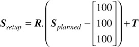
where translation matrix 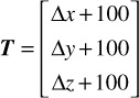
and rotation matrix 
with 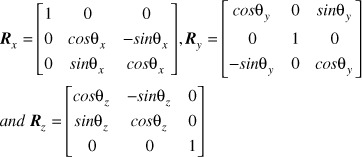 .
.
Whilst LGP applies these translations and rotations to the shot coordinates, they can equally be applied to any arbitrary stereotactic coordinate.
Assuming some patient setup ‘A’, any intracranial location described by coordinates PSTXref within CBCTSTXref can be described by coordinates PsetupA within CBCTsetupA via a transformation analogous to (1):
(2).
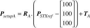
where RA and TA are the LGP-reported rotation and translation matrices derived from the co-registration of CBCTsetupA to CBCTSTXref. Similarly, if the setup then moves from ‘A’ to ‘B’, the new coordinates of the point P in setup ‘B’ are given by
(3).
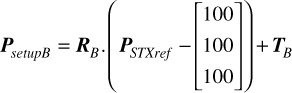
with RB and TB the LGP-reported rotation and translation matrices similarly derived from the co-registration of CBCTsetupB to CBCTSTXref. But in moving from setup ‘A’ to setup ‘B’ the magnitude of the displacement of the point P is simply given by:
(4).
Importantly, since it is the acquisition of CBCTsetupA that zeros the HDMM trace, the corresponding displacement of the nose marker between set ups ‘A’ and ‘B’, Dnose, is simply the HDMM reading at the time of CBCTsetupB. Therefore, for any pair of CBCT scans between which the nose marker remains on the patient, a relationship between nose displacement and intracranial target displacement can be derived simply from the displacement Dp (4) and the nose displacement Dnose taken from the HDMM reading at the time of the second CBCT scan. In the present work, that relationship is expressed as the ratio RD (5):
(5).
Materials and Methods
All results were collected from one of the centres (Leeds) using GK Icon™ running control system software version 11.0 and Leksell GammaPlan (LGP) version 11.0.1 or 11.0.3.
Patient inclusion
Any patient undergoing mask immobilised GK SRS at the collecting centre was considered eligible for this study. Of that population of patients, only those who had at least two CBCT scans within the delivery of a single fraction could be included due to the necessity of having paired CBCT scans available for analysis. Of that sub-set of patients, only those for who the nose marker or mask was not removed between paired CBCT scans could be included.
It is stressed that the Icon™ workflow necessitates one CBCT scan be acquired immediately prior to delivery of any treatment fraction. Additional CBCT scans are only required if the patient nose marker displacement cannot be returned below threshold following an HDMM-triggered treatment pause. No additional CBCT scans, that were not otherwise necessary for successful delivery of patient treatments, were acquired solely for the purpose of this study.
Patient target versus nose marker displacement ratio
For any instance of paired CBCT scans included in the study, the fluctuating HDMM reading throughout the duration of the second CBCT scan was observed at the GK control console and the minimum and maximum values during this scan were recorded. The mid-point of these two extreme values was then used as the value for Dnose.
For that same CBCT pair, the LGP-reported co-registration translations and rotations were applied (equations 2 and 3) to coordinates representative of the target volume centre(s) using MATLAB in-house written software. The coordinates chosen as representative of a target volume centre were those at the centre of the target’s corresponding dose calculation matrix within LGP. The displacement(s) of target centre(s), DP, were then calculated via equation 4. Thus, for each CBCT pair, the target-to-nose displacement ratio, RD, (equation 5) was calculated for each target in that patient’s treatment plan. Additionally, the differences between the LGP on-screen reported co-registration translations and rotations from CBCTsetupA and those from CBCTsetupB were calculated.
Variation throughout stereotactic space
The stereotactic coordinates at the centre of the treated target volumes represent only a small sampling of the extent of stereotactic space. In order to obtain a fuller, yet still clinically-relevant, range of stereotactic coordinates, the minimum and maximum values of x, y and z across all target volume centres included in this study was determined and a 32×32×32 3D grid of points uniformly distributed between these extremes (extended to the nearest 5 mm) was then constructed in MATLAB. This grid represents 32768 points in stereotactic space additional to the locations of the actual targets treated in practice.
For each of these 32768 grid points the displacement was calculated (equation 4); one 32×32×32 3D grid of displacements for each available CBCT pair. Using the HDMM-indicated nose displacements corresponding to each of these CBCT pairs, the displacement ratio RD of each point in each grid was then calculated. For any individual patient contributing more than one CBCT pair, the grids of displacement ratios from that patient were combined in order to determine the mean displacement ratio at each grid point for that particular patient. The result was one 32×32×32 3D grid of displacement ratios for each patient. These 3D grids of displacement ratios from each patient were then combined in order to determine the sample mean and standard deviation displacement ratio at each grid point, and so quantify how the displacement ratio typically varied over the clinically-relevant extent of stereotactic space. Further, the distribution of displacement ratios at each grid point was tested against a null hypothesis of a normal distribution using a Kolmogorov-Smirnov test at the 5% significance level. Finally, the 95% confidence limits for the population mean displacement ratio at each grid point were calculated.
Retrospective HDMM threshold review
Using the 32×32×32 grid of patient-averaged mean displacement ratio values,  , constructed above, 3D linear interpolation was performed in MATLAB in order to calculate the displacement ratio expectation value at the coordinates corresponding to each target volume (dose calculation matrix) centre included in this study. Using these expectation values, a hypothetically-acceptable HDMM threshold level was subsequently calculated for each target (rearranging equation 5) based upon an ‘acceptable’ level of maximum target displacement of 0.8mm. A value of 0.8mm was chosen since this is equivalent to the native pixel resolution of the MR images typically used for GK SRS treatment planning at the collecting centre and is, therefore, arguably within the uncertainty associated with target delineation in these images.
As a more conservative approach to determining hypothetically-acceptable HDMM threshold levels for each target volume, the same analysis was alternatively performed using the 3D grid of upper 95% confidence limit values.
Results
Patient inclusion
Analysis was performed on a total of 36 paired CBCT scans performed between December 2015 and June 2018. These paired CBCT scans originated from a total of 22 different patients, having a combined total of 41 target volumes (33 metastatic, 8 meningioma). Fractionation schedules were 25 Gy in 5 fractions (7 patients), 30 Gy in 5 fractions (10 patients) and 27 Gy in 3 fractions (5 patients). The total number of patients undergoing mask immobilised treatment at our centre during this same period was 99.
Of the 22 included patients three contributed 2 paired CBCT scans each, two contributed 3 CBCT pairs each, one contributed 4 pairs and one contributed 5 pairs. The remaining 15 patients contributed a single paired CBCT each.
Nose marker versus patient target displacement ratio
Figure 1 shows the relationship between the magnitude of the HDMM-indicated nose displacement and the magnitude of the CBCT-calculated target displacement for all patient target-volume/CBCT-pair combinations included in the study (n = 65; for the 36 analysed paired CBCT scans, an average of 1.81 targets included per scan). The line of unity is also included; points lying below this line correspond to instances in which a patient’s movement has resulted in their target(s) moving less than their nose. Error bars indicate the range of fluctuating HDMM values observed throughout the 30 second duration of the second CBCT scan (CBCTSetupB).
For all points included in Figure 1, Figure 2 shows the corresponding displacement ratio, RD, calculated. The mean(standard deviation) displacement ratio is 0.54(0.32). The maximum displacement ratio observed was 1.65.
Figure 1.
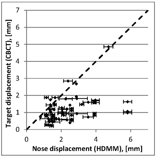
Target displacement determined from CBCT co-registration versus nose tip displacement determined from the HDMM system. Points lying below the line of unity (dotted line) correspond to instances where patient movement has led to targets displacing by an amount less than the nose tip. Error bars indicate the HDMM range during the second of the CBCT scan pairs.
Figure 2.
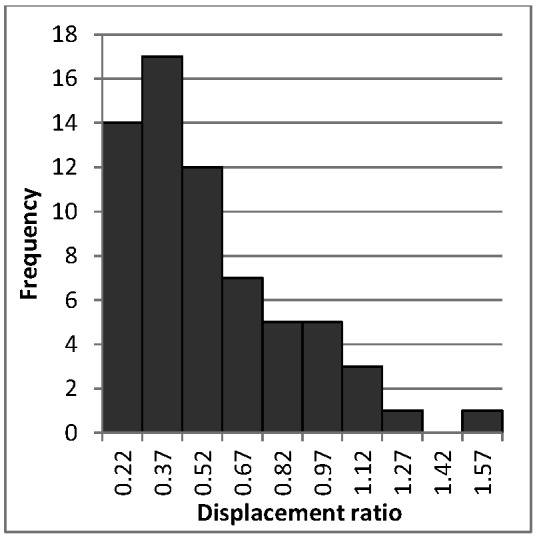
Calculated values of target-to-nose magnitude displacement ratio, RD, for all target/CBCT-pair combinations included in this study.
Across the 36 paired CBCT scans, the ranges of LGP on-screen reported co-registration differences, CBCTsetupB - CBCTsetupA were 2.14° to 1.26°, 1.85° to 1.28° and 1.22° to 1.53° for x, y and z rotations, respectively, and 0.52mm to 1.58mm, 1.22mm to 0.86mm, and 4.25mm to 1.43mm for x, y and z translations, respectively.
Variation throughout stereotactic space
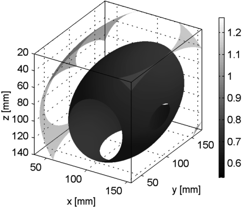
The extent of sampled stereotactic space ranged from 35mm to 155mm, 30mm to 170mm and 20mm to 140mm in the x, y and z directions, respectively, giving corresponding grid spacings of 3.75mm, 4.38mm and 3.75mm. The spatial variation of the mean displacement ratio, , over this extent is depicted in Figure 3, which shows the iso-surfaces corresponding to = 0.54, 0.77 and 1. These selected iso-surfaces represent: the mean displacement ratio calculated from our patients’ actual targets (above), the surface outside of which intracranial displacements typically exceed those of the nose (i.e. >1), and the mid-point between these two values. For only an extremely peripheral region at one corner of the sampled stereotactic space does exceed 1. Clinically, for a patient undergoing GK SRS in a mask, such a region is unlikely to be occupied by anatomy, only air. The volume inside the 0.54 displacement ratio iso-surface is 432cm3, corresponding to 21% of the total 2016cm3 sampled volume.
Figure 3.
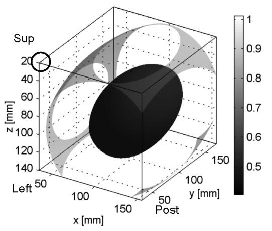
Spatial variation of mean target-to-nose displacement ratio  showing iso-surfaces corresponding to = 0.54, 0.77 and 1. The corner containing the iso-surface = 1 is circled.
Figure 4 alternatively depicts the same spatial variation of as x-y plane contour plots at levels z = 20, 44, 68, 92, 126 and 140 [mm] and allows for the clearer depiction of more numerous iso-levels.
The maximum displacement ratio in this 3D data set is 1.01. The minimum displacement ratio is 0.41 and corresponds to a point at coordinate (101,107, 90)mm. The mean(range) radial distance between this minimum point in the averaged data and the minimum points in the individual patients’ data is 55(18 to 117)mm. For three of the 22 patients was this distance 117mm, corresponding to the edge of the sampled volume (Figure 5), so indicating a further minimal point that lies outside the sampled extent of stereotactic space.
Figure 5.
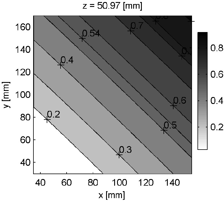
Contour plot of displacement ratios through plane z = 50.97mm for selected patient with minimum point lying on the edge of the sampled extent of stereotactic space.
For 32693 of the 32768 grid points (i.e. 99.8% of the grid points), the Kolmogorov-Smirnov test yielded a p-value of <0.05 for the null hypothesis of a normal distribution of displacement ratios. The standard deviation values associated with the 32768 values of are shown in Figure 6.
Figure 6.
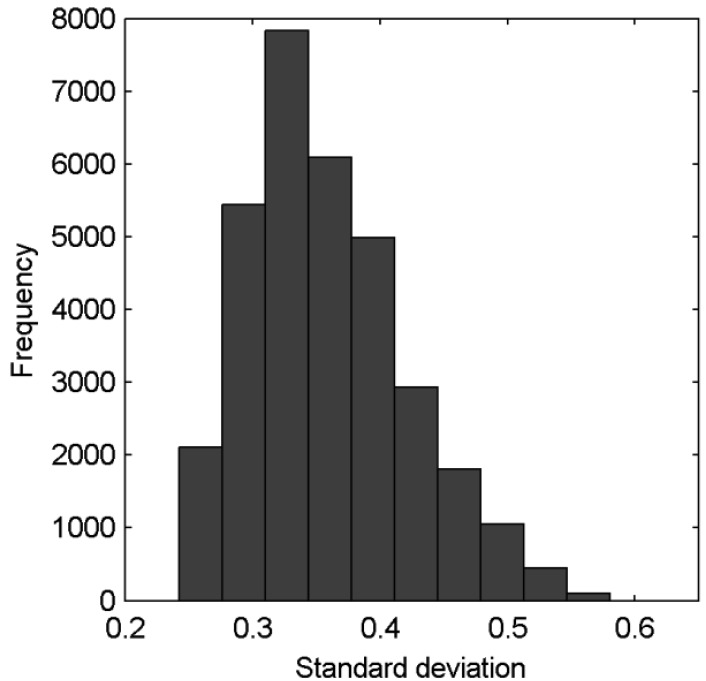
Standard deviations associated with the 32768 gridded values of .
Figure 7 shows the spatial variation of the population mean displacement ratio upper 95% confidence limit (UCL) and includes the iso-surfaces corresponding to UCL = 0.77 and 1. The maximum displacement ratio in this 3D data set is 1.27. The minimum displacement ratio is 0.54 and corresponds to a point at coordinate (97, 111, 90)mm. The UCL = 1 iso-surface occupies a more clinically-relevant central region within stereotactic space than does the = 1 iso-surface in Figure 3. Nevertheless, the volume of stereotactic space inside the UCL = 1 iso-surface - i.e. the volume inside of which intracranial anatomy typically displaces less than the nose at a 95% confidence level - still represents a substantial portion of the total sampled extent of stereotactic space; 1887cm3 of the total 2016cm3 sampled volume.
Retrospective HDMM threshold review
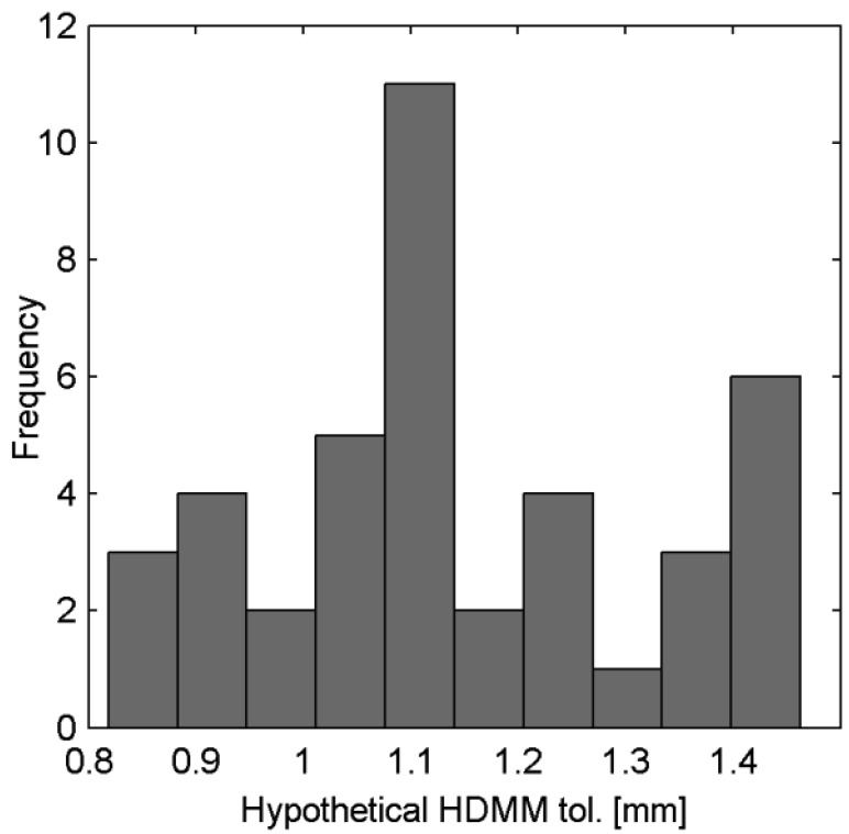
For the 41 target volumes included in this study, Figures 8 and 9 show the hypothetically-acceptable HDMM threshold levels calculated (assuming an allowed maximum target displacement up to 0.8mm) from interpolation of the 3D grid of and the 3D grid of UCL values, respectively. Based on the data, the median(range) hypothetically-acceptable HDMM threshold level of our 41 targets is 1.37(1.01 to 1.94)mm, and is greater than 1mm (our standardly-adopted value at present) for all targets. Based on the UCL data, the median(range) hypothetically-acceptable HDMM threshold level of our 41 targets is 1.10(0.82 to 1.46)mm, but lower than our current standard of 1.0mm for 9 of these targets.
Figure 8.

Hypothetically-acceptable HDMM threshold levels for the 41 targets in this study, calculated from 3D-interpolated values and assuming a maximum allowed target displacement of 0.8mm.
Figure 9.
Hypothetically-acceptable HDMM threshold levels for the 41 targets in this study, calculated from 3D-interpolated UCLvalues and assuming a maximum allowed target displacement of 0.8mm.
Figure 4.
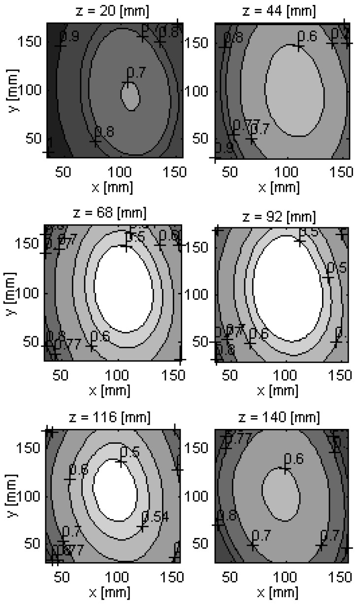
Spatial variation of mean target-to-nose displacement ratio, , showing the x-y plane contours corresponding to = 0.5 0.54, 0.6, 0.7, 0.77 0.8, 0.9 and 1. The corner containing the iso-surace = 1 is visible at level z = 20mm (superior-most level).
Discussion
The concept of image-guided frameless SRS with real time motion tracking is not new (e.g. [12,13]) and examples of its implementation using various alternative commercially-available solutions have been reported well before now (e.g. [14-16]). However previous attempts at frameless SRS on GK were not without issues [17] and so with the inclusion of an integral CBCT and the HDMM system, Icon™ has provided for the first time a practical solution for motion-tracked imaged-guided frameless SRS on GK. However, in regards to an appropriate choice for the HDMM threshold level there is little clinical evidence to guide the Icon™ user.
Figure 7.
Spatial variation of the target-to-nose displacement ratio upper 95% confidence limit (UCL), showing iso-surfaces corresponding to UCL= 0.77 and 1.
Nose marker versus patient target displacement
One important aspect pertaining to appropriate HDMM threshold level is the relationship between the displacement of intracranial anatomy and the surrogate displacement of the nose marker as indicated by the HDMM system. In a scenario where intra-fraction motion consists of pure translations the two are equivalent (assuming the head is a rigid body). In contrast, intra-fraction motion that includes any element of rotation will result in a non-equivalent relationship whose exact nature will depend upon the locations of the target and the nose, and their respective positions relative to the axes of rotation. In a study using an anthropomorphic phantom, intra-fraction movements having substantial contribution from y-axis rotations were found to result in displacements of certain intracranial target locations that exceeded those of the nose by up to 73% [8]. As is argued in that study, evidence indicating intracranial anatomy displacing less than the nose is desirable: if such a relationship could be guaranteed, an appropriate value for the HDMM threshold is simply the maximum intracranial displacement deemed acceptable, since the user could be certain the treatment would pause before such a displacement is exceeded. There is no data from our study that indicates that for real patients, intra-fraction motion is particularly dominated by rotations about the y axis.
In the phantom study, typical intracranial target displacements were indeed found to be smaller in magnitude than HDMM-indicated nose displacements: 43(38 to 48)% [mean(95% confidence interval)] smaller. Those results are comparable to the patient data we present in this study, which indicate a mean(standard deviation) displacement ratio of 0.54(0.32). Furthermore, our data is also comparable to that from a study of a prototype HDMM system tested on a linac: for four patients fixed in a mask the average intracranial target displacement was 47% less than optically-tracked nose tip movement (0.27mm versus 0.51mm, respectively; a ratio of 0.53) [9].
It is highlighted that our study presents data collected from real patients rather than a phantom, and represents a larger number of patients (22 rather than 4) undergoing treatment on the commercial implementation of the HDMM system on GK itself, rather than a prototype system on a linac. Consequently, this study provides strong support to those two prior studies that concluded intracranial anatomy displaces by a magnitude typically around half that of the nose. Nevertheless, both these prior studies, as well as the data presented here, indicate that the desirable relationship in which intracranial displacement is less than nose displacement cannot be guaranteed in all cases. Furthermore, even if such a relationship could be guaranteed, an HDMM threshold simply set equal to the maximum acceptable intracranial displacement does not necessary represent a choice that is optimal. Setting a threshold represents compromising between maintaining an acceptable level of geometric accuracy and the ability to deliver the treatment without prohibitively excessive interruptions to irradiation or an unjustifiably high concomitant imaging dose. In instances where the target-to-nose displacement ratio is particularly small, a relatively large HDMM threshold level may be considered more optimal, since such a choice might still maintain acceptable geometric accuracy whilst also reducing the risk of excessive HDMM-triggered gating events.
Variation through stereotactic space
The novel analysis of real patient co-registration and HDMM data presented in this study represents an attempt to generate data to assist in identifying cases where HDMM threshold might safely be increased, based upon the location of the target in stereotactic space. The smallest mean displacement ratio values lie quite centrally within the sampled extent of stereotactic space, possibly indicating that head rotations tend to occur around a similarly central location or, alternatively, that the location of minimum displacement ratio varies widely from patient to patient and simply averages close to a central point. Nevertheless, this observation is in contrast to the previously-presented phantom data [8] which indicated the likely point of rotation was close to the occiput depression in the head rest. The difference between that phantom study and this study exemplifies the importance of using data originating from real patients undergoing true biomechanical movements during mask-immobilised GK SRS, as opposed to that from the simulated movements of a phantom.
Based upon the 3D grid of mean displacement ratios generated from our patient data, the retrospective review of threshold levels for the 41 target volumes included in this study suggest a median HDMM threshold level of 1.4mm might have been acceptable. Whilst it is acknowledged that this is based upon a somewhat dubious assumption that a displacement of the target up to a maximum of 0.8mm is ‘acceptable’, nevertheless the example serves to highlight the potential utility of the data generated in this study. Absent of any evidence to guide us otherwise, at the collecting centre an HDMM threshold of 1.0mm is routinely used. Of the 36 paired CBCT-scans included in this study, six (17%) were acquired whilst the HDMM reading was below the 1.4mm value during the second scan. Furthermore, given only a small proportion of HDMM gating events actually necessitate the acquisition of a second CBCT scan, this likely corresponds to the potential of a more substantial reduction in HDMM-triggered treatment interruptions.
Study limitations and future work
Of course, the hypothetically-acceptable HDMM threshold levels presented here are based only upon mean target-to-nose displacement ratio data. For any given individual patient’s target(s), the actual displacement ratio could be substantially greater than the mean ratio indicated at that location. Greater confidence that the hypothetical HDMM thresholds would not be set inappropriately high could be gained by basing them not upon sample mean displacement ratio data, but other statistics derived from the 3D data. In this study, the upper 95% confidence limit for the population mean has been chosen as a more conservative estimate, but alternative statistics could equally be chosen, depending upon the degree of caution required. Using our criteria for a conservative estimate, the median threshold level would have been 1.1mm rather than 1.4mm for our 41 targets, which still represents a small increase from the currently adopted 1.0mm standard. Prospectively comparing predicted target-to-nose displacement ratios to actual target-to-nose displacement ratios of future patients will provide insight into the quality of our data and analysis. Currently our analysis is based only upon a relatively small single-centre dataset.A larger multicentre dataset would likely be beneficial.
The other important aspect pertaining to appropriate HDMM threshold is the relationship between target (and critical structure) displacement and the resulting impact upon the delivered dose. Careful simulation of anatomical displacements would be needed in order to investigate how intra-fraction motion during mask-based GK SRS impacts upon delivered dosimetry. Whilst simulations of intra-fraction motion on GK have been performed previously [18,19] they are not necessarily representative of continually fluctuating displacements typically observed for patients immobilised in an Icon™ mask. Whilst an attempt at performing any such dosimetric analysis is well beyond the scope of the current work, it offers much opportunity for future investigation.
The current study limits itself to presenting only magnitude displacement data.The ability to obtain directional data from the HDMM systemand to subsequently relate this to the direction of intracranial displacement from CBCT would provide further insight into the relationship between nose and target intra-fraction motion, and may help inform the use of margins during treatment planning. However, in its current commercial implementation the HDMM system does not provide readily-available access to directional data.
Conclusions
A method for relating the magnitude of intracranial target displacement to the magnitude of a nose marker displacement, previously validated with a phantom, has been successfully implemented to determine that same relationship for real patients undergoing mask-immobilised GK SRS at a single centre. Our data - consisting of 41 target volumes from 22 patients - supports the conclusions of earlier smaller phantom- and linac-based studies that intracranial targets typically displace by a magnitude approximately half that of the nose. Nevertheless, both our data and that of those previous studies indicate that cases exist in which target displacement exceeds that of the nose.
In this study we have presented a novel analysis of our patient co-registration and HDMM data in order to construct a 3D grid of points describing how the relationship between target and nose displacement typically varies throughout a clinically-relevant extent of stereotactic space. A conservative analysis indicates that the desirable relationship in which targets displace less than the nose occupies a substantial central portion of the total sampled extent. Using less conservative analysis, target displacement exceeds nose displacement in only the most extreme - and clinically irrelevant - corner of the sampled space. Using this data it has been possible to calculate hypothetically-acceptable HDMM threshold levels for our 41 target volumes. Based upon an assumed maximum allowed displacement of 0.8mm, our data suggest that an average HDMM threshold of 1.4mm may have been appropriate for these 41 volumes, as compared to the 1.0mm threshold currently adopted as standard the collecting centre. Whilst this indicates the potential for increasing thresholds depending upon target location, it is acknowledged that truly informed choice of HDMM threshold relies not only upon insight into the relationship between nose and target displacement, but also upon an understanding of how target displacement impacts upon delivered doses. Whilst outside the scope of the current work, dosimetric evaluation of intra-fraction motion during mask-based GK SRS offers much opportunity for future investigation.
Acknowledgements
Authors’ disclosure of potential conflicts of interest
Gavin Wright, Jannie Schasfoort and Natalie Harrold report attendance at Icon user group meetings and hosted by Elekta, Gavin Wright additionally reports providing consultation services to Elekta for which his employer has received a fee. Paul Hatfield report receiving personal fees from Nova Healthcare, the provider of the Gamma Knife SRS service at the Leeds Cancer Centre. No other conflicts of interest are reported.
Author contributions
Conception and design: Gavin Wright, Jannie Schasfoort, Natalie Harrold, Peter Bownes
Data collection: Gavin Wright, Paul Hatfield, Natalie Harrold, Peter Bownes
Data analysis and interpretation: Gavin Wright, Jannie Schasfoort, Natalie Harrold
Manuscript writing: Gavin Wright, Jannie Schasfoort, Natalie Harrold, Paul Hatfield, Peter Bownes
Final approval of manuscript: Gavin Wright, Jannie Schasfoort, Natalie Harrold, Paul Hatfield, Peter Bownes
References
- 1. Elekta Instrument AB. Design and performance characteristics of a Cone Beam CT system for Leksell Gamma Knife® Icon™. White Paper 2015, Stockholm, Sweden. [Google Scholar]
- 2. Elekta Instrument AB. High Definition Motion Management - enabling stereotactic Gamma Knife® radiosurgery with non-rigid patient fixations. White Paper 2015, Stockholm, Sweden. [Google Scholar]
- 3. Stieler F, Wenz F, Abo-Madyan Y, Schweizer B, Polednik M, Herskind C, Giordano FA, Mai S. Adaptive fractionated stereotactic Gamma Knife radiotherapy of meningioma using integrated stereotactic cone-beam-CT and adaptive re-planning (a-gkFSRT). Strahlenther Onkol 2016;92(11):815-819; doi: 10.1007/s00066-016-1008-6 [DOI] [PubMed] [Google Scholar]
- 4. Elekta Instrument AB. Accuracy of co-registration of planning images with Cone Beam CT images. White Paper 2015, Stockholm, Sweden. [Google Scholar]
- 5. Elekta Instrument AB. Automatic positional delivery correction using a stereotactic CBCT in Lekesell Gamma Knife® Icon™. White Paper 2015, Stockholm, Sweden. [Google Scholar]
- 6. Sarfehnia A, Ruschin M, Chugh B, Yeboah C, Becker N, Cho YB, Lee Y. Performance characterization of an integrated cone-beam CT system for dedicated gamma radiosurgery. Med. Phys. 2018;29. doi: 10.1002/mp.13073. [Epub ahead of print] [DOI] [PubMed] [Google Scholar]
- 7. Blake S, Winch L, Appleby H. Initial experience with the Elekta Leksell Gamma Knife Icon system: commissioning, QA and workflow, Radiotherapy and Oncology, 2016;119: S921. [Google Scholar]
- 8. Wright G, Harrold N, Hatfield P, Bownes P. Validity of the use of nose tip motion as a surrogate for intracranial motion in mask-fixated frameless Gamma Knife® Icon™ therapy, Jour. of Radiosurgery and SBRT, 2017;4(4):289-301 [PMC free article] [PubMed] [Google Scholar]
- 9. Chung C, Li W, Bootsma G, Cho Y, von Schultz O, Carlsson P, Jaffray D. Clinical Evaluation of a Novel Thermoplastic Mask System With Intrafraction Motion Monitoring Using IR Tracking and Cone Beam CT for Gamma Knife Radiosurgery, Int. J. Radiation Oncology Biol. Phys. (Suppl) 2014;9(1): S848. [Google Scholar]
- 10. Studholm C, Hill DLG, Hawkes DJ. An overlap invariant entropy measure of 3D medical image alignment. Pattern Recognit 1999;32(1):71-86 [Google Scholar]
- 11. Maes F, Collignon A, Vandermeulen D, Marchal G, Suetens P. Multimodality image registration by maximization of mutual information. IEEE Trans Med Imaging. 1997. 16(2):187-98. [DOI] [PubMed] [Google Scholar]
- 12. Murphy MJ, Cox RS. The accuracy of dose localization for an image-guided frameless radiosurgery system, Med Phys 1996;23(12):2043-2049 [DOI] [PubMed] [Google Scholar]
- 13. Sweeney R, Bale R, Vogele M, Nevinny-Stickel M, Bluhm A, Auer T, Hessenberger G, Lukas P, Repositioning accuracy: comparison of a noninvasive head holder with thermoplastic mask for fractionated radiotherapy and a case report. Int. J. Radiat. Oncol. Biol. Phys. 1998;41:475-483. [DOI] [PubMed] [Google Scholar]
- 14. Takakura T, Mizowaki T, Nakata M, Yano S, Fujimoto T, Miyabe Y, Nakamura M, Hiraoka M. The geometric accuracy of stereotactic radiosurgery using a 6D robotic couch system. Phys. Med. Biol. 2010;55(1):1-10 [DOI] [PubMed] [Google Scholar]
- 15. Gevaert T, Verellen D, Engels B, Depuydt T, Heuninckx RN, Tournel K, Duchateau M, Reynders T, De Ridder M, Clinical Evaluation of a Robotic 6-Degree of Freedom Treatment Couch for Frameless Radiosurgery. Int. J. Radiat. Oncol. Biol. Phys. 2012;83(1):467-474. [DOI] [PubMed] [Google Scholar]
- 16. Adler JR, Chang SD, Murphy MJ, Doty J, Geis P, Hancock SL. The Cyberknife: A Frameless Robotic System for Radiosurgery. Stereotact. Funct. Neurosurg. 1997;69:124-128 [DOI] [PubMed] [Google Scholar]
- 17. Ruschin M, Nayebi N, Carlsson P, Brown K, Tamerou M, Li W, Laperriere N., Sahgal A., Cho Y., Ménard C, Jaffray D. Performance of a novel repositioning head frame for Gamma Knife Perfexion and image-guided linac-based intracranial stereotactic radiotherapy. Int. J. Radiation Oncology Biol. Phys. 2010;78(1):306–313. [DOI] [PubMed] [Google Scholar]
- 18. Reiner B, Bownes P, Buckley D, Thwaites D. Quantifying the trigger level of the vacuum surveillance system of the gamma-knife eXtend™ positioning system and evaluating the potential impact on dose delivery, Jour. of Radiosurgery and SBRT 2016;4(1):31-42. [PMC free article] [PubMed] [Google Scholar]
- 19. Reiner B, Bownes P, Buckley D, Thwaites D. Quantifying the effects of positional uncertainties and estimating margins for Gamma-Knife® fractionated radiosurgery of large brain metastases, Jour. of Radiosurgery and SBRT 2017;4(4):275-287. [PMC free article] [PubMed] [Google Scholar]