Abstract
Current conventional clinical OCT systems image either only the anterior or the posterior eye during a single acquisition. This localized imaging limits conventional OCT’s use for characterizing global ocular morphometry and biometry, which requires knowledge of spatial relationships across the entire eye. We developed a “whole eye” optical coherence tomography system that simultaneously acquires volumes with a wide field-of-view for both the anterior chamber (14 x 14 mm) and retina (55°) using a single source and detector. This system was used to measure retinal curvature in a pilot population and compared against curvature of the same eyes measured with magnetic resonance imaging.
1. Introduction
Optical coherence tomography (OCT) has revolutionized clinical observation of the eye since its inception [1] and is an indispensable part of the modern ophthalmic practice. Part of OCT’s appeal is its ability to rapidly provide non-contact, high resolution, three-dimensional (3D) anatomical information about the imaged eye [2–5]. If these 3D OCT representations of the eye covered both the anterior and posterior eye, then it should be possible to use OCT in lieu of a variety of other imaging devices to characterize ocular biometry and morphometry [6–9]. Ocular biometry and morphometry are important tasks in clinical practice such as for modern cataract surgery planning (currently using multi-modal partial coherence interferometry and keratometry [10,11]) or for research applications such as for correlating myopia and eye shape (currently using magnetic resonance imaging [12,13]). In this latter research application, MRI has been used to show that pathologic myopia is correlated with asymmetries in posterior eye shape; translation of these findings to routine clinical use would be substantially aided if OCT could be used in lieu of MRI. Early efforts to examine ocular shape with OCT have been performed (e.g. Shinohara, et al. [14], Ohno-Matsui, et al. [15], among others); however the shape analysis has been restricted to qualitative descriptors of the morphometry with limited comparison to MRI due to disparities in the separate and distinct qualitative descriptors used for each modality. Quantitative analysis of retinal or ocular shape using OCT has been limited owing to multiple optical distortions inherent to posterior segment OCT that alter the image of the posterior eye such that the image is not at 1:1 copy of anatomical morphometry; knowledge of the scanning system and the whole eye is required to remove these distortions to recreate the actual shape of the imaged posterior eye to allow for quantitative analysis from OCT [16–19]
Though “whole eye OCT” has been demonstrated for ocular biometry and morphometry in animal models with relatively small eyes [20,21], current- research and clinical OCT systems image only the anterior or posterior of the human eye fully during a single acquisition. This localized imaging limits conventional OCT’s use in human subjects for characterizing global ocular morphometry and biometry which requires knowledge of spatial relationships across the entire eye.
The limited localized imaging in human eyes is due to technical and optical constraints which limit OCT’s ability to image the human eye as a whole. One constraint is the depth or axial range of OCT. As an interferometric imaging technique, the detected signal in OCT is a result of the interference of path length matched light from the sample and reference arms. In a time domain OCT system, the reference arm could be stepped across the entire approximately 23 mm depth of the eye so that sample reflectors from the anterior eye all the way to the posterior eye would be within a coherence length of the reference arm to produce a signal for each sample reflector at each step. However, moving the reference arm across this large distance came at the expense of increased scan time (hence increasing motion artifacts) and decreased sensitivity compared to more modern Fourier domain (FD) systems [22–24]. Fourier domain systems are much faster with better sensitivity but still suffer from sensitivity roll-off, wherein reflectors spatially distant from the corresponding reference arm position (higher frequencies in Fourier space) are attenuated. The image depth is further halved by the presence of the complex conjugate artifact in FD processing. For the spectrometer designs currently employed by the majority of clinical FD OCT systems, the axial range of these systems is typically limited to approximately 2 mm – an order of magnitude smaller than the axial length of the human eye.
The recent advent of sources with unique coherence length properties have overcome some of these depth limitations. Wavelength tunable vertical cavity surface emitting lasers (VCSEL) with long coherence lengths can have axial imaging ranges on the order of a meter [25,26]. Using a VCSEL source, “whole eye OCT” for ocular biometry length measurements has been demonstrated [27]. However, though this source overcame the interferometric limitations of imaging the whole eye, the demonstrated imaging system did not overcome the optical limitations of imaging over the length of the eye. In described VCSEL systems, the anterior segment can be fully visualized but only a tiny area on the retina was imaged from the initially telecentric light passing through the anterior eye optics. This imaging topology has also been used in a spectrometer based system that switched between reference arms to increase effective imaging depth but still with the same limitation in field of view of the posterior eye [28]. Producing useable OCT scans of both the anterior and posterior eye comparable to a dedicated OCT system for each region requires consideration of system depth of focus over the eye length as well as different scanning requirements for each region of the eye: telecentric for the anterior eye and collimated for the posterior eye which needs to pass first through the anterior eye optics.
Aside from combining two independent systems into a shared set of terminal optics [29,30], “whole eye OCT” with both anterior and posterior segment B scans comparable to dedicated OCT systems for each has been shown using a single swept source by either switching between imaging planes [31,32] or polarization multiplexing [33–35]. With polarization multiplexing, optical limitations are addressed by splitting the light into orthogonal polarization states and creating a dedicated anterior and posterior eye optical system channel for each polarization. In these early implementations, though, the field-of-view in the posterior eye only encompassed a small region around the fovea (approximately <20°) limiting their use for full ocular morphometry studies.
Building on the polarization encoded optical design and utilizing a coherence revival detection scheme, in this work we describe the development of the first whole eye OCT system with wide field of view OCT for both the anterior and posterior eye simultaneously.
2. Methods
2.1 Wide-field whole eye OCT system design
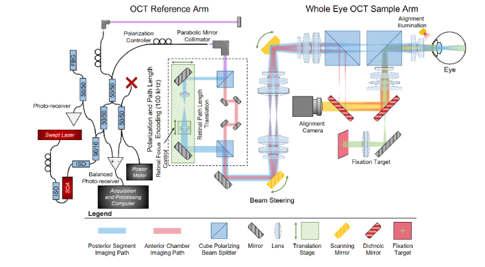
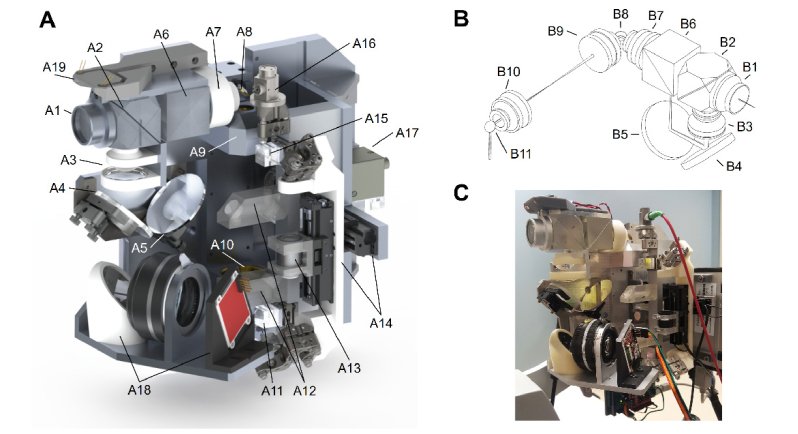
We designed a custom whole eye OCT system (Fig. 1) using custom optics and optomechanics (Fig. 2) to allow for wide-field imaging of both the anterior chamber and posterior segment (retina) utilizing light in the 1050 nm water window [36,37]. Additionally, we utilized the Polans schematic eye model in our optical design [38,39] (ZEMAX model available in [39]). We used the Polans eye model because it was developed specifically for accurate optical performance not only in the central posterior segment but also in the peripheral posterior segment as well which is important given our wide-field design. To multiplex information from both the anterior chamber and posterior segment into every A-scan, we designed the system to utilize orthogonal linear polarizations for each imaging channel, allowing imaging light for the anterior chamber to follow a different dedicated optical path than the posterior segment [34]. Taking advantage of the coherence revival effect present in some swept-source lasers, which creates multiple spatial opportunities for interference at multiples of the laser cavity length [40,41], we designed the posterior eye imaging path length to be the same length as the OCT reference arm and the anterior eye imaging path length to be equal to the reference arm length plus one cavity length of the laser.
Fig. 1.
Whole eye OCT system schematic. Created using custom optics and optomechanics. Polarization was utilized to separate the imaging channels. Translation stages prior to the scanning galvanometers were placed such that without changing any optics utilized for imaging the anterior chamber, they allow for control and optimization of posterior segment imaging including eye length and Diopter focus control. A semiconductor optical amplifier (SOA) with optical isolators (ISO) was used to increase source output power.
Fig. 2.
Custom whole eye sample arm optical and optomechanical design. A) Solidworks rendering of sample arm optics and optomechanics. Starting from final imaging objective and working back to OCT input fiber collimator A1: Air-spaced achromatic doublet; A2: Wire-grid polarizing beam splitter cube to recombine anterior chamber and retinal imaging paths; A3: Pair of air-spaced achromatic doublets; A4: Dichroic mirror allowing for visible light of fixation target (A18) to pass through; A5: Dichroic mirror allowing 851 nm light of iris camera (A17) LEDs (A19) to pass through; A6: Dielectric polarizing beam splitter cube to separate anterior chamber and retinal imaging paths; A7: Air-spaced achromatic triplet; A8: Superior-inferior scanning mirror; A9 and A10: Pair of air-spaced achromatic triplets to image the temporal-nasal scanning mirror (not visible) on to the superior-inferior scanning mirror (A8); A11: Dielectric polarizing beam splitter cube to recombine anterior chamber and retinal imaging paths; A12: Optical path length delay for anterior chamber path; A13: Achromatic doublet on mechanized stage to allow for Diopter correction in the retinal imaging path independently of the anterior chamber path; A14: Mechanized stage that independently adjusts the optical path length of the retinal imaging path to account for various ocular axial lengths; A15: Dielectric polarizing beam splitter cube that separates anterior chamber and retinal imaging paths; A16: Parabolic mirror collimator; A17: Iris imaging camera; A18: OLED Fixation target and relay optics; A19: 851 nm illumination LEDs for iris camera; B) Sample arm ZEMAX optical design drawing. Drawing includes all optics following polarization path length encoding optics (see Fig. 1). Beam path shown for the central anterior chamber imaging path. Retinal imaging transmits through both beam splitters (B6 and B2). B1-B10 correspond directly to A1-A10 with B11 showing the location of the temporal-nasal scanning mirror hidden in A. Here, the scanning mirror 4-F imaging telescope (B8-B11) was rotated 90° for visualization purposes. C) Photograph of wide-field whole eye OCT sample arm as implemented.
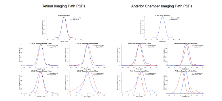
We based the wide-field whole eye OCT system around a spectrally balanced reflective interferometer [34]. The OCT reference arm was completely reflective using an off-axis parabolic mirror for collimation and a mirror to return light to the fiber. This was done to limit possible reflections from lens surfaces which could introduce unintended imaging artifacts at other coherence revival peaks. In the sample arm (Fig. 2), polarizing cube beamsplitters and motorized translation stages prior to the scanning galvanometers allowed for control and optimization of the posterior segment imaging path. One translation stage (MM-3M-FOS-X-TR2-SPRS2-AB National Aperture, Inc.) was utilized to adjust optical path length of the retinal imaging optics to match the subject’s eye length to the reference arm length. The second lens of the beam expander in the retinal path of the polarization encoding portion of the sample arm was mounted to a translation stage (MM-3M-FOS-X-TR3-SPRS2, National Aperture, Inc.), thus providing Diopter focus control to correct for patient defocus without adjusting any optics utilized for imaging the anterior segment. At the 0 Diopter position of the control stage, this resulted in a retinal imaging beam diameter of 2.2 mm at the ocular pupil. The co-linear anterior chamber and posterior segment imaging beams were scanned across the X and Y transverse directions through the use of orthogonal scanning galvanometers. The first galvanometer was imaged onto the second galvanometer through the use of a 4F telescope. This geometry was used to minimize distortion and pupil wobble at the image plane over a more conventional offset orthogonal galvanometer scanning pair. The second mirror angle rotated the polarization coordinate system such that the posterior segment beam was P-polarized and the anterior chamber beam was S-polarized. The final polarizing beamsplitter consisted of a wire grid polarizer cemented between two custom prisms. This OCT system design resulted in a posterior segment field of view of 55° relative to the posterior nodal point of a schematic model eye [38], and an anterior chamber field of view of 14 x 14 mm. Figure 3 provides point spread functions (calculated using the Huygens’ wavelet method in ZEMAX) for both the retinal and anterior chamber paths at selected scan points.
Fig. 3.
Point spread functions for both retinal and anterior chamber imaging paths along both the temporal-nasal and superior-inferior imaging planes. The tangential (along the temporal-nasal plane) PSFs are in red and sagittal (along the superior-inferior plane) PSFs are in blue. Shown are the central, half-way, and maximum positive scan positions for each imaging path.
The anterior segment path included two separate dichroic fold mirrors to wavelength multiplex other devices that aid patient alignment. To improve patient fixation, we integrated an OLED screen into the system through the use of a hot mirror to provide a multi-color, dynamic retinal fixation target. The fixation target consisted of a cross-hair (either green marker on red background or red marker on black background) that could be placed to align for the visual axis, the optical axis of either eye, or elsewhere to target an area of interest. Patient alignment by the operator was aided with live video feedback of the iris and pupil diffusely illuminated by 851 nm LEDs on the anterior eye.
We demonstrated the whole eye system design with a 100 kHz a swept-source laser (Axsun Technologies) centered at 1045 nm with 100 nm of bandwidth. A semiconductor optical amplifier (SOA) was used to increase output optical power of the laser such that the power at the eye was limited by ANSI safety standards (as described in Section 2.3). A balanced photodetector (PDB481C-AC, Thorlabs) was used to detect the OCT interferograms which were digitized utilizing 12 bits at 1.8 GSamples/s (ATS9373-D6, AlazarTech). We used the back reflection from a fiber Bragg grating and a photodiode to generate a start of sweep trigger. The clock signal generated by the laser was acquired and interpolated to generate 5184 samples per laser sweep. This provided an imaging depth range of 14.1 mm, with the posterior segment occupying the first 4.1 mm and the anterior chamber (placed at a coherence revival peak) occupying the latter 10 mm. Dispersion compensation was applied independently to both the anterior segment and posterior segment images to correct for differences in imaging paths and artifacts due to coherence revival [34]. The spectrum of each A-scan was windowed utilizing a scaled Slepian window to minimize ringing within the image.
2.2 Ocular measurements
By utilizing the subject’s ocular axial length, the distance of the subject from the imaging system, and the optical design of the system, we corrected the optical distortions imparted on the retinal image due to the subject and imaging optics solely from our wide-field whole eye OCT data [18]. Using this wide FOV retinal image with correct spatial dimensions, we measured the posterior segment curvature using the four step process described below. All quantitative measurements were performed on volumes using a repeated radial scan pattern and processed as described in Section 2.1.
2.2.1 Segmentation of the ocular structures
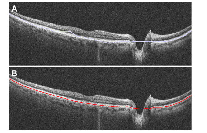
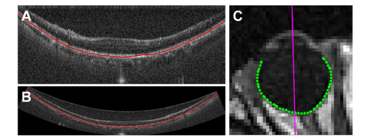
Delineating the retinal pigment epithelium (RPE) was the first step in quantifying retinal curvature. Repeated radial volumes consisting of 18 averaged B scans per volume (providing a radial sampling every 10°) were analyzed. The RPE was first manually estimated in each radial scan (Fig. 4(A)). This rough manual segmentation then served as a guide line for finer automated graph-theory based segmentation (Fig. 4(B)) [42]. The manual segmentation line was used to provide bounds for the automatic segmentation search region, 25 pixels above and below the manual estimation. These boundaries simplified segmentations, especially in regions around the optic nerve where the RPE was not present. For anterior chamber optics, we manually segmented the corneal epithelium and endothelium. We corrected the endothelial segmentation for refraction distortions, calculated the central corneal thickness (using ng-cornea = 1.388 [43,44]), and estimated the radius of curvature for both corneal surfaces [44–46]. Once all radial images were segmented, the segmentations were then stored and used in Section 2.2.4 for posterior segment curvature calculations following corrections for system and subject distortions.
Fig. 4.
Segmentation of the retinal pigment epithelium along a single averaged radial scan with the optic nerve head present. A) Initial rough manual segmentation of the RPE. This segmentation serves as a guide line for an automated segmentation algorithm and only needs to be a rough estimate. B) Automatic graph-theory based segmentation of the RPE using the pilot guide from A.
2.2.2 Eye-to-system distance and ocular axial length calculations
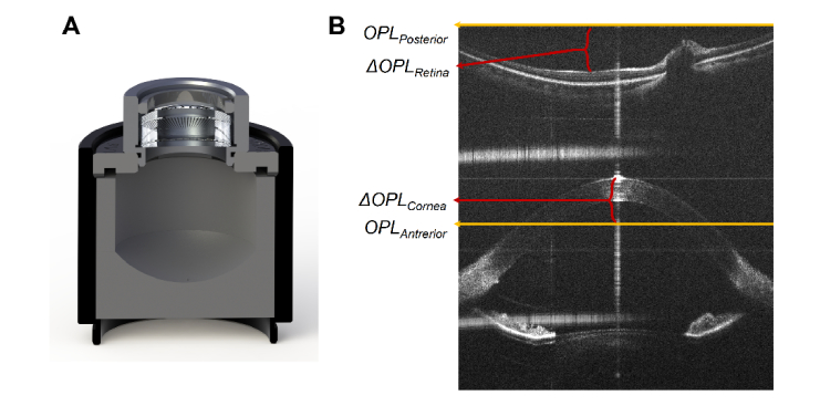
Using the simultaneously acquired anterior and posterior segment images, we calculated two values: 1) the distance between the apex of the cornea of the subject and the imaging system and 2) the subject’s ocular axial length (Fig. 5). As a calibration step for both values, prior to patient imaging, the axial pixel pitch (µm/pixel) was measured and recorded. For areas of the image containing retina, the pixel pitch was multiplied by the group index of refraction for balanced salt solution as a substitute for vitreous (ng-vitreous ≈ng-bss = 1.344) [43].
Fig. 5.
Ocular axial length measurement. A) Solidworks rendering of phantom eye model for axial length calibration B) Full-depth averaged radial scan with dispersion compensation optimized for retinal path. OPLAnterior corresponds to the location of the anterior chamber image plane and 1st order coherence revival term within the B-scan (located in the inferior half of the image). OPLPosterior corresponds to the retinal imaging plane and the 0th order coherence revival term (located in the superior half of the image). The ΔOPLRetina and ΔOPLCornea terms are used for biometry and correspond to the distance of each structure to their relative image plane. The ΔOPLRetina takes into account the index of refraction of the vitreous (ng-vitreous ≈1.344).
As an initial calibration step to calculate the eye-to-system distance, the distance of the anterior chamber imaging plane was initially located by determining the pixel depth that best resolved an imaged USAF 1951 test chart. That depth value was then related to the physical distance described within our ZEMAX optical design. This value corresponded to system OPLAnterior.
Calibration for ocular axial length utilized a custom phantom eye model that consisted of a single achromatic lens (AC127-025-C; Thorlabs, Inc.) and a custom 3D printed plastic target, with a radius of curvature of 13 mm, mounted at a fixed distance from the lens (Fig. 5(A)). This fixed distance corresponded to the focus of the lens and was approximately equal to the optical path length of a human eye [47]. We imaged the phantom eye such that the apex of the achromatic lens was placed at the pixel depth that corresponded with OPLAnterior By using this known optical system we were able to relate OPLPosterior (DC or a pixel depth of 0) to OPLAnterior as a function of reference arm position, position of the retinal path length control stage in the sample arm, and the respective optical path lengths of our system optical model.
To calculate eye-to-system distance (ΔOPLCornea) and ocular axial length for human imaging, a B-scan with the subject’s fovea was located within the radial volume set, see Fig. 5(B). For ΔOPLCornea, we first manually identified the pixel depth of the corneal apex within the anterior chamber region of the B-scan. ΔOPLCornea was obtained by converting this pixel value to depth and subtracting from system OPLAnterior. Because the gap between the corneal apex and the system was air, we assumed a refractive index of ng_air = 1. A subject’s ocular optical axial length was calculated as follows. The pixel location of the bottom of the foveal pit within the B-scan was manually recorded. ΔOPLRetina was obtained by converting this pixel value to depth (and accounting for nvitreous) and was added to system OPLPosterior. The difference between ΔOPLCornea and ΔOPLRetina corresponds to the ocular optical axial length. To calculate the physical axial length, we utilized the corneal thickness measured in Section 2.2.1, the optical path length of the Polans eye model lens in phakic subjects or a model acrylic intraocular lens in pseudophakic subjects, and assume the rest of the optical path length was either aqueous or vitreous which we modeled as balanced salt solution with a group index of ng-bss = 1.344.
2.2.3 Ray trace model
For each subject, we corrected the system and subject optical distortions present within the retinal portion of the OCT image using methods we have previously described [18]. We modeled each subject’s imaging session in ZEMAX using the subject’s calculated information from Sections 2.2.1 and 2.2.2 (Fig. 6). The model included our optical design, the distance of the subject to the imaging system, the subject’s corneal surface curvatures, corneal thickness, and the subject’s measured ocular axial length. For phakic subject’s we utilized the Polans eye model gradient lens and for pseudophakic subject’s we used a modeled acrylic intraocular lens within the model. The ZEMAX optomechanical model included both scanning mirror angular positions, which allowed for simulation of beam scanning within the model. A script was used to simulate a scan of the retinal beam over the same angular range as an imaged B-scan or volume. The script recorded both the position and angle of the beam chief ray relative to the ocular optical axis as a function of scanning mirror angular position.
Fig. 6.
ZEMAX ray trace model of individual subject where above descried parameters were adjusted A) Retinal imaging path of a single scan position with subject eye modeled using previously calculated subject position and axial length. A script moves the beam within the model and the chief ray vector position and angle at the retina is calculated and stored. B) Zoom of modified Polans eye model using axial length of the subject.
2.2.4 Retinal curvature estimation
We estimated retinal curvature within OCT images using the RPE segmentation found as described in Section 2.2.1 and correcting the optical distortions present within that segmentation using the modeling done in Section 2.2.3 [18]. Conventional ophthalmic OCT images are typically shown as rectangular arrays of sampled pixels with A-scans oriented vertically adjacent to one another and not scaled for physical dimensions. While this convention is often acceptable for qualitative analysis in the presence of a pathology, variations in both the optics of subjects and imaging systems from various manufacturers make quantitative comparisons untenable using uncorrected images. Previous efforts to correct for system subject distortions have shown the ability for quantitative morphometric analyses to be performed on in vivo OCT images [9,46,48].
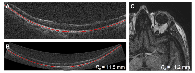
We assumed that the modeled chief-ray of the scanned beam at a given angular mirror position was co-linear with the acquired A-scan at the same angular position. Using the optical model, we transformed and scaled each A-scan to match the angle and position of the chief ray as well as to have isotropic scaling of physical dimensions. This can be seen in Fig. 7 with the uncorrected image in Fig. 7(A) and the corrected image in Fig. 7(B). These corrections were also applied to the RPE segmentation. We fit a circle to the RPE segmentation for each dewarped radial and used the mean value of those circles as the retinal curvature estimation. We validated the above methods utilizing the eye phantom described in Section 2.2.2. For estimating the curvature of the eye phantom, we replaced the Polans eye model with the optics of the eye phantom within our ZEMAX model but kept all other methods the same.
Fig. 7.
Retinal curvature estimation for OCT and MRI A) Whole eye OCT averaged radial retinal scan as acquired with RPE segmentation. B) Dewarped retinal OCT image and segmentation from Fig. 7(A) C) MRI image with optical axis and 90° segmentation region. (Single images are shown for illustration. Curvature measurement was performed on all images within a volume for both OCT and MRI.)
To validate our curvature measurements in vivo, we estimated the subject’s retinal curvature using MRI. The primary advantages of MRI are that it can image the subject’s entire ocular globe and does not require dewarping of images acquired from an optically based, commercial imaging system. However, MRI has several drawbacks that limit its use for ocular imaging including cost, limited resolution, long acquisition time, and subject suitability.
We calculated retinal curvature measurements for MRI along the vitreous-eyewall interface (Fig. 7(C)) [49]. For each subject, the MRI slice containing the optic nerve and the ocular lens was located. The outer vitreous boundary within this slice was segmented using active contours which generates a simple closed curve. To better match the OCT imaging scenario which is aligned to the subject’s visual axis by fixation, the MRI volumes were rotated to align with the visual axis of the eye. Due to the low resolution of the MRI volumes, the visual axis was defined as 3.5° temporal to the optical axis of the eye which was identified as the line fitting manually identified corneal apex, anterior lens apex, and posterior lens pole within the MRI image [50]. After rotation, the anterior 120° of the ocular globe was removed to exclude anterior eye components from the posterior segment fitting [51]. The remaining posterior globe was then fit to a sphere by least squares to determine its radius of curvature.
2.3 Patient imaging
Informed consent was obtained from each subject under a Duke University Medical Center Institutional Review Board approved protocol prior to any imaging. The study was performed in accordance with HIPAA regulations.
Volunteers were imaged with both whole eye OCT and MRI. The OCT system described in Section 2.1 was mounted to a repurposed ophthalmic imaging stage providing translation, pitch and yaw. Subjects were seated, and a standard interface consisting of a chin rest and forehead rest was used to stabilize each subject while they were asked to fixate on the integrated fixation target reticle. Volumes, averaged B-scans, and repeated radials were then acquired with the following scan densities: rectangular volumes (2592 samples x 700 A-scans x 700 B-scans; depth x width x length; 6.38 seconds at 100 kHz), repeated B-scans in a single location (1200 A-scans x 100 repeated B-scans; 1.61 seconds), and radial volumes with repeated scans at each radial location (1000 A-scans x 8 repeated B-scans x 18 radials; 2.03 seconds). Scans with repeated B-scans were registered and averaged to improve image quality. Repeated radial volumes were utilized for ocular measurements described in Section 2.2.
Two optical safety standards were used during the study. Initial subjects were imaged with the ANSI Standard for Safe Use of Lasers (ANSI Z136.1-2014). Optical power was measured to be 1.7 mW prior to the eye which is below the standard’s 8 hour limit for 1045 nm light. The power was split through the use of fiber polarization controllers with 0.7 mW focused onto the retina and 1.0 mW focused onto the anterior segment. Later subjects were imaged under the newer ANSI Standard for Light Hazard Protection for Ophthalmic Instruments (ANSI Z80.36-2016). This standard allows for increased optical power exposure for imaging under scanning beam and one hour exposure limit assumptions, both conditions met during our imaging sessions. Using this standard, optical power was measured to be 3.6 mW prior to the eye with 1.8 mW sent to each imaging plane (anterior and posterior eye). Three distinct subject populations were imaged with the whole eye OCT system. First, 5 normal subjects (aged 26 - 65 years) were imaged with OCT for qualitative, illustrative purposes. Second, in a pilot to quantitatively compare retinal curvature, six subjects (N = 12 eyes, aged 61 - 85 years, refractive error −0.875 – 3 Diopters) were imaged with both whole eye OCT and MRI (isotropic 1 mm slice T1 scan; MR 750 3.0 T, GE, Inc.; 2 minutes 52 seconds). Finally, to image pathologic morphologic change, one subject (age 20) with bilateral optic nerve disk edema (i.e. papilledema) from elevated intracranial pressure (ICP) was imaged with whole eye OCT to look for posterior eye flattening from the elevated ICP.
For morphometric analysis, averaged radial OCT scans were acquired in triplicate for each eye. The processed, registered and averaged radials were segmented, corrected for subject and system optical distortions, and oriented correctly in a virtual space (see Section 2.2). Retinal radius of curvature (Rc) measured by OCT and MRI was analyzed in the 6 subject, pilot quantitative analysis population. Non-parametric Wilcoxon sign rank test was used for all statistical analysis.
3. Results
3.1 Calibration and curvature validation
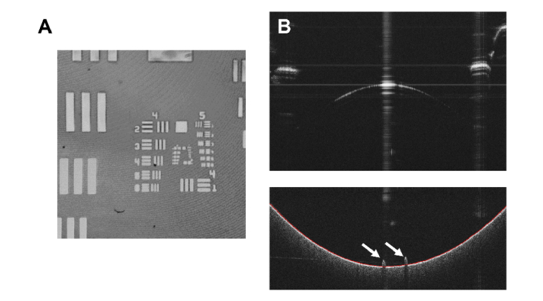
As described in section 2.2.2, we calibrated the location of the anterior segment imaging plane using a USAF 1951 test target. While not done before every imaging session, this was done anytime the path length of the reference arm was changed. Because the sample arm was designed to internally account for posterior segment path length, this was not a common practice but was occasionally necessary to account for subject ergonomics. Figure 8(A) shows a summed volume projection (SVP) from a calibration volume with the test target located at the anterior segment image plane.
Fig. 8.
Whole eye OCT image plane calibration. A) USAF 1951 test chart at anterior chamber image plane with a field-of-view smaller than other volume acquisitions to better visualize Groups 4 and 5. B) Averaged radial scan of phantom eye for axial length calibration. Anterior surface of the phantom is at the top of the image with saturation artifacts present due to lens apex and lens tube surfaces. Retinal phantom surface with alignment targets (white arrow) and surface segmentation is at the bottom of the image.
Figure 8(B) shows a whole eye OCT averaged radial scan of the axial length phantom. The top portion of Fig. 8(B) contains the anterior region of the eye phantom. The anterior lens-air interface is dim due to the anti-reflective coating on the lens though saturation does still occur at the lens apex. Saturation artifacts are present at the edges of the scan due to reflections from the aluminum lens tubes. At the bottom of the image is the retinal phantom surface which includes three markers for alignment, two of which are shown (white arrows). These markers were used to align the optical axis of the phantom to the optical axis of the whole eye OCT system. Following the methods described in Section 2.2, we measured the curvature of the posterior surface to be 12.9 mm. The designed value for the posterior surface was 13mm. Given a 3D print resolution of 100 µm and mechanical shrinkage during curing of the resin, our result matches well with the nominal value.
3.2 In vivo imaging
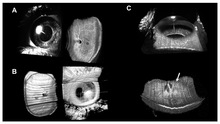
We acquired whole OCT rectangular volumes on all imaged subjects. Selected volumes are shown in Fig. 9 using both ANSI standards. Each volume included simultaneously imaged anterior chamber and retina from the macula to the arcades. Following processing described in Section 2.1, the volumes were rendered individually and placed into their anatomically correct orientation with anterior chamber in front of the retina. On all volumes, saturation artifacts from the corneal apex are present. In these volumetric renderings, the subject’s fovea typically can be seen as a gray disk in the center of the retinal volume with the optic nerve present between the fovea and the nasal edge of the scan. It should also be noted that in Fig. 9(A) the fast scan direction of the volume was taken in the superior-inferior direction versus the more conventional temporal-nasal direction shown in the other two volumes.
Fig. 9.
Whole eye OCT volumetric renderings. A) Right eye of young normal subject with full view of anterior chamber and view of retina from macula to arcades. Acquired with ANSI Z136.1-2014. B) Left eye of normal subject acquired with ANSI Z80.36-2016. Saccade during acquisition was present in both volumes, however, because of the scanning optics, the loss of information appears in the inferior region of the retina and the superior region of the anterior chamber. C) Left eye of papilledema subject with elevated nerve head present (white arrow) acquired with ANSI Z80.36-2016.
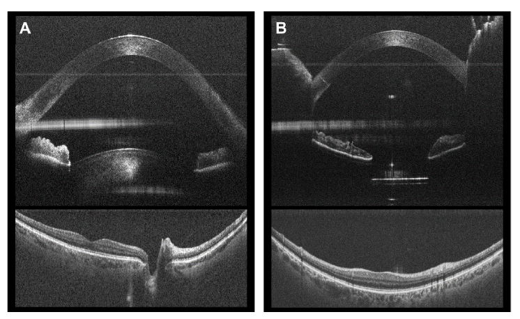
In addition to rectangular volumes, we acquired either repeated radial scans, repeated B-scans at a single location, or both, time permitting. Artifacts due to specular reflection at the corneal apex were present in both. These artifacts were due to saturation of the detector resulting in a clipped, square-like periodic function which contributes additional signal to all frequencies and therefore depths. In Fig. 10, a large reflection artifact is present in the anterior chamber portion of the image and was due to the exit surface of the first cube beamsplitter (Fig. 2(A), 6(A)) which was co-located with the 2nd order coherence revival peak.
Fig. 10.
Whole eye OCT registered and averaged B-scans. Anterior chamber and retinal regions of the B-scans processed separately, cropped, and reoriented in an anatomically correct orientation A) Normal subject with anterior crystalline lens shown. Taken from temporal-nasal radial from averaged radial volume. B) Pseudophakic subject with intraocular lens seen below the iris and eye lids surrounding cornea. Taken from inferior-superior radial from averaged radial volume.
For quantitative measurements, we utilized the 100 kHz laser and repeated radial scan pattern for improved tissue contrast. The reflection artifact from the beamsplitter, while not desired, was located within the image such that it did not interfere with locating critical tissue surfaces. Twelve eyes from six subjects were imaged with both OCT and MRI for a pilot comparison to measure Rc. An example left eye from one of the subject’s in this pilot population can be seen in Fig. 11.
Fig. 11.
Left eye of subject with cataract with representative whole eye OCT (ANSI Z80.36-2016) and MRI images. Cataract in this eye limited light throughput to retina. However even with this limitation, accurate segmentation of the RPE was possible. A) Acquired retinal whole eye OCT averaged radial scan and segmentation B) Dewarped whole eye OCT averaged radial scan and segmentation with isotropic scaling. Average Rc was measured to be 11.5 mm. C) MRI slice showing left eye with cataract present. Measured Rc was 11.2 mm.
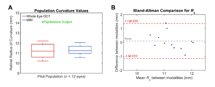
The mean Rc as measured by whole eye OCT was 11.2 ± 0.7 mm, and the mean Rc as measured by MRI was 11.3 mm ± 0.5 mm. There was not a statistically significant difference between the two modalities in measuring retinal curvature in this small population (p = 0.910). The mean ocular axial length measured with OCT was 23.86 ± 0.57mm. Figure 12 shows the population distribution with whole eye OCT measurements in red and MRI measurements in blue which were comparable to previously published values on eye shape in healthy subjects [47].
Fig. 12.
A) Boxplot of pilot study comparing measured retinal curvature with whole eye OCT (red) and MRI (blue). A single papilledema subject (shown in green) was measured with whole eye OCT and was flatter than our normal population by more than four standard deviations. B) Bland-Altman comparison of curvature between MRI and OCT.
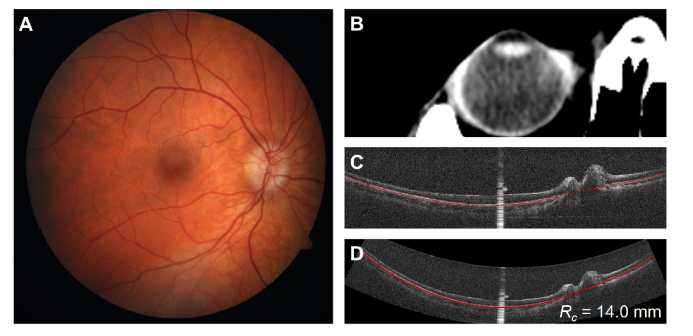
Additionally, we imaged a subject with papilledema with whole eye OCT (Fig. 13). While no comparison was done to a reference modality, their measured Rc was flatter than our normal population mean by more than two standard deviations (green, Fig. 12). This is consistent with previously described posterior eye flattening associated with increased ICP seen in MRI [52] and offers a potential area of study.
Fig. 13.
Right eye of subject with papilledema and elevated intracranial pressure A) Fundus photograph with characteristic blurring of optic disc margins indicative of optic nerve head edema B) CT image cropped to show the right eye of the subject. C) Acquired retinal whole eye OCT (ANSI Z80.36-2016) averaged radial scan and segmentation. The bright, vertical central saturation artifact is from corneal reflection. D) De-warped OCT image and segmentation with isotropic scaling. Measured Rc is 14.0 mm which is flatter than normal and consistent with increased intracranial pressure.
4. Discussion
While there have been previously developed OCT systems capable of imaging the anterior and posterior regions of the human eye [25,28–35], none thus far can simultaneously image both the anterior chamber and the retina with large fields of view using a single source and single detector. Previous systems were capable of imaging the entire anterior chamber or anterior segment but have been limited in their ability to image the retina. Single source systems that image both regions simultaneously have achieved only ~18° FOV [33–35] on the retina with some limited to only ~1° [25]. Systems that switch between imaging planes (thus increasing acquisition time) have been limited to 25° FOV or less [31,32]. In contrast, the system presented here images the retina with a 55° FOV and is comparable to current generation clinical imaging systems that are dedicated to imaging only the retina. Simultaneously acquiring the anterior and posterior regions of the eye allows correction of optical distortions present within the posterior imaging plane using only one set of data [18] with retinal curvature being only one potential morphometric measurement.
Creating a system that images both regions simultaneously comes with trade-offs, however. To maximize the area in which we could measure retinal curvature, during our design we optimized for retinal field-of-view. However, to accommodate the physical presence of the cube beamsplitters in the imaging optics (required for imaging the anterior chamber), 55° retinal FOV became our upper limit which is significantly smaller than the ultra-wide FOV retinal-only OCT systems that achieve between 80 and 100° FOV [53,54]. The last of the cube beamsplitters utilized a wire grid polarizer and introduced an additional compromise. An advantage of these splitters is their wide acceptance angle for a broad wavelength range over the conventional dielectric cube splitters used elsewhere in the system, ± 30° versus ± 2.5°. However, one significant drawback is that their reflection efficiency is only 80% compared to greater than 99% for the dielectric cubes, and thus we limited its use to only where we needed large angles of incidence.
We utilized linear polarization multiplexing to generate two distinct optical paths in the sample arm and the coherence revival effect present within both lasers to frequency multiplex both imaging planes into a single OCT scan. However, it should be noted that these techniques are not dependent on one another. With changes to either the sample arm path lengths or the addition of a second reference arm, one could use a laser with a narrower instantaneous line width [25] and the polarization multiplexing topology described in Section 2.1 to achieve similar results. It should be noted that because the anterior chamber and retinal imaging planes and corresponding imaging paths were polarization multiplexed, this allowed us to independently control their respective path lengths. Following initial alignment and calibration the reference arm and anterior chamber imaging path remained static but the retinal arm Diopter control optics of the sample arm were located on a highly repeatable, linear, motorized stage. This allowed us to account for subjects with different ocular lengths without the need of adjusting the reference arm or recalibrating the system between imaging sessions.
While polarization was used to create two imaging planes, this topology was not suitable for conventional polarization sensitive OCT (PS-OCT) [55]. Here each tissue image plane was interrogated with only a single linear polarization, S-polarization for the anterior chamber and P-polarization for the posterior segment, providing only partially the information needed to compute the Jones matrix [55]. Additionally, this system utilized only a single detector and not a polarization diversity detection scheme [56–58]; however, there may be some benefit to doing so. Each polarization multiplexed channel would have its own detector allowing for more reference power being utilized without saturating the detector, and any frequency information overlap between the two polarization states would be better separated.
Imaging both the anterior chamber and posterior segment simultaneously offers a wealth of information, however, generating individual ocular optical models required several assumptions. One limitation of the system was that it primarily imaged the anterior chamber and not the entire anterior segment including the full crystalline lens. Figure 10(B) does show an acrylic intraocular lens present within the image but this was an exception rather than the rule. While having the entire lens would be undoubtedly beneficial, differences in modeled optical distortion due to the lens between individuals is minimal due to the retinal imaging beam pivoting through, instead of across, the lens. This allows the individual beam to be focused onto the retina and have little angular change to the beam’s chief ray. An exception to this is comparing phakic and pseudophakic eyes, and for pseudophakic eyes, our optical model included an acrylic intraocular lens in place of the gradient index lens of the Polans eye model [38].
It should be noted that current clinical biometers utilize a single averaged group index to estimate eye length [59,60]. In our model we included individualized optical parameters such as corneal curvature, thickness, a modeled lens, and group indices of the cornea, lens, and aqueous/vitreous [43,44]. Because the optical properties of the crystalline lens index and shape remain active areas of research [61–64] and due to individual and age dependent gradient refractive index and dynamic shape changes in non-mydriatic eyes, this may be a source of variability in the measurements that would affect any system imaging through the lens.
The important parameters that affected retinal shape are ocular axial length and system-to-eye distance. Our group as well as others have previously shown that adjusting the position between the subject and system results in a variation of retinal shape [18,53,65]. Estimating subject distance along the optical axis with our whole eye system was relatively straight forward. We compared the distance between the calibration depth of the anterior chamber imaging path to the depth of the corneal apex within a given volume. These distances were entirely in air and a group index of refraction was assumed to be ng-air = 1 allowing the optical path length difference between the two measurements to directly measure the physical length. Lateral shift or rotation away from the optical axis can also cause changes in the retinal field-of-view. This was mitigated by having the subject fixate on the integrated target and aligning the system such that the corneal saturation artifact was centered. Lack of compliance by the subject or misalignment by the system operator would introduce error to the optical model. This error could be further reduced in the future through automated pupil tracking [65].
MRI is currently the standard used to measure posterior eye shape [12,13,49,66] but is limited by cost, resolution, and accessibility. In the small pilot study shown in Section 3.2, retinal curvature as measured only with whole eye OCT based parameters was found to not be statistically significantly different from MRI; a larger, powered study is needed to definitely demonstrate the biometric equivalence of the two platforms. If the measurements are shown to be equivalent, this could open areas for research in subjects with high myopia [12,13,66] or subjects with elevated intracranial pressure where the posterior eye is being pushed in toward the vitreous [52]. In addition to these potential applications for retinal shape and because the system images the entire anterior chamber as well as the retina, whole eye OCT offers the potential for other metrics which could entirely be captured within a single volume as well. Other metrics from a single whole eye volume could include corneal shape and thickness [7,9], anterior chamber angle and depth [67], and ocular axial length [27,28,32,35] some of which we performed as part of the optical distortion correction shown in Section 2.2.
5. Conclusion
We have developed and demonstrated a high speed OCT system capable of truly simultaneous imaging of both the anterior and posterior eye with sufficient field of view to visualize the full anterior chamber width, macula, optic nerve, and retina to the arcades within a single acquisition. This has important implications both for clinical and research ocular imaging as well as for ocular biometric applications.
Acknowledgments
We would like to thank Landon C. Meekins, MD and Sidney M. Gospe III, MD, PhD (Department of Ophthalmology, Duke University Medical Center) for their help and conversations regarding neuro-ophthalmology patient imaging.
We would like to thank Alice Liu (Department of Ophthalmology, Duke University Medical Center) for her assistance with OCT image segmentation.
Funding
We acknowledge support from the National Institutes of Health (R01-EY024312).
Disclosures
RPM: None, JP: None, BK: None, MJA: None, CLJ: None, RRV: None, JAI: Leica Microsystems, (P,R), Carl Zeiss Meditec (P,R), ANK: None
References
- 1.Huang D., Swanson E. A., Lin C. P., Schuman J. S., Stinson W. G., Chang W., Hee M. R., Flotte T., Gregory K., Puliafito C. A., Fujimoto J. G., “Optical coherence tomography,” Science 254(5035), 1178–1181 (1991). 10.1126/science.1957169 [DOI] [PMC free article] [PubMed] [Google Scholar]
- 2.Swanson E. A., Izatt J. A., Hee M. R., Huang D., Lin C. P., Schuman J. S., Puliafito C. A., Fujimoto J. G., “In vivo retinal imaging by optical coherence tomography,” Opt. Lett. 18(21), 1864–1866 (1993). 10.1364/OL.18.001864 [DOI] [PubMed] [Google Scholar]
- 3.Izatt J. A., Hee M. R., Swanson E. A., Lin C. P., Huang D., Schuman J. S., Puliafito C. A., Fujimoto J. G., “Micrometer-scale resolution imaging of the anterior eye in vivo with optical coherence tomography,” Arch. Ophthalmol. 112(12), 1584–1589 (1994). 10.1001/archopht.1994.01090240090031 [DOI] [PubMed] [Google Scholar]
- 4.Drexler W., Morgner U., Ghanta R. K., Kärtner F. X., Schuman J. S., Fujimoto J. G., “Ultrahigh-resolution ophthalmic optical coherence tomography,” Nat. Med. 7(4), 502–507 (2001). 10.1038/86589 [DOI] [PMC free article] [PubMed] [Google Scholar]
- 5.Yasuno Y., Madjarova V. D., Makita S., Akiba M., Morosawa A., Chong C., Sakai T., Chan K.-P., Itoh M., Yatagai T., “Three-dimensional and high-speed swept-source optical coherence tomography for in vivo investigation of human anterior eye segments,” Opt. Express 13(26), 10652–10664 (2005). 10.1364/OPEX.13.010652 [DOI] [PubMed] [Google Scholar]
- 6.Koozekanani D., Boyer K., Roberts C., “Retinal thickness measurements from optical coherence tomography using a Markov boundary model,” IEEE Trans. Med. Imaging 20(9), 900–916 (2001). 10.1109/42.952728 [DOI] [PubMed] [Google Scholar]
- 7.Fukuda S., Kawana K., Yasuno Y., Oshika T., “Anterior ocular biometry using 3-dimensional optical coherence tomography,” Ophthalmology 116(5), 882–889 (2009). 10.1016/j.ophtha.2008.12.022 [DOI] [PubMed] [Google Scholar]
- 8.Tang M., Chen A., Li Y., Huang D., “Corneal power measurement with Fourier-domain optical coherence tomography,” J. Cataract Refract. Surg. 36(12), 2115–2122 (2010). 10.1016/j.jcrs.2010.07.018 [DOI] [PMC free article] [PubMed] [Google Scholar]
- 9.McNabb R. P., Farsiu S., Stinnett S. S., Izatt J. A., Kuo A. N., “Optical coherence tomography accurately measures corneal power change from laser refractive surgery,” Ophthalmology 122(4), 677–686 (2015). 10.1016/j.ophtha.2014.10.003 [DOI] [PMC free article] [PubMed] [Google Scholar]
- 10.Lee A. C., Qazi M. A., Pepose J. S., “Biometry and intraocular lens power calculation,” Curr. Opin. Ophthalmol. 19(1), 13–17 (2008). 10.1097/ICU.0b013e3282f1c5ad [DOI] [PubMed] [Google Scholar]
- 11.Hitzenberger C. K., Drexler W., Leitgeb R. A., Findl O., Fercher A. F., “Key Developments for Partial Coherence Biometry and Optical Coherence Tomography in the Human Eye Made in Vienna,” Invest. Ophthalmol. Vis. Sci. 57(9), OCT460 (2016). 10.1167/iovs.16-19362 [DOI] [PubMed] [Google Scholar]
- 12.Moriyama M., Ohno-Matsui K., Hayashi K., Shimada N., Yoshida T., Tokoro T., Morita I., “Topographic analyses of shape of eyes with pathologic myopia by high-resolution three-dimensional magnetic resonance imaging,” Ophthalmology 118(8), 1626–1637 (2011). 10.1016/j.ophtha.2011.01.018 [DOI] [PubMed] [Google Scholar]
- 13.Ohno-Matsui K., “Proposed classification of posterior staphylomas based on analyses of eye shape by three-dimensional magnetic resonance imaging and wide-field fundus imaging,” Ophthalmology 121(9), 1798–1809 (2014). 10.1016/j.ophtha.2014.03.035 [DOI] [PubMed] [Google Scholar]
- 14.Shinohara K., Moriyama M., Shimada N., Nagaoka N., Ishibashi T., Tokoro T., Ohno-Matsui K., “Analyses of shape of eyes and structure of optic nerves in eyes with tilted disc syndrome by swept-source optical coherence tomography and three-dimensional magnetic resonance imaging,” Eye (Lond.) 27(11), 1233–1241 (2013). 10.1038/eye.2013.202 [DOI] [PMC free article] [PubMed] [Google Scholar]
- 15.Ohno-Matsui K., Akiba M., Modegi T., Tomita M., Ishibashi T., Tokoro T., Moriyama M., “Association between shape of sclera and myopic retinochoroidal lesions in patients with pathologic myopia,” Invest. Ophthalmol. Vis. Sci. 53(10), 6046–6061 (2012). 10.1167/iovs.12-10161 [DOI] [PubMed] [Google Scholar]
- 16.Podoleanu A., Charalambous I., Plesea L., Dogariu A., Rosen R., “Correction of distortions in optical coherence tomography imaging of the eye,” Phys. Med. Biol. 49(7), 1277–1294 (2004). 10.1088/0031-9155/49/7/015 [DOI] [PubMed] [Google Scholar]
- 17.Zawadzki R. J., Fuller A. R., Choi S. S., Wiley D. F., Hamann B., Werner J. S., “Correction of motion artifacts and scanning beam distortions in 3D ophthalmic optical coherence tomography imaging,” in SPIE BiOS, (SPIE, 2007), 11. [Google Scholar]
- 18.Kuo A. N., McNabb R. P., Chiu S. J., El-Dairi M. A., Farsiu S., Toth C. A., Izatt J. A., “Correction of ocular shape in retinal optical coherence tomography and effect on current clinical measures,” Am. J. Ophthalmol. 156(2), 304–311 (2013). 10.1016/j.ajo.2013.03.012 [DOI] [PMC free article] [PubMed] [Google Scholar]
- 19.Wieser W., Klein T., Neubauer A., Reznicek L., Kampik A., Huber R., “Feasability of ultrawide-field retinal-shape measurement with MHz-OCT,” Invest. Ophthalmol. Vis. Sci. 54, 1469 (2013).23361509 [Google Scholar]
- 20.Malkin A. G., Goldstein J. E., Massof R. W., “Interpretation of health and vision utilities in low vision patients,” Optom. Vis. Sci. 89(3), 288–295 (2012). 10.1097/OPX.0b013e318241720f [DOI] [PubMed] [Google Scholar]
- 21.Chou T.-H., Kocaoglu O. P., Borja D., Ruggeri M., Uhlhorn S. R., Manns F., Porciatti V., “Postnatal elongation of eye size in DBA/2J mice compared with C57BL/6J mice: in vivo analysis with whole-eye OCT,” Invest. Ophthalmol. Vis. Sci. 52(6), 3604–3612 (2011). 10.1167/iovs.10-6340 [DOI] [PMC free article] [PubMed] [Google Scholar]
- 22.Leitgeb R., Hitzenberger C., Fercher A., “Performance of fourier domain vs. time domain optical coherence tomography,” Opt. Express 11(8), 889–894 (2003). 10.1364/OE.11.000889 [DOI] [PubMed] [Google Scholar]
- 23.Choma M., Sarunic M., Yang C., Izatt J., “Sensitivity advantage of swept source and Fourier domain optical coherence tomography,” Opt. Express 11(18), 2183–2189 (2003). 10.1364/OE.11.002183 [DOI] [PubMed] [Google Scholar]
- 24.de Boer J. F., Cense B., Park B. H., Pierce M. C., Tearney G. J., Bouma B. E., “Improved signal-to-noise ratio in spectral-domain compared with time-domain optical coherence tomography,” Opt. Lett. 28(21), 2067–2069 (2003). 10.1364/OL.28.002067 [DOI] [PubMed] [Google Scholar]
- 25.Grulkowski I., Liu J. J., Potsaid B., Jayaraman V., Lu C. D., Jiang J., Cable A. E., Duker J. S., Fujimoto J. G., “Retinal, anterior segment and full eye imaging using ultrahigh speed swept source OCT with vertical-cavity surface emitting lasers,” Biomed. Opt. Express 3(11), 2733–2751 (2012). 10.1364/BOE.3.002733 [DOI] [PMC free article] [PubMed] [Google Scholar]
- 26.Choi W., Potsaid B., Jayaraman V., Baumann B., Grulkowski I., Liu J. J., Lu C. D., Cable A. E., Huang D., Duker J. S., Fujimoto J. G., “Phase-sensitive swept-source optical coherence tomography imaging of the human retina with a vertical cavity surface-emitting laser light source,” Opt. Lett. 38(3), 338–340 (2013). 10.1364/OL.38.000338 [DOI] [PMC free article] [PubMed] [Google Scholar]
- 27.Grulkowski I., Liu J. J., Zhang J. Y., Potsaid B., Jayaraman V., Cable A. E., Duker J. S., Fujimoto J. G., “Reproducibility of a long-range swept-source optical coherence tomography ocular biometry system and comparison with clinical biometers,” Ophthalmology 120(11), 2184–2190 (2013). 10.1016/j.ophtha.2013.04.007 [DOI] [PMC free article] [PubMed] [Google Scholar]
- 28.Ruggeri M., Uhlhorn S. R., De Freitas C., Ho A., Manns F., Parel J.-M., “Imaging and full-length biometry of the eye during accommodation using spectral domain OCT with an optical switch,” Biomed. Opt. Express 3(7), 1506–1520 (2012). 10.1364/BOE.3.001506 [DOI] [PMC free article] [PubMed] [Google Scholar]
- 29.Dai C., Zhou C., Fan S., Chen Z., Chai X., Ren Q., Jiao S., “Optical coherence tomography for whole eye segment imaging,” Opt. Express 20(6), 6109–6115 (2012). 10.1364/OE.20.006109 [DOI] [PubMed] [Google Scholar]
- 30.Fan S., Li L., Li Q., Dai C., Ren Q., Jiao S., Zhou C., “Dual band dual focus optical coherence tomography for imaging the whole eye segment,” Biomed. Opt. Express 6(7), 2481–2493 (2015). 10.1364/BOE.6.002481 [DOI] [PMC free article] [PubMed] [Google Scholar]
- 31.Nankivil D., Waterman G., LaRocca F., Keller B., Kuo A. N., Izatt J. A., “Handheld, rapidly switchable, anterior/posterior segment swept source optical coherence tomography probe,” Biomed. Opt. Express 6(11), 4516–4528 (2015). 10.1364/BOE.6.004516 [DOI] [PMC free article] [PubMed] [Google Scholar]
- 32.Grulkowski I., Manzanera S., Cwiklinski L., Sobczuk F., Karnowski K., Artal P., “Swept source optical coherence tomography and tunable lens technology for comprehensive imaging and biometry of the whole eye,” Optica 5(1), 52–59 (2018). 10.1364/OPTICA.5.000052 [DOI] [Google Scholar]
- 33.Jeong H.-W., Lee S.-W., Kim B.-M., “Spectral-domain OCT with dual illumination and interlaced detection for simultaneous anterior segment and retina imaging,” Opt. Express 20(17), 19148–19159 (2012). 10.1364/OE.20.019148 [DOI] [PubMed] [Google Scholar]
- 34.Dhalla A.-H., Nankivil D., Bustamante T., Kuo A., Izatt J. A., “Simultaneous swept source optical coherence tomography of the anterior segment and retina using coherence revival,” Opt. Lett. 37(11), 1883–1885 (2012). 10.1364/OL.37.001883 [DOI] [PMC free article] [PubMed] [Google Scholar]
- 35.Kim H.-J., Kim M., Hyeon M. G., Choi Y., Kim B.-M., “Full ocular biometry through dual-depth whole-eye optical coherence tomography,” Biomed. Opt. Express 9(2), 360–372 (2018). 10.1364/BOE.9.000360 [DOI] [PMC free article] [PubMed] [Google Scholar]
- 36.Palmer K. F., Williams D., “Optical properties of water in the near infrared*,” J. Opt. Soc. Am. 64(8), 1107–1110 (1974). 10.1364/JOSA.64.001107 [DOI] [Google Scholar]
- 37.Marschall S., Pedersen C., Andersen P. E., “Investigation of the impact of water absorption on retinal OCT imaging in the 1060 nm range,” Biomed. Opt. Express 3(7), 1620–1631 (2012). 10.1364/BOE.3.001620 [DOI] [PMC free article] [PubMed] [Google Scholar]
- 38.Polans J., Jaeken B., McNabb R. P., Artal P., Izatt J. A., “Wide-field optical model of the human eye with asymmetrically tilted and decentered lens that reproduces measured ocular aberrations,” Optica 2(2), 124–134 (2015). 10.1364/OPTICA.2.000124 [DOI] [Google Scholar]
- 39.Polans J., Jaeken B., McNabb R. P., Artal P., Izatt J. A., “Asymmetric wide-field optical model of the human eye with tilted and decentered crystalline lens that reproduces experimentally measured aberrations: errata,” Optica 5(11), 1461 (2018). 10.1364/OPTICA.5.001461 [DOI] [Google Scholar]
- 40.So-Young B., Osung K., Yoon-Ho K., “High-resolution mode-spacing measurement of the blue-violet diode laser using interference of felds created with time delays greater than the coherence time,” Jpn. J. Appl. Phys. 46(12), 7720–7723 (2007). 10.1143/JJAP.46.7720 [DOI] [Google Scholar]
- 41.Dhalla A.-H., Nankivil D., Izatt J. A., “Complex conjugate resolved heterodyne swept source optical coherence tomography using coherence revival,” Biomed. Opt. Express 3(3), 633–649 (2012). 10.1364/BOE.3.000633 [DOI] [PMC free article] [PubMed] [Google Scholar]
- 42.Chiu S. J., Li X. T., Nicholas P., Toth C. A., Izatt J. A., Farsiu S., “Automatic segmentation of seven retinal layers in SDOCT images congruent with expert manual segmentation,” Opt. Express 18(18), 19413–19428 (2010). 10.1364/OE.18.019413 [DOI] [PMC free article] [PubMed] [Google Scholar]
- 43.Lin R. C., Shure M. A., Rollins A. M., Izatt J. A., Huang D., “Group index of the human cornea at 1.3-microm wavelength obtained in vitro by optical coherence domain reflectometry,” Opt. Lett. 29(1), 83–85 (2004). 10.1364/OL.29.000083 [DOI] [PubMed] [Google Scholar]
- 44.Kuo A. N., McNabb R. P., Zhao M., Larocca F., Stinnett S. S., Farsiu S., Izatt J. A., “Corneal biometry from volumetric SDOCT and comparison with existing clinical modalities,” Biomed. Opt. Express 3(6), 1279–1290 (2012). 10.1364/BOE.3.001279 [DOI] [PMC free article] [PubMed] [Google Scholar]
- 45.Westphal V., Rollins A., Radhakrishnan S., Izatt J., “Correction of geometric and refractive image distortions in optical coherence tomography applying Fermat’s principle,” Opt. Express 10(9), 397–404 (2002). 10.1364/OE.10.000397 [DOI] [PubMed] [Google Scholar]
- 46.Zhao M., Kuo A. N., Izatt J. A., “3D refraction correction and extraction of clinical parameters from spectral domain optical coherence tomography of the cornea,” Opt. Express 18(9), 8923–8936 (2010). 10.1364/OE.18.008923 [DOI] [PubMed] [Google Scholar]
- 47.Atchison D. A., Smith G., Optics of the Human Eye (Butterworth-Heinemann, 2000). [Google Scholar]
- 48.Ortiz S., Siedlecki D., Grulkowski I., Remon L., Pascual D., Wojtkowski M., Marcos S., “Optical distortion correction in optical coherence tomography for quantitative ocular anterior segment by three-dimensional imaging,” Opt. Express 18(3), 2782–2796 (2010). 10.1364/OE.18.002782 [DOI] [PubMed] [Google Scholar]
- 49.Kuo A. N., Verkicharla P. K., McNabb R. P., Cheung C. Y., Hilal S., Farsiu S., Chen C., Wong T. Y., Ikram M. K., Cheng C. Y., Young T. L., Saw S. M., Izatt J. A., “Posterior Eye Shape Measurement With Retinal OCT Compared to MRIPosterior Eye Shape Measurement With Retinal OCT,” Invest. Ophthalmol. Vis. Sci. 57, 196 (2016). 10.1167/iovs.15-18886 [DOI] [PMC free article] [PubMed] [Google Scholar]
- 50.Verkicharla P. K., Suheimat M., Pope J. M., Sepehrband F., Mathur A., Schmid K. L., Atchison D. A., “Validation of a partial coherence interferometry method for estimating retinal shape,” Biomed. Opt. Express 6(9), 3235–3247 (2015). 10.1364/BOE.6.003235 [DOI] [PMC free article] [PubMed] [Google Scholar]
- 51.Atchison D. A., Pritchard N., Schmid K. L., Scott D. H., Jones C. E., Pope J. M., “Shape of the retinal surface in emmetropia and myopia,” Invest. Ophthalmol. Vis. Sci. 46(8), 2698–2707 (2005). 10.1167/iovs.04-1506 [DOI] [PubMed] [Google Scholar]
- 52.Brodsky M. C., Vaphiades M., “Magnetic resonance imaging in pseudotumor cerebri,” Ophthalmology 105(9), 1686–1693 (1998). 10.1016/S0161-6420(98)99039-X [DOI] [PubMed] [Google Scholar]
- 53.Kolb J. P., Klein T., Kufner C. L., Wieser W., Neubauer A. S., Huber R., “Ultra-widefield retinal MHz-OCT imaging with up to 100 degrees viewing angle,” Biomed. Opt. Express 6(5), 1534–1552 (2015). 10.1364/BOE.6.001534 [DOI] [PMC free article] [PubMed] [Google Scholar]
- 54.McNabb R. P., Grewal D. S., Mehta R., Schuman S. G., Izatt J. A., Mahmoud T. H., Jaffe G. J., Mruthyunjaya P., Kuo A. N., “Wide field of view swept-source optical coherence tomography for peripheral retinal disease,” Br. J. Ophthalmol. 100(10), 1377–1382 (2016). 10.1136/bjophthalmol-2015-307480 [DOI] [PMC free article] [PubMed] [Google Scholar]
- 55.de Boer J. F., Hitzenberger C. K., Yasuno Y., “Polarization sensitive optical coherence tomography - a review [Invited],” Biomed. Opt. Express 8(3), 1838–1873 (2017). 10.1364/BOE.8.001838 [DOI] [PMC free article] [PubMed] [Google Scholar]
- 56.Saxer C. E., de Boer J. F., Park B. H., Zhao Y., Chen Z., Nelson J. S., “High-speed fiber based polarization-sensitive optical coherence tomography of in vivo human skin,” Opt. Lett. 25(18), 1355–1357 (2000). 10.1364/OL.25.001355 [DOI] [PubMed] [Google Scholar]
- 57.Götzinger E., Baumann B., Pircher M., Hitzenberger C. K., “Polarization maintaining fiber based ultra-high resolution spectral domain polarization sensitive optical coherence tomography,” Opt. Express 17(25), 22704–22717 (2009). 10.1364/OE.17.022704 [DOI] [PMC free article] [PubMed] [Google Scholar]
- 58.Braaf B., Vermeer K. A., de Groot M., Vienola K. V., de Boer J. F., “Fiber-based polarization-sensitive OCT of the human retina with correction of system polarization distortions,” Biomed. Opt. Express 5(8), 2736–2758 (2014). 10.1364/BOE.5.002736 [DOI] [PMC free article] [PubMed] [Google Scholar]
- 59.Haigis W., Lege B., Miller N., Schneider B., “Comparison of immersion ultrasound biometry and partial coherence interferometry for intraocular lens calculation according to Haigis,” Graefes Arch. Clin. Exp. Ophthalmol. 238(9), 765–773 (2000). 10.1007/s004170000188 [DOI] [PubMed] [Google Scholar]
- 60.Wang L., Shirayama M., Ma X. J., Kohnen T., Koch D. D., “Optimizing intraocular lens power calculations in eyes with axial lengths above 25.0 mm,” J. Cataract Refract. Surg. 37(11), 2018–2027 (2011). 10.1016/j.jcrs.2011.05.042 [DOI] [PubMed] [Google Scholar]
- 61.de Castro A., Ortiz S., Gambra E., Siedlecki D., Marcos S., “Three-dimensional reconstruction of the crystalline lens gradient index distribution from OCT imaging,” Opt. Express 18(21), 21905–21917 (2010). 10.1364/OE.18.021905 [DOI] [PubMed] [Google Scholar]
- 62.Pérez-Merino P., Velasco-Ocana M., Martinez-Enriquez E., Marcos S., “OCT-based crystalline lens topography in accommodating eyes,” Biomed. Opt. Express 6(12), 5039–5054 (2015). 10.1364/BOE.6.005039 [DOI] [PMC free article] [PubMed] [Google Scholar]
- 63.Martinez-Enriquez E., Pérez-Merino P., Velasco-Ocana M., Marcos S., “OCT-based full crystalline lens shape change during accommodation in vivo,” Biomed. Opt. Express 8(2), 918–933 (2017). 10.1364/BOE.8.000918 [DOI] [PMC free article] [PubMed] [Google Scholar]
- 64.Ruggeri M., Williams S., Heilman B. M., Yao Y., Chang Y.-C., Mohamed A., Sravani N. G., Durkee H., Rowaan C., Gonzalez A., Ho A., Parel J.-M., Manns F., “System for on- and off-axis volumetric OCT imaging and ray tracing aberrometry of the crystalline lens,” Biomed. Opt. Express 9(8), 3834–3851 (2018). 10.1364/BOE.9.003834 [DOI] [PMC free article] [PubMed] [Google Scholar]
- 65.Carrasco-Zevallos O., Nankivil D., Keller B., Viehland C., Lujan B. J., Izatt J. A., “Pupil tracking optical coherence tomography for precise control of pupil entry position,” Biomed. Opt. Express 6(9), 3405–3419 (2015). 10.1364/BOE.6.003405 [DOI] [PMC free article] [PubMed] [Google Scholar]
- 66.Pope J. M., Verkicharla P. K., Sepehrband F., Suheimat M., Schmid K. L., Atchison D. A., “Three-dimensional MRI study of the relationship between eye dimensions, retinal shape and myopia,” Biomed. Opt. Express 8(5), 2386–2395 (2017). 10.1364/BOE.8.002386 [DOI] [PMC free article] [PubMed] [Google Scholar]
- 67.Radhakrishnan S., See J., Smith S. D., Nolan W. P., Ce Z., Friedman D. S., Huang D., Li Y., Aung T., Chew P. T. K., “Reproducibility of anterior chamber angle measurements obtained with anterior segment optical coherence tomography,” Invest. Ophthalmol. Vis. Sci. 48(8), 3683–3688 (2007). 10.1167/iovs.06-1120 [DOI] [PubMed] [Google Scholar]


