Abstract
Background:
This experimental study assessed reverse torque of indexed and nonindexed (NI) abutments in Morse Taper (MT) implants in a mechanical fatigue test.
Materials and Methods:
In this experimental study It was used 37 implants MT and over them installed Pilar Flex abutments (4.8 mm × 6 mm × 1.5 mm). The groups were as follows: Group A used 19 MT implants with a NI Pilar Flex abutment loaded with 32 N/cm and Group B used 18 MT implants with an indexed (IN) Pilar Flex abutment loaded with 20 N/cm. The abutments were tested according to ISO standard 14801/2007. The specimens were installed at 30° from the axial axis and underwent a 133 N load, 4 Hz frequency, and 1,000,000 cycles. Once the test was completed, the reverse torque was provided by an electronic torque meter. Data were submitted to statistical analysis using the t-test for independent samples and paired t-test. The significance level was considered P < 0.05.
Results:
Results obtained showed that the indexed Pilar Flex abutment had a percentage of torque loss from the initial torque of 49% and the NI Pilar Flex abutment lost 14%. Paired Student's t-tests revealed that for both NI (P < 0.001) and indexed (P < 0.001) abutments, the counter torque values were significantly lower than those applied at the initial torque.
Conclusion:
According on the methodology used, the NI Pilar Flex abutment was more effective regarding the reverse torque in single-unit implant prostheses versus the indexed Pilar Flex abutment. A greater loosening in the indexed Pilar Flex abutment retaining screw was noted in the reverse torque test, and the Pilar Flex abutment failed to show good outcomes related to the cold welding effect.
Key Words: Dental implant–abutment design, dental implants, torque
INTRODUCTION
Implant dentistry is a constantly evolving specialty, where antirotational systems for prosthesis–implant connections have been frequently modified in pursuit of a better adaptation with fewer risks of fracture and abutment retaining screw loosening.[1,2]
External hexagon (EH) was the first antirotational system in implant dentistry.[3,4,5] Years later, to improve stability results in implant prostheses, internal hexagon (IH) implants were developed.[4,6]
During this evolutionary process, Morse Taper (MT) implants appeared with the advantage of interlocking the abutment and implant walls together. The more the abutment screw is tightened, the more intimate is the contact with the internal implant wall, thus impeding loosening of the abutment.[7,8,9]
These different types of implant–abutment connections can be classified as butt–joint (junction) connections and tapered connections[10] and subclassified according to the presence or absence of an antirotational system, which is commonly achieved through an index in the abutment–implant interface.[11]
Since the nonindexed (NI) MT does not have a smooth internal surface and lacks an installation guide, it is more difficult to maintain the abutment in position.[9] Therefore, the implant with an indexed MT prosthetic connection was developed, where there is an antirotational system that is similar to the IH implant inside the MT implant.[12] This component has a fitted screw, which according to the manufacturers requires a smaller installation torque. This fact has raised concern regarding the abutment's final torque and longevity. Villarinho et al.[9] reported that the presence of the index might negatively affect the biomechanical stability of retaining screws in the tapered abutment.
The occlusal load is another major factor in loosening of the prosthesis retaining screw and fatigue tests are reported by several authors,[8,13] such as a cyclic loading technique, to simulate chewing forces. The fatigue test is accepted as the best way to generate fracture resistance and longevity data for implants and abutments and also to simulate in vivo conditions.[11]
With the concern of offering to our patients' implant prosthesis with greater predictability and longevity, this study has evaluated two prosthetic connection systems of MT implants, the indexed (with fitted screw) and NI abutments undergoing a mechanical cycling fatigue test under dry conditions. The null hypothesis postulated that the types of abutment/connection do not influence reverse torque results following the mechanical cycling fatigue test.
MATERIALS AND METHODS
Samples and preparation of specimens
In this experimental study, 37 implants with prosthetic MT connection (Pross Implantes, Ribeirão Preto, SP, Brazil) made of titanium Grade IV of 3.5 mm diameter and 11.5 mm length, containing the hexagonal indexer inside, were used [Figure 1]. Straight Pilar Flex abutments of 4.8 mm diameter per 6 mm height and 1.5 mm neck height (Pross Implantes, Ribeirão Preto, SP, Brazil) were installed in the implants.
Figure 1.
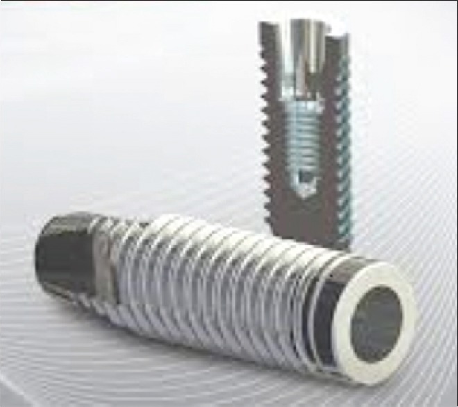
Morse Taper implant with image of the indexer inside the implant. Source: Pross Implantes, 2014, p1.
Pross Implantes has as one of its options for implant-prosthetic rehabilitation, the Pilar Flex abutment, that can be used both for single-unit or multiple implant prostheses. And also, the same abutment can be used for screw and cement-retained implant-supported restorations. The option will depend on case particularities and the technique used by each professional. In this study, a unitary and screwed case was simulated.
In the abutment/implant interface, the screw can be single-body (Pilar Flex NI) which receives tightening larger torque or that abutment may contain a through screw (indexed Pilar Flex) which has a hexagon to fit perfectly into the Cone Morse implant hexagon [Figure 2]. This abutment has a smaller diameter screw that receives a smaller tightening installation torque.
Figure 2.
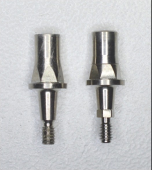
Left: Nonindexed Pilar Flex Morse Taper abutment. Right: Indexed Pilar Flex Morse Taper abutment.
For this reason, two study groups were created; Group A received 18 NI, single-screw Pilar Flex abutments, and a 32 N/cm torque was applied to the implant in each sample. Group B received 19 indexed Pilar Flex abutments with an antirotational system containing the fitted screw, and a 20 N/cm torque was applied, according to the manufacturer's instructions.
The specimens were manufactured using 3/4 inch diameter PVC tubes where the implants were stabilized using a polyurethane resin (Axson Technologies, Saint-Ouen-I'Aumône, France), leaving implant threads exposed about 3 mm above the resin, as per ISO 14801/2007 protocol [Figure 3].[9,14,15,16]
Figure 3.
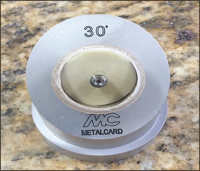
Implant installed in the polyurethane resin and placed on a surface with 30° inclination as per ISO 14801/2007 protocol.
The same operator was calibrated and conducted all tests throughout the study. Samples were tested in a randomized sequence within their groups and then numbered to create a table.[17]
Application and measurement of the installation torque
Using a manual torque meter (Pross Implantes, Ribeirão Preto, SP, Brazil) with a 1.6 mm diameter hexagonal wrench, from the same company, the indexed abutment received 20 N/cm and the NI abutment 32 N/cm according to the manufacturer's instructions. Following 10 min, the torque applied was confirmed.[1,8,13,15,18,19,20]
Manufacture of the protective coping
With the concern of manufacturing highly accurate copings standardized among the 37 specimens, the CAD/CAM system (Amann Girrbach, Vorarlberg, Austria) was used. The Pilar Flex abutment was scanned, and then, a digital drawing of the coping was generated with a 20 mm space between the coping and the abutment, so as to achieve mechanical retention. This coping was produced in order to mimic a crown and protect the head of the Pilar Flex abutment screw so as not to damage it, which would affect insertion of the wrench (1.6 mm diameter) in the reverse torque test.
The copings were cemented onto the abutments with TempBond NE (Kerr, Romulus, Michigan, United States) temporary cement [Figure 4]. Temporary cements were selected in this study to allow access to the abutment screw, following the mechanical cycling test.[12,13]
Figure 4.
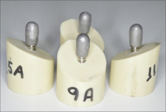
Copings positioned and temporarily cemented onto the Pilar Flex abutment.
Performing the mechanical cycling fatigue test
The specimens were installed on a metallic surface with 30° inclination in the cycling fatigue machine (Erios, São Paulo, SP, Brazil) and received 1,000,000 cycles, with axial loads to the implant/abutment set, simulating a chewing force of 133 N/cm and with 4 Hz frequency, according to the values proposed by ISO standard 14801/2007 [Figure 5].
Figure 5.
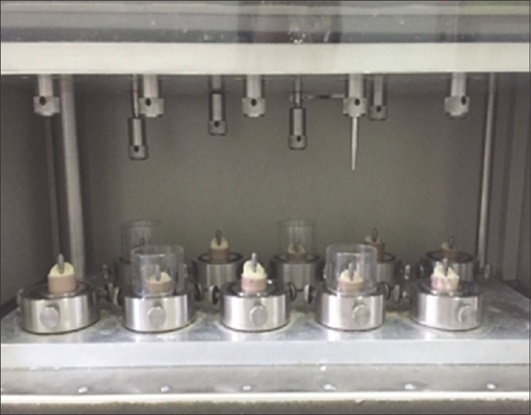
Image of the specimens positioned in the cycling machine.
All tests were conducted at the Material Testing Laboratory of ICT-UNESP, Dentistry School (University of São Paulo) in São José dos Campos, in vitro at a dry place, room temperature (24°C ± 1°C), with 53% ± 1% humidity.[11]
Application and measurement of reverse torque values
Following completion of the cycling test, reverse torque was applied to the 37 Pilar Flex abutment specimens with an electronic torque meter (model TQ 8800, LT Lutron, Taiwan) and the same 1.6 mm diameter hexagonal wrench (Pross Implantes, Ribeirão Preto, SP, Brazil) used for the initial torque.
Individual data were collected and reverse torque values were analyzed. Following the cycling fatigue test, Groups A and B were compared.
Statistical analysis
After the homogeneity of variance was verified through the Levene's test and data, normality distribution was performed using the Shapiro–Wilk test, in order to compare whether there were any differences in the reverse torque values for indexed and NI MT abutments, the Student's t-test was used for independent samples.
To investigate whether there were any differences between the initial torque and reverse torque values for indexed and NI MT abutments, paired Student's t-tests were applied.
Statistical calculations were performed using the SPSS 23 software (SPSS Inc., Chicago, IL, USA), and a significance level of P < 0.05 was adopted.
RESULTS
The Student's t-test for independent samples showed, with 100.0% test power, that the reverse torque values for indexed MT abutments were significantly lower than those obtained with the NI ones (P < 0.001), as shown in Table 1 and Figure 6, i.e., loss of the initial torque in the indexed abutment was on average higher versus the NI abutment.
Table 1.
Mean values and standard deviations of initial and reverse torque in indexed and nonindexed Morse Taper abutments and percentage loss from initial torque (N/cm)
| Morse Taper abutment | Initial torque | Reverse torque | Percentage loss from initial torque (%) |
|---|---|---|---|
| Indexed (n=19) | 20 (0) | 10 (4)B | 49 |
| Nonindexed (n=18) | 32 (0) | 28 (3)A | 14 |
SD in parentheses. Means followed by distinct letters indicate a significant difference in the reverse torque between indexed and nonindexed abutments (P<0.001). SD: Standard deviation
Figure 6.
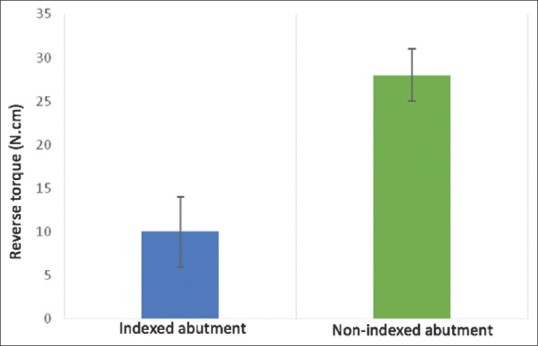
Column diagram of mean reverse torque values in indexed and nonindexed Morse Taper abutments. Key: Vertical bars indicate the standard deviation. Means followed by distinct letters indicate a significant difference in the reverse torque between indexed and nonindexed abutments.
Paired Student's t-tests showed that for both NI (P < 0.001) and indexed abutments (P < 0.001), the reverse torque values were significantly lower than those applied in the initial torque [Table 1]. On average, for NI abutments, there was a 14% torque loss, while for the indexed abutments, the reverse torque was 49% lower than the initial torque.
Another result obtained in this study was that of the 18 NI Pilar Flex abutment specimens, a reverse torque (34 N/cm) greater than the initial torque (32 N/cm) was applied to only two, showing that only 11% of the samples in this group achieved the cold welding effect. For the indexed Pilar Flex abutment, none of the 19 samples obtained a reverse torque greater than the initial torque.
DISCUSSION
In this study, the null hypothesis was rejected since there was a significant difference (P < 0.001) in the reverse torque results for indexed (Group B) and NI abutments (Group A) following the cycling fatigue test.
This study was conducted according to the specifications described by Lee et al.[21] following the fatigue testing protocol for implants, called ISO 14801 Protocol. ISO recommendations were designed for single-unit, endosseous, and transmucosal implants and tested in “worst scenario” applications. Since 2007, ISO guidelines limit tests under wet conditions to 2 Hz and two million cycles. For dry conditions, tests are limited to 15 Hz and up to five million cycles.
Several studies used this protocol;[2,9,22,23] however, rather than a standard, there is a recommendation of parameters made by ISO 14801/2007. Therefore, the present study was performed under dry conditions, with 4 Hz frequency, 30° inclination, 133 N load, and 1 million cycles.
The specimens consisted of single-unit, cemented prostheses with premanufactured titanium grade V abutments. Wiskott et al.[24] noted that premanufactured titanium abutments are 20% more resistant than abutments made of aluminum oxide or zirconium. According to Gehrke et al.[25] the CAD-CAM system allows for better customization and accuracy when manufacturing the abutments. The copings in the present investigation were obtained using CAD-CAM, a methodology that was also used by Yao et al.[19]
Such copings were manufactured to mimic a crown and protect the retaining screw. For cementing, a temporary cement was used to facilitate coping removal and allow access to the screw following the cycling test. This same strategy was recommended in the studies by Ding et al.[12] and Moris et al.[13] However, according to Schittenhelm et al.,[26] the use of provisional cementing as compared to definitive cementing did not interfere in the final investigational result.
Studies[7,27] analyzed NI MT implants and noted loosening of only 0.6% and 0.66% of the abutments, providing high mechanical stability and reduced prosthetic complications, thus being considered reliable for single-tooth rehabilitations in all arches.
The Morse system is defined in regard to the form of adaptation by friction between the metallic surfaces, known as cold welding, characterized by requirement of a reverse torque greater than the insertion torque to release the abutment.[1,6] In the present investigation, the initial torque given in the NI Pilar Flex abutments was 32 N/cm, but after the cycling fatigue test, two of the samples from this group had a removal torque of 34 N/cm. This stability gain did not occur in the IN Pilar Flex, which shows that only 5.4% of all 37 samples (IN + NI group) presented the “cold welding effect. On analysis of results from the NI group only, the cold welding effect was present in 11% of the samples. This finding was shown with greater efficiency in the study by Squier et al.[28] where the mean obtained was 37.16 N/cm reverse torque in 20 samples in ITI synOcta implants with NI abutment, considering an initial torque of 35 N/cm.
The specimens in the present study were manufactured from MT implants of 3.5 mm diameter, abutments of 4.8 mm diameter, 0.6 mm height, and 1.5 mm belt (transmucosal), which endured the entire cycling test with no abutment and/or implant fracture. Different results were found by Quek et al.[29] where EH implants (Nobel Biocare) of various diameters (3.3/3.75/5.0 mm) were used. Of the lower diameter implants, 6/15 showed abutment fracture, while in those of greater diameter, no failures were present following the fatigue test. The authors also suggested that the retaining screw be replaced when it becomes loosened since potential fatigue will result in screw fracture. Nguyen et al.[30] confirmed this finding, showing that lower diameter implants increase the fracture risk, especially in zirconium abutments. In another study, Quek et al.[31] analyzed implants/abutments in three torque settings: as recommended by the manufacturer, −20% and +20% of the recommended torque, and following the cycling test, and they noted that there was no statistical difference when the torque recommended by the manufacturer was used. Under the other conditions, however, there was fracture of the retaining screw, implant, or abutment. Kim et al.[32] used Straumann implants and installed abutments of the same brand and abutments from three different brands, but compatible with this system. Following the cycling fatigue test, more than half of the non-Straumann abutments were fractured, which show that interchanging systems is not recommended. Given these findings, the present study used only abutments made by the implant manufacturer with the recommended torques.
In a fatigue test performed by Ribeiro et al.[33] using 1 million cycles in EH, IH, and MT implants, a better efficiency was noted in the implant–abutment interface of the EH system. Worse results were noted for IH and MT systems due to a lack of accuracy of those components. Similar results were found by Shin et al.,[18] where in a comparison between EH, 8° MT, and 11° MT implants, the best reverse torque result was obtained in EH implants.
Using a methodology similar to that in the study by Villarinho et al.,[9] we were able to note similar results of loss of reverse torque values. In the MT implant with indexed abutment, the authors found a 52.65% loss in reverse torque values, and in the NI abutment, this loss was 13.84%. However, in the present investigation, results were 49% for the indexed abutment and 14% for the NI abutment. Considering the higher loss of reverse torque values for indexed abutments, this suggests greater fragility in this type of abutment and its use can be considered to be vulnerable for single-unit implant prostheses.
The reverse torque values for indexed MT abutments were significantly lower than those obtained with the NI ones (P < 0.001). In this study, different initial torque values were applied because when using a component with a through screw (indexed abutment), a lower initial tightening torque is required, as recommended by the manufacturer.
Loss of the initial torque in the indexed abutment was on average higher versus the NI abutment, thus showing greater loosening of this abutment as compared to the NI one.
Yao et al.[19] evaluated MT implants with indexed and NI abutments and noted a higher fracture rate for indexed abutments. The authors related the findings to the area of greater strain located at the index. In the present study, no fractures or abutment loosening was noted. However, Farina et al.[34] emphasized the importance of frequently repeating the torque for screws of implant prostheses since the authors found a 20%–50% loss of the initial torque following a 1-year simulation of chewing.
New studies will be required in the search for a better understanding of the difference in reverse torque between indexed and NI abutments. The present study suggests that the lower initial torque applied to the indexed abutment may be responsible for such difference. Another possible explanation could be in the accuracy of the fit between implant/indexed abutment interfaces, as already described by Vigolo et al.,[35] Semper et al.,[36] and Semper-Hogg et al.[37] A study comparing indexed and NI MT abutments in fixed prosthesis settings is also warranted.
CONCLUSION
Based on the methodology used and results obtained:
There are significant differences in the reverse torque between indexed and NI abutments, showing greater loosening of the retaining screw in the indexed Pilar Flex abutment
The NI Pilar Flex abutment was more effective regarding the reverse torque in single-unit implant prostheses versus the indexed Pilar Flex abutment
IN and NI Pilar Flex abutments failed to show good outcomes related to the cold welding effect.
Financial support and sponsorship
Nil.
Conflicts of interest
The authors of this manuscript declare that they have no conflicts of interest, real or perceived, financial or nonfinancial in this article.
REFERENCES
- 1.Cerutti-Kopplin D, Rodrigues Neto DJ, Lins do Valle A, Pereira JR. Influence of reverse torque values in abutments with or without internal hexagon indexes. J Prosthet Dent. 2014;112:824–7. doi: 10.1016/j.prosdent.2014.03.004. [DOI] [PubMed] [Google Scholar]
- 2.Ayllón JM, Navarro C, Vásquez J, Domíngues J. Fatigue life estimation in dental implants. Eng Fract Mech. 2014;123:34–43. [Google Scholar]
- 3.Brånemark PI, Albrektsson T. Titanium implants permanently penetrating human skin. Scand J Plast Reconstr Surg. 1982;16:17–21. doi: 10.3109/02844318209006565. [DOI] [PubMed] [Google Scholar]
- 4.Suri S, Finer Y. Dental implant geometry. Clin Pract Ont Dent. 2009:18–22. [Google Scholar]
- 5.Albrektsson T. A multicenter report on osseointegrated oral implants. J Prosthet Dent. 1988;60:75–84. doi: 10.1016/0022-3913(88)90355-1. [DOI] [PubMed] [Google Scholar]
- 6.Santos AM. Biomechanical study of prosthetic interfaces: A literature review. Dent Press Implantol. 2013;7:90–7. [Google Scholar]
- 7.Mangano C, Mangano F, Piatelli A, Lezzi G, Mangano A, La Colla L, et al. Single-tooth Morse taper connection implants after 1 year of functional loading: A multicentre study on 302 patients. Eur J Oral Implantol. 2008;1:305–15. [PubMed] [Google Scholar]
- 8.Jorge JR, Barao VA, Delben JA, Assuncao WG. The role of implant/abutment system on torque maintenance of retention screws and vertical misfit of implant-supported crowns before and after mechanical cycling. Int J Oral Maxillofac Implants. 2013;28:415–22. doi: 10.11607/jomi.2727. [DOI] [PubMed] [Google Scholar]
- 9.Villarinho EA, Cervieri A, Shinkai RS, Grossi ML, Teixeira ER. The effect of a positioning index on the biomechanical stability of tapered implant-abutment connections. J Oral Implantol. 2015;41:139–43. doi: 10.1563/AAID-JOI-D-12-00245. [DOI] [PubMed] [Google Scholar]
- 10.Khraisat A, Stegaroiu R, Nomura S, Miyakawa O. Fatigue resistance of two implant/abutment joint designs. J Prosthet Dent. 2002;88:604–10. doi: 10.1067/mpr.2002.129384. [DOI] [PubMed] [Google Scholar]
- 11.Dittmer MP, Dittmer S, Borchers L, Kohorst P, Stiesch M. Influence of the interface design on the yield force of the implant-abutment complex before and after cyclic mechanical loading. J Prosthodont Res. 2012;56:19–24. doi: 10.1016/j.jpor.2011.02.002. [DOI] [PubMed] [Google Scholar]
- 12.Ding TA, Woody RD, Higginbottom FL, Miller BH. Evaluation of the ITI Morse taper implant/abutment design with an internal modification. Int J Oral Maxillofac Implants. 2003;18:865–72. [PubMed] [Google Scholar]
- 13.Moris IC, Faria AC, Ribeiro RF, Rodrigues RC. Torque loss of different abutment sizes before and after cyclic loading. Int J Oral Maxillofac Implants. 2015;30:1256–61. doi: 10.11607/jomi.3868. [DOI] [PubMed] [Google Scholar]
- 14.Gehrke P, Dhom G, Brunner J, Wolf D, Degidi M, Piattelli A. Zirconium implant abutments: fracture strength and influence of cyclic loading on retaining-screw loosening. Quintessence Int. 2006;37(1):19–26. [PubMed] [Google Scholar]
- 15.Cashman PM, Schneider RL, Schneider GB, Stanford CM, Clancy JM, Qian F, et al. In vitro analysis of post-fatigue reverse-torque values at the dental abutment/implant interface for a unitarian abutment design. J Prosthodont. 2011;20:503–9. doi: 10.1111/j.1532-849X.2011.00756.x. [DOI] [PubMed] [Google Scholar]
- 16.Gil FJ, Herrero-Climent M, Lázaro P, Rios JV. Implant-abutment connections: Influence of the design on the microgap and their fatigue and fracture behavior of dental implants. J Mater Sci Mater Med. 2014;25:1825–30. doi: 10.1007/s10856-014-5211-7. [DOI] [PubMed] [Google Scholar]
- 17.Seetoh YL, Tan KB, Chua EK, Quek HC, Nicholls JI. Load fatigue performance of conical implant-abutment connections. Int J Oral Maxillofac Implants. 2011;26:797–806. [PubMed] [Google Scholar]
- 18.Shin HM, Huh JB, Yun MJ, Jeon YC, Chang BM, Jeong CM, et al. Influence of the implant-abutment connection design and diameter on the screw joint stability. J Adv Prosthodont. 2014;6:126–32. doi: 10.4047/jap.2014.6.2.126. [DOI] [PMC free article] [PubMed] [Google Scholar]
- 19.Yao KT, Kao HC, Cheng CK, Fang HW, Huang CH, Hsu ML, et al. The potential risk of conical implant-abutment connections: The antirotational ability of cowell implant system. Clin Implant Dent Relat Res. 2015;17:1208–16. doi: 10.1111/cid.12219. [DOI] [PubMed] [Google Scholar]
- 20.Sananez A, Lefebvre C, Looney S, Baker P, Mettenburg D, Rueggeberg FA, et al. In vitro mechanical analysis of complete-arch mandibular implant-supported fixed prostheses abutment screws after cyclic loading. J Prosthet Dent. 2015;113:432–9. doi: 10.1016/j.prosdent.2014.09.026. [DOI] [PubMed] [Google Scholar]
- 21.Lee CK, Karl M, Kelly JR. Evaluation of test protocol variables for dental implant fatigue research. Dent Mater. 2009;25:1419–25. doi: 10.1016/j.dental.2009.07.003. [DOI] [PubMed] [Google Scholar]
- 22.Stimmelmayr M, Sagerer S, Erdelt K, Beuer F. In vitro fatigue and fracture strength testing of one-piece zirconia implant abutments and zirconia implant abutments connected to titanium cores. Int J Oral Maxillofac Implants. 2013;28:488–93. doi: 10.11607/jomi.2772. [DOI] [PubMed] [Google Scholar]
- 23.Gehrke SA, Pereira Fde A. Changes in the abutment-implant interface in Morse taper implant connections after mechanical cycling: A pilot study. Int J Oral Maxillofac Implants. 2014;29:791–7. doi: 10.11607/jomi.3113. [DOI] [PubMed] [Google Scholar]
- 24.Wiskott HW, Jaquet R, Scherrer SS, Belser UC. Resistance of internal-connection implant connectors under rotational fatigue loading. Int J Oral Maxillofac Implants. 2007;22:249–57. [PubMed] [Google Scholar]
- 25.Gehrke P, Johannson D, Fischer C, Stawarczyk B, Beuer F. In vitro fatigue and fracture resistance of one- and two-piece CAD/CAM zirconia implant abutments. Int J Oral Maxillofac Implants. 2015;30:546–54. doi: 10.11607/jomi.3942. [DOI] [PubMed] [Google Scholar]
- 26.Schittenhelm B, Karl M, Graef F, Heckmann S, Taylor T. Effect of various fixation parameters on strain development of screw- and cement-retained implant-supported restorations. Quintessence Int. 2013;44:409–16. doi: 10.3290/j.qi.a29507. [DOI] [PubMed] [Google Scholar]
- 27.Mangano C, Mangano F, Piattelli A, Iezzi G, Mangano A, La Colla L, et al. Prospective clinical evaluation of 307 single-tooth Morse taper-connection implants: A multicenter study. Int J Oral Maxillofac Implants. 2010;25:394–400. [PubMed] [Google Scholar]
- 28.Squier RS, Psoter WJ, Taylor TD. Removal torques of conical, tapered implant abutments: The effects of anodization and reduction of surface area. Int J Oral Maxillofac Implants. 2002;17:24–7. [PubMed] [Google Scholar]
- 29.Quek CE, Tan KB, Nicholls JI. Load fatigue performance of a single-tooth implant abutment system: Effect of diameter. Int J Oral Maxillofac Implants. 2006;21:929–36. [PubMed] [Google Scholar]
- 30.Nguyen HQ, Tan KB, Nicholls JI. Load fatigue performance of implant-ceramic abutment combinations. Int J Oral Maxillofac Implants. 2009;24:636–46. [PubMed] [Google Scholar]
- 31.Quek HC, Tan KB, Nicholls JI. Load fatigue performance of four implant-abutment interface designs: Effect of torque level and implant system. Int J Oral Maxillofac Implants. 2008;23:253–62. [PubMed] [Google Scholar]
- 32.Kim SK, Koak JY, Heo SJ, Taylor TD, Ryoo S, Lee SY, et al. Screw loosening with interchangeable abutments in internally connected implants after cyclic loading. Int J Oral Maxillofac Implants. 2012;27:42–7. [PubMed] [Google Scholar]
- 33.Ribeiro CG, Maia ML, Scherrer SS, Cardoso AC, Wiskott HW. Resistance of three implant-abutment interfaces to fatigue testing. J Appl Oral Sci. 2011;19:413–20. doi: 10.1590/S1678-77572011005000018. [DOI] [PMC free article] [PubMed] [Google Scholar]
- 34.Farina AP, Spazzin AO, Consani RL, Mesquita MF. Screw joint stability after the application of retorque in implant-supported dentures under simulated masticatory conditions. J Prosthet Dent. 2014;111:499–504. doi: 10.1016/j.prosdent.2013.07.024. [DOI] [PubMed] [Google Scholar]
- 35.Vigolo P, Fonzi F, Majzoub Z, Cordioli G. An in vitro evaluation of titanium, zirconia, and alumina procera abutments with hexagonal connection. Int J Oral Maxillofac Implants. 2006;21:575–80. [PubMed] [Google Scholar]
- 36.Semper W, Kraft S, Krüger T, Nelson K. Theoretical considerations: implant positional index design. J Dent Res. 2009;88:725–30. doi: 10.1177/0022034509341172. [DOI] [PubMed] [Google Scholar]
- 37.Semper-Hogg W, Kraft S, Stiller S, Mehrhof J, Nelson K. Analytical and Experimental position stability of the abutment in different dental implant systems with a conical implant- abutment connection. Clin Oral Investig. 2013;17:1017–23. doi: 10.1007/s00784-012-0786-1. [DOI] [PMC free article] [PubMed] [Google Scholar]


