Abstract
Platelet separation is a crucial step for both blood donation and treatment of essential thrombocytosis. Here we present an acoustofluidic device that is capable of performing high-throughput, biocompatible platelet separation using sound waves. The device is entirely made of plastic material, which renders the device disposable and more suitable for clinical use. We used this device to process undiluted human whole blood, and we demonstrate a sample throughput of 20 mL/min, a platelet recovery rate of 87.3%, and a red/white blood cell removal rate of 88.9%. We preserved better platelet function and integrity for isolated platelets than those which are isolated using established methods. Our device features advantages such as rapid fabrication, high throughput, and biocompatibility, so it is a promising alternative to existing platelet separation approaches.
Graphical Abstract
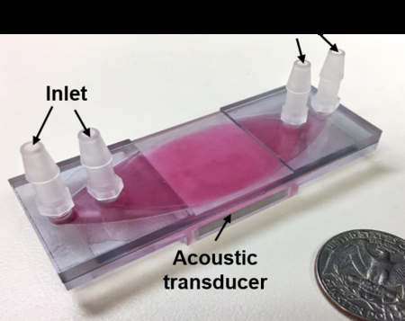
Graphic Content Entry: A plastic-based acoustofluidic device for high-throughput platelet separation consisting of a transducer and a disposable chip.
Introduction
Platelet separation is an important medical procedure used in clinical medicine for platelet donation and treatment of essential thrombocytosis.1–5 Additionally, platelets are a rich source of growth factors and accelerate the recovery of human bones and soft tissues.6 A currently popular protocol used to separate platelets or achieve apheresis uses a continuous centrifugation device that separates blood from patients into various fractions based on differences in density (red blood cells>white blood cells>platelets>plasma). However, this approach requires long-duration (several hours needed),7 and high-speed (>2,000g) centrifugation,8 which may negatively affect the functionality and integrity of the platelets. These drawbacks often confound treatment goals.9
Recently, various alternative attempts have been made at isolating platelets from human whole blood.10–17 Most of these attempts are based on microfluidic platforms which introduce external forces such as hydrophoretic,15,18–23 dielectric,24,25 inertial focusing,22,23,26 and acoustic forces.27–32 The throughput of these platforms, however, is often insufficient (<<1 mL/min) to substitute them for conventional platelet separation, particularly for clinical use. The ability to isolate platelets from whole blood with high throughput can reduce blood-processing time, which both protects blood quality and saves donors’ time. Although recently several high-throughput (~10 mL/min) platelet-separation methods have been demonstrated,33,34 these methods require channel materials of high acoustic impedance, such as stainless steel or glass. These materials are problematic because plasma proteins quickly adhere to the surface, which can result in the adhesion and activation of platelets within the channel.35 In addition, the cost of stainless steel and glass, which are the major components of the devices, make them unsuitable for disposable medical devices.
In this work, we demonstrate a plastic-based, disposable acoustic device to conduct fast, efficient, and biocompatible platelet separation. Experiments show that our disposable acoustic device isolates platelets at a high platelet recovery rate (87.3%) and high removal rate (88.9%) for red blood cells (RBCs) and white blood cells (WBCs) at a throughput of 20 mL/min whole blood. Our device uses an “out-of-plane” design, which is fundamentally different from the existing plastic-based acoustofluidic devices, which use a “in-plane” resonator mode and thus require precise adjustment of the dimensions of microchannels and can only achieve a relatively low throughput (25–500 μL/min).36,37 Using human whole blood, our plastic-based acoustofluidic device achieved not only a high throughput (20 mL/min) but also over 85% for both the platelet recovery rate and the RBC/WBC removal rate. Following the platelet separation process, we evaluated the platelet activation level, hypotonic shock response (HSR), platelet aggregation activity, and morphology. All of these results indicate that the platelets isolated using our plastic-based acoustic device are of better quality than those isolated using the gold-standard method (i.e., centrifugation). Not only is our acoustic device disposable, low-cost, and easy to prepare, but it is also fast, efficient, and biocompatible. Taken together, these advantages make the device an excellent candidate to replace conventional platelet separation approaches.
Materials and methods
Mechanism
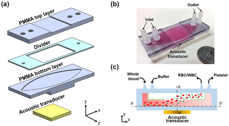
Figs. 1(a–c) show an exploded 3D diagram, photograph, and schematic of the acoustic-based platelet separation device, respectively. The whole device consists of a plastic multi-layered structure and an acoustic transducer. The multi-layered structure is composed of two polymethyl methacrylate (PMMA) sheets as top and bottom layers, respectively, and a polyester film as a divider. The PMMA sheet and channel form a quarter-wavelength resonator which produces a pressure node near the top layer and yields effective separation.38,39 The pressure node near the top layer moves cells from the blood to the buffer above it in a manner similar to previously presented quarter-wavelength resonators.34,40–44 Plastics such as PMMA and polyester are routinely used in medical devices due to their biocompatibility with human blood.45 Furthermore, PMMA sheets can be easily mechanically machined or laser-cut into any shapes of different thicknesses, which allows for flexibility of the device’s design. The acoustic transducer was attached underneath the structure and had a resonance frequency of 610 kHz. The frequency was selected so that enough acoustic radiation force was provided, and so that half of the wavelength was equal to the thickness of the PMMA top layer, the PMMA thickness and the half-wavelength of the working frequency must be equal to form the proper quarter-wavelength resonator used for separation. The device has two inlets and two outlets. Whole blood and buffer enter the channel from two inlets, respectively, while the divider in the middle of the channel separates these fluids before they mix in the acoustic working area. When the acoustic transducer matches the resonance frequency, the acoustic wave propagates through the bottom PMMA layer and into the channel. The propagating wave is a monotonic pressure amplitude gradient in the channel.43,46 Our design allows a pressure node to form at the top of the channel while an anti-node forms at the bottom of the channel.
Figure 1.
(a) Exploded 3D diagram (an oval channel is also carved into the bottom of the PMMA top layer, which provides a pathway for the buffer solution), (b) photograph, and (c) schematic of the acoustic platelet separation device. a-a’ and b-b’ are two cross-sections of the device.
When blood cells enter the channel, they are subject to various acoustic radiation forces depending on size differences; this is shown in the following equations.34,47,48
| (1) |
| (2) |
Eq. (1) describes the relationship between the properties of the cell (volume Vc, contrast factor Φ), acoustic parameters (pressure p0, the wavenumber k), vertical distance from the pressure (x), and acoustic radiation force (FR). Eq. (2) defines the acoustic contrast factor ϕ, which is a function of the density and compressibility of the cell, ρc and βc, and the media, ρm and βm, respectively.
As the blood and buffer flow through the acoustic pressure area, all the blood components are subject to an acoustic radiation force, as defined by cell properties, acoustic parameters of pressure and wavenumber, as well as the vertical distance from the pressure. Because RBCs and WBCs (RBC: 6–8 μm, WBC: 12–17 μm) are larger than platelets (2 ~ 3 μm), they are subject to greater radiation forces than platelets. Size predominately determines the variation in the acoustic radiation force and corresponding particle trajectories, with the density and compressibility relationship between particles and the medium also contributing to the separation.49–52 Thus, RBCs/WBCs are pushed into the buffer near the top layer, while platelets remain near the bottom layer and thus are separated.
Device Fabrication
Three layers of plastic are required to assemble the acoustic device. The two PMMA sheets were machined by a computer numerical control (CNC) cutting machine as the top and bottom layers, and the polyester film was laser-cut as the divider and sandwiched between the top and bottom layers. Four plug-connectors connected the inlets and outlets with the tubing. An ultrasonic couplant was used to couple the transducer with the device, ensuring that the ultrasonic energy could be effectively delivered into the channel. Moreover, the couplant could be easily removed and cleaned, which enabled us to reuse and recycle the acoustic transducer.
Acoustic Field
To understand the acoustic pressure field inside our plastic-based acoustic chip, a hydrophone (HNC0100, Onda Corporation, USA) was employed along with an oscilloscope (DPO4104, Tektronix, USA) to measure the acoustic field after the transducer was attached to the bottom layer. A homemade 3-D scanning platform controlled with the LabVIEW software (NI Corporation, USA) was used to control the scanning of the field. The device was placed into a sink for measuring the acoustic field to identify the uniformity of the output transducer energy. The relationship between the driving voltage of the transducer and acoustic pressure was also calibrated with the hydrophone.
Numerical Simulation
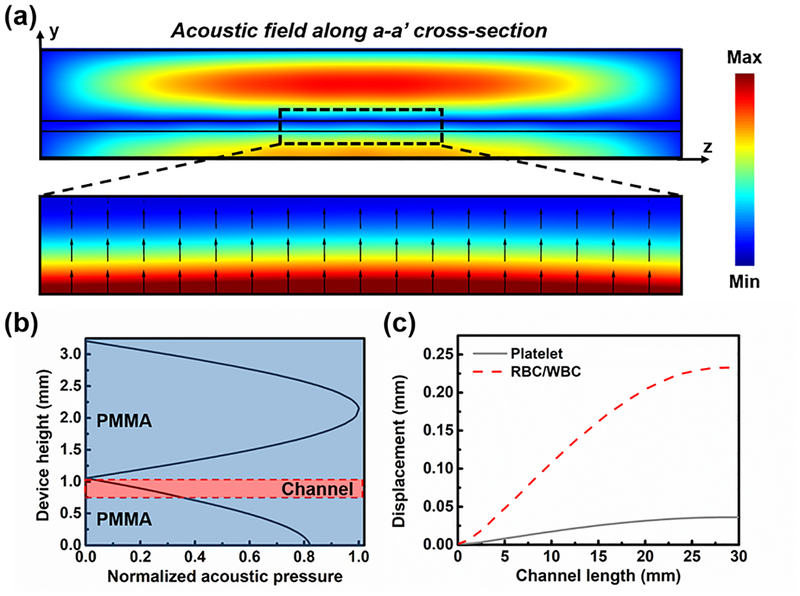
To understand the acoustic pressure and cell displacement in the designed acoustic platelet separation device, numerical simulation was conducted using a finite-element-based software package, COMSOL Multiphysics® version 5.2a (COMSOL, USA). Firstly, the “Pressure Acoustics” module was used to solve the acoustic field on a vertical cross-section of the device within the transducer-functioning area by using a “Frequency Domain” model solver at 610 kHz, the resonance frequency of the transducer applied in the experiment. The acoustic pressure used for the simulation was the measured value, while the corresponding normal velocity was calculated and added to the bottom of the device. The corresponding acoustic radiation force for WBCs, RBCs, and platelets was calculated based on Eq. (1) and (2). The “Laminar Flow” and “Particle Tracing for Fluid Flow” modules were used to predict the RBC/WBC and platelet displacement in the lateral cross-section inside the channel under the acoustic radiation force and the Stokes drag force at a flow rate of 7 ml/min. The simulation results show that the absolute value of acoustic pressure decreased from bottom to top within the channel (Figs. 2(a) and 2(b)); as a result, the cells in the channel would be pushed upward to the top of the channel (Fig. 2(c)). Because of their size difference, RBCs/WBCs were subject to stronger acoustic radiation force than the platelets. Thus, the RBCs/WBCs were separated from platelets at the end of the channel by 250 μm. These simulation results validated the working mechanism of our device. All the parameters used in the simulation are listed in Tables S1 and S2 in the Supplementary Information.
Figure 2.
(a) The simulated absolute acoustic pressure field of the a-a’ cross-section of the acoustic device for platelet separation, and the Gorkov’s potential and acoustic radiation force direction in the channel. (b) The normalized acoustic pressure distribution along the middle line of the acoustic device. (c) The simulated trajectory of the platelets and RBCs/WBCs along the channel length when exposed to the acoustic field.
System Setup
The blood sample and buffer solution were delivered into the acoustic device through a homemade peristaltic pump, which has four pumping channels and provides a range of flow rates from 1 to 50 mL/min. An RF signal generator (AFG 3011, Tektronic, USA) and a power amplifier (25A250A, Amplifier Research, USA) provided coherent AC signals to the acoustic transducer. The resonance frequency of the acoustic transducer after being bonded to the fluidic chamber was measured using a vector network analyzer (VNA 2180, Array Solutions, USA).
Blood Samples and Buffer Solution
The human whole blood sample was purchased from Zen-Bio, Inc. 10% sterile dextrose solution, which is commonly used for platelet storage and is biocompatible at this concentration,53 was used as the buffer solution to tune the acoustic impedance of the medium.48 A hematology analyzer (Ac·T diff2, Beckman Coulter, USA) was used before and after platelet separation processing. The functionality and quality of platelets were evaluated by the expression level of CD 62P (P-selectin), morphology score, platelet aggregation activity, and the HSR. The expression level of P-selectin on the platelets’ surface was measured using a human sP-selectin immunoassay (R&D Systems, Inc., USA). To characterize the morphology score,54,55 platelet samples were diluted with plasma to 300,000 platelets per μL, and a drop (10 μL) was placed on a slide and examined under a microscope. 100 platelets were counted and evaluated for morphology. The morphology score was then presented as the percentage of discoid platelets (discs and altered discs). The platelet HSR and platelet aggregation were measured with an aggregometer (500VS, Chrono-Log, USA).
Results
Device performance
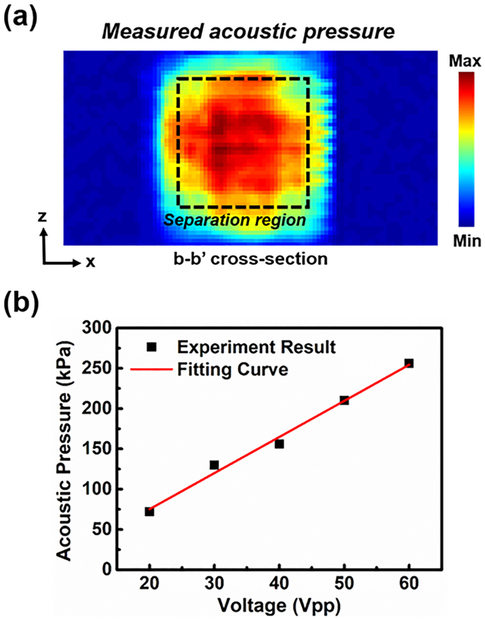
The uniformity of the input acoustic energy was essential to the platelet separation performance. An asymmetrical acoustic pressure field might have induced disordered motion of the fluid, which would have mixed the sheath flow and whole blood. To evaluate the acoustic energy after the acoustic transducer was attached to the bottom layer, the acoustic pressure field was measured across the bottom layer area (Fig. 3(a)). The field was nearly uniform in the central area, since the transducer was attached at the bottom of the layer. The pressure outside the area covered by the transducer was nearly zero, which was outside of the effective separation area. The acoustic pressure (Fig. 3(b)) was linearly proportional to the voltage, which was beneficial for the acoustic power adjustment during the experiment. Moreover, compared to our previous device made of stainless steel,56 whose acoustic impedance is about 15 times higher than that of PMMA, our plastic-based separation device enables the transmission of greater acoustic energy into the channel due to a lower reflection factor between the coupling layer and plastic bottom layer. The efficiency is improved when more acoustic energy is consumed.
Figure 3.
(a) The measured acoustic field of the b-b’ cross-section. (b) The measured and fitted acoustic pressure as a function of the driving voltage. Each data point represents five independent measurements ± standard deviation from a hydrophone; however, because the hydrophone is stable and can reproducibly measure the acoustic pressure, the measured acoustic pressure barely changed among five independent measurements (error bars are smaller than data marker size).
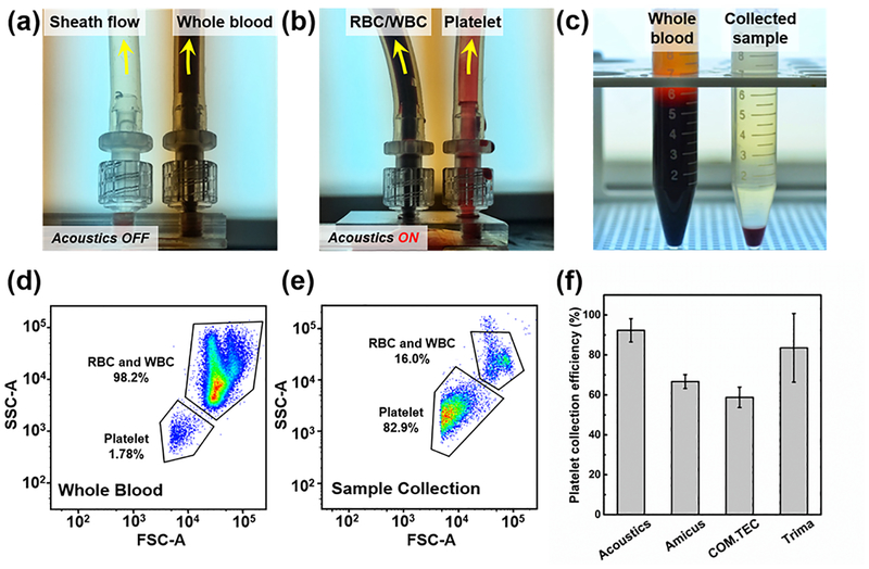
In the platelet separation process, two distinct flow rates were applied to the two inlets to avoid mixing the two flows. The flow rate of the sheath flow was twice that of the blood flow. As shown in Figs. 4 (a) and (b), when the transducer was turned off, all the whole blood flowed to the right outlet, while the sheath flowed to the left outlet. After turning on the transducer, the RBCs/WBCs were separated and directed to the left outlet. Fig. 4(c) shows the input sample (i.e., whole blood, left) and the separated platelet sample (right). Although some RBCs were still in the separated sample, over 85% of RBCs/WBCs were removed from the whole blood. Using flow cytometry, we quantitatively characterized the platelet separation performance, as shown in Figs. 4(d) and (e). In whole blood, the RBCs/WBCs constituted the majority of the cellular components, and a few (1.78%) components were platelets (Fig. 4(d)). After the acoustic platelet separation process, the vast majority of the RBCs/WBCs were removed, and the platelets isolated and enriched to 82.9% in the collected sample (Fig. 4(e)). The forward scattering signal of platelets was slightly cut off, possibly due to the lowest size limit of the flow cytometer, which may have been affecting the accuracy of the platelet count. Throughout the experiments, a sample flow rate of 20 mL/min and driving voltage of 45 Vpp were applied for our acoustic devices. As shown in Fig. 4(f), the platelet collection efficiency of the plastic-based acoustic device was compared to three commercial plateletpheresis systems which were studied by Keklik, M. et al.57 The platelet collection efficiency of our acoustic device can reach a maximum of 92.3%, which is nearly 10% higher than the best performance of commercial plateletpheresis product. Moreover, the RBC/WBC removal performance is also compared to commercial plateletpheresis product by comparing the hemoglobin (Hb) level, which serves as an oxygen-transport metalloprotein in red blood cells, before and after platelet separation process. As shown in Table S3 in the Supplementary Information, although the platelet recovery rate is lower than that of our acoustofluidic method, the commercial plateletpheresis has a relatively higher RBCs/WBCs removal rate58,59 of 93.6% for Amicus, 94.3% for COM.TEC, and 95.5% for Trima, compared to 88.2% achieved at a throughput of 20 mL/min for our acoustofluidic method.
Figure 4.
(a) When the acoustic transducer is off, whole blood are collected at the right outlet; (b) when the acoustic transducer is on, RBCs/WBCs are separated to the left outlet in response to the acoustic radiation force, and therefore, the platelets are collected at the right outlet. (c) The comparison of whole blood (left) and collected platelet sample (right). The flow cytometry results using (d) the whole blood and (e) collected sample. (f) The comparison of platelet collection efficiency between our acoustic device and three commercial plateletpheresis systems (Fenwal Amicus, Fresenius COM.TEC, and Trima Accel). The data of commercial plateletpheresis systems is studied by Keklik, M. et al.36 The data represent three independent experiments as average ± standard deviation.
High-Throughput Platelet Separation
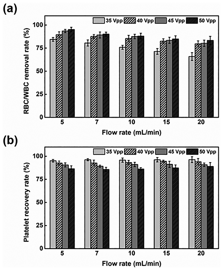
The flow rate and driving voltage applied to the acoustic transducer were the two factors that primarily influenced the platelet separation performance. Differing from most of the acoustic separation methods,60–62 where bubbles can be easily generated in the channel due to increasing temperature, in our device, heat induced due to acoustic energy will flow to the buffer/blood flow through conduction, such that the temperature in the channel stays relatively low. To further evaluate the performance of acoustic platelet separation, we quantitatively characterized the RBC/WBC removal and platelet recovery rates as functions of the flow rate and driving voltage. The removal rate is the ratio of RBCs/WBCs collected from the left outlet (i.e., the RBC/WBC outlet) to the RBCs/WBCs introduced at the inlet, while the recovery rate is the ratio of isolated platelets collected from the right outlet (i.e., the platelet outlet) to the platelets introduced at the inlet. As increases in flow rate reduced the time in which blood components were subject to acoustic radiation force, we expected to see reduced separation of large blood cells. As shown in Fig. 5(a), when voltage was fixed and flow rate increased from 5 to 20 ml/min, the RBC/WBC removal rate was reduced by 13%, and the platelet recovery rate was barely affected. Meanwhile, when the driving voltage was increased from 35 to 50 Vpp, the RBC/WBC removal rate was improved, while the platelet recovery rate was compromised. When a greater voltage was applied, a greater acoustic radiation force acted on the RBCs/WBCs; similarly, the platelets were subject to a greater acoustic radiation force. Thus, the displacement of all the blood cells including the RBCs/WBCs and platelets increased, which improved the RBC/WBC removal rate but decreased the platelet recovery rate. Nevertheless, when the driving voltage reached over 40 Vpp at a flow rate of the blood sample ranging from 5 to 20 mL/min, our device demonstrated over 83% for both the RBC/WBC removal rate and platelet recovery rate. Our plastic-based acoustofluidic device, when operated under the optimized flow rate (7 mL/min) and optimized driving voltage (45 Vpp), could reach over 90% for both the RBC/WBC removal rate and platelet recovery rate. It should be also noted that the flow cytometry results for the collected sample show a relatively lower RBC/WBC concentration than the results suggested by the data in Figure 5(a), which was derived by comparing the RBCs/WBCs introduced into and collected out of the left outlet. One potential reason for this inconsistency is that RBCs/WBCs tend to aggregate and forms clusters within the flow;63 this means that multiple RBCs/WBCs are counted as a single one. Another possible reason is that a large number of RBCs/WBCs in the whole blood may stick to the bottom of the channel, or to the tubing of the device, which causes a decrease in the RBCs/WBCs measured from the right outlet.
Figure 5.
(a) The RBC/WBC removal rate and (b) platelet recovery rate of the acoustic platelet separation device as the functions of the flow rate and driving voltage applied to the acoustic transducer. The data represent three independent experiments as average ± standard deviation.
Platelet Quality and Function
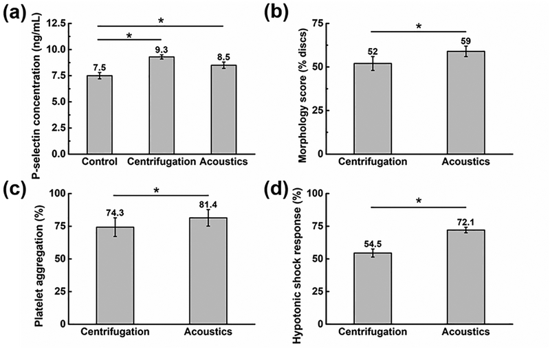
The quality of the isolated platelets was evaluated using the following parameters: P-selectin, morphology score, platelet aggregation activity, and HSR (Fig. 6). The results show that compared to centrifugation,6,64,65 the acoustic platelet separation technology does much less damage to the platelets. As a positive control group, platelets were also recovered upon centrifugation, where 10 mL blood sample was centrifuged for 12 min at 200 g, followed by collection and then centrifuging the top and middle layers for 5 min at 1200 g to obtain the platelet-rich plasma.64,66 The expression level of CD 62P (P-selectin) was adopted to compare the activation levels for the platelets isolated by our acoustic technique to the centrifugation, and for the untreated platelets in the original whole blood as the negative control group. As shown in Fig. 6(a), compared to the negative control samples, the platelet activation level increased by only 13.3% for the platelets isolated by our acoustic platelet separation technique, while it increased by 24% for the platelets recovered by the centrifugation. Moreover, the acoustic separation, when compared to the centrifugation, also had a higher morphology score (Fig. 6(b)), suggesting that the discoid platelets were of greater integrity after acoustic separation than after centrifugation.67 In terms of the platelet aggregation activity, 5 μM adenosine diphosphate (ADP) was used as the agonist, and the corresponding platelet-poor plasma was utilized as control and transmission standardization. Platelets separated by our acoustic technology show higher aggregation ratios compared to the centrifugation result (Fig. 6(c)), which implies a better platelet functionality. Finally, the acoustically isolated platelets had higher HSR (Fig. 6(d)), which indicates that the platelets had higher viability.68 Results were obtained from using three independent blood samples and analyzed using a one-way ANOVA post hoc test. Through the statistical analysis, we concluded that the quality of platelets isolated using our acoustic method is statistically better than those isolated using the centrifugation method. These results indicate that when one uses the plastic-based acoustic chip, the integrity of isolated platelets will be preserved better than by centrifugation.
Figure 6.
Evaluation of the quality of the isolated platelets by our acoustic platelet separation technique and the centrifugation: (a) P-selectin characterization, (b) morphology score quantification, (c) platelet aggregation activity measurement, and (d) hypotonic shock response analysis. Data represents average ± standard deviation from three independent experiments (*p < 0.05).
Discussion
Current plateletpheresis and apheresis instruments for clinical use evolved from blood separation technology developed in the 1940’s as part of a wartime effort to provide blood fractions to injured soldiers. Consequently, these instruments have been exclusively developed for treatment of adult human subjects and have not been optimally designed for use in neonates and infants who typically have 1/10th the blood volume of adults. Smaller instruments are additionally needed to facilitate research. Due to the size of current instrumentation, research applications involving centrifugal-based devices have been restricted to human subjects, or large animals (dogs and non-human primates) weighing >10 kg. Current technology has not evolved to adapt for smaller blood volumes essential for performing research in smaller animals.
In this article, we describe a novel technology that is capable of separating cells in a fluid medium in both large (e.g., 1,000 mL extracorporeal volume) and small volumes (e.g., 3 mL extracorporeal volume) using sound waves. This technique offers a powerful tool for label-free separation of a variety of cellular and sub-cellular particles for both therapeutic, diagnostic, and research applications. Its versatility makes it suitable for platelet separation for adult human subjects, neonates and infants, large animals (such as dogs and horses), and small animals (such as mice).
Our plastic-based acoustic device isolates platelets at 88.9% for the RBC/WBC removal rate, 87.3% for the platelet recovery rate, and 20 mL/min for the throughput. The RBC/WBC removal rate and platelet recovery rate can be improved to over 90% by optimizing the device’s design and operation parameters. It is worth mentioning that, the WBC count of the blood samples we purchased (1.2–5.5×10³/μL) is lower than a typical WBC count from fresh blood (4–11×103/μL). This is because WBCs die relatively easily and their number decreases during the shipping process (typically 1–2 days). Meanwhile, in the collected sample, the WBC count given by the blood analyzer is always 0; this is most likely because the number of WBCs in the sample is lower than the detection limit (0.01×10³/μL) of the equipment. Thus, the RBC and WBC removal rates were combined to identify the separation efficiency of our acoustofluidic device. Accounting for the limitations of the equipment and the imposed detection limit, the maximum remaining WBCs would be 10/μL, which indicates that the minimum WBC removal rate would be ~99.2%. Thus, in one unit of collected platelet sample, the estimated maximum WBC number is ~2.5 ×10⁶ which is above the recommended contamination level of 1×10⁶ set by Council of Europe69 but below 5×10⁶ as required by the AABB standards.70 In our acoustic device, a low-power-intensity acoustic field is applied to the blood components for several seconds. The operational parameters of our device are comparable to the power and intensity used in ultrasonic imaging, which is regarded as a safe method (even for fetal imaging). The gold-standard platelet separation approach, centrifugation, on the other hand, typically lasts several hours; the components are exposed to strong forces for a much longer time. Thus, the gentle process used in our acoustic device will have less of a negative effect on the isolated platelets and provide a higher quality sample.
Our acoustofluidic devices still have some drawbacks. Its throughput (20 mL/min) is still lower than those of high-end plateletpheresis devices (up to 80 mL/min). In addition, the traditional plateletpheresis equipment can separate platelets from plasma to obtain platelet samples that has no contaminants such as cell-free DNA and cytokines, while our device has not yet demonstrated this feature. Nevertheless, our acoustic device possesses many inherent advantages including high biocompatibility, low cost, and ease of preparation and operation. With these advantages, it is suitable not only for platelet separation but also for label-free separation of many other cellular and sub-cellular particles.
Supplementary Material
Acknowledgements
We acknowledge support from the National Institutes of Health (R43HL140800, R01HD086325, R44GM125439, and R33CA223908), and the National Science Foundation (ECCS-1807601).
Footnotes
Conflicts of interest
T.J.H. has four US patents (patent numbers: 8,573,060; 9,608,547; 9,606,086; and 9,757,699) related to acoustofluidics and acoustic tweezers. He has also co-founded a start-up company, Ascent Bio-Nano Technologies Inc., to commercialize technologies involving acoustofluidics and acoustic tweezers.
References
- 1.Nam J, Lim H, Kim D and Shin S, Lab Chip, 2011, 11, 3361. [DOI] [PubMed] [Google Scholar]
- 2.Dykes J, Lenshof A, Åstrand-Grundström IB, Laurell T and Scheding S, PLoS One, DOI: 10.1371/journal.pone.0023074. [DOI] [PMC free article] [PubMed] [Google Scholar]
- 3.Soliman A, Eldosoky M and Taha T, Bioengineering, 2017, 4, 28. [DOI] [PMC free article] [PubMed] [Google Scholar]
- 4.Gerhardson T, Sporbert B, Mealey D, Rust MJ and Lipkens B, Blood, 2013, 122, 3665 [Google Scholar]
- 5.Greist A, Ther. Apher, 2002, 6, 36–44. [DOI] [PubMed] [Google Scholar]
- 6.Anitua E, Pino A and Orive G, J. Wound Care, 2016, 25, 680–687. [DOI] [PubMed] [Google Scholar]
- 7.Fontana S, Mordasini L, Keller P and Taleghani BM, Transfusion, 2006, 46, 2004–2010. [DOI] [PubMed] [Google Scholar]
- 8.Basu D and Kulkarni R, Indian J. Anaesth, 2014, 58, 529. [DOI] [PMC free article] [PubMed] [Google Scholar]
- 9.Macher S, Sipurzynski-Budrass S, Rosskopf K, Rohde E, Griesbacher A, Groselj-Strele A, Lanzer G and Schallmoser K, Vox Sang, 2010, 99, 332–340. [DOI] [PubMed] [Google Scholar]
- 10.Guldiken R, Jo MC, Gallant ND, Demirci U and Zhe J, Sensors, 2012, 12, 905–922. [DOI] [PMC free article] [PubMed] [Google Scholar]
- 11.Wang Z and Zhe J, Lab Chip, 2011, 11, 1280. [DOI] [PubMed] [Google Scholar]
- 12.Jiang X, Wong KHK, Khankhel AH, Zeinali M, Reategui E, Phillips MJ, Luo X, Aceto N, Fachin F, Hoang AN, Kim W, Jensen AE, Sequist LV, Maheswaran S, Haber DA, Stott SL and Toner M, Lab Chip, 2017, 17, 3498–3503. [DOI] [PMC free article] [PubMed] [Google Scholar]
- 13.B??ing AN, van der Pol E, Grootemaat AE, Coumans FAW, Sturk A and Nieuwland R, J. Extracell. Vesicles, DOI: 10.3402/jev.v3.23430. [DOI] [PMC free article] [PubMed] [Google Scholar]
- 14.Aatonen M, Valkonen S, Böing A, Yuana Y, Nieuwland R and Siljander P, in Methods in Molecular Biology, 2017, vol. 1545, pp. 177–188. [DOI] [PubMed] [Google Scholar]
- 15.Choi S, Song S, Choi C and Park J-K, Lab Chip, 2007, 7, 1532. [DOI] [PubMed] [Google Scholar]
- 16.Goetzl EJ, Goetzl L, Karliner JS, Tang N and Pulliam L, FASEB J, 2016, 30, 2058–2063. [DOI] [PMC free article] [PubMed] [Google Scholar]
- 17.Hou HW, Bhagat AAS, Lee WC, Huang S, Han J and Lim CT, Micromachines, 2011, 2, 319–343. [Google Scholar]
- 18.Choi S, Ku T, Song S, Choi C and Park J-K, Lab Chip, 2011, 11, 413–418. [DOI] [PubMed] [Google Scholar]
- 19.Arifin DR, Yeo LY and Friend JR, Biomicrofluidics, 2007, 1, 14103. [DOI] [PMC free article] [PubMed] [Google Scholar]
- 20.Liu Y and Liu WK, J. Comput. Phys, 2006, 220, 139–154. [Google Scholar]
- 21.Di Carlo D, Edd JF, Irimia D, Tompkins RG and Toner M, Anal. Chem, 2008, 80, 2204–2211. [DOI] [PubMed] [Google Scholar]
- 22.Tay HM, Kharel S, Dalan R, Chen ZJ, Tan KK, Boehm BO, Loo SCJ and Hou HW, NPG Asia Mater, 2017, 9, e434. [Google Scholar]
- 23.Hou HW, Bhattacharyya RP, Hung DT and Han J, Lab Chip, 2015, 15, 2297–2307. [DOI] [PMC free article] [PubMed] [Google Scholar]
- 24.Pommer MS, Zhang Y, Keerthi N, Chen D, Thomson JA, Meinhart CD and Soh HT, Electrophoresis, 2008, 29, 1213–1218. [DOI] [PubMed] [Google Scholar]
- 25.Piacentini N, Mernier G, Tornay R and Renaud P, Biomicrofluidics, DOI: 10.1063/1.3640045. [DOI] [PMC free article] [PubMed] [Google Scholar]
- 26.Di Carlo D, Edd JF, Irimia D, Tompkins RG and Toner M, Anal. Chem, 2008, 80, 2204–2211. [DOI] [PubMed] [Google Scholar]
- 27.Petersson F, Åberg L, Swärd-Nilsson AM and Laurell T, Anal. Chem, 2007, 79, 5117–5123. [DOI] [PubMed] [Google Scholar]
- 28.Gedge M and Hill M, Lab Chip, 2012, 12, 2998. [DOI] [PubMed] [Google Scholar]
- 29.Zhang SP, Lata J, Chen C, Mai J, Guo F, Tian Z, Ren L, Mao Z, Huang P-H, Li P, Yang S and Huang TJ, Nat. Commun, 2018, 9, 2928. [DOI] [PMC free article] [PubMed] [Google Scholar]
- 30.Ahmed D, Ozcelik A, Bojanala N, Nama N, Upadhyay A, Chen Y, Hanna-Rose W and Huang TJ, Nat. Commun, 2016, 7, 11085. [DOI] [PMC free article] [PubMed] [Google Scholar]
- 31.Ozcelik A, Rufo J, Guo F, Gu Y, Li P, Lata J and Huang TJ, Nat. Methods, 2018, 15, 1021–1028. [DOI] [PMC free article] [PubMed] [Google Scholar]
- 32.Wu M, Ouyang Y, Wang Z, Zhang R, Huang P-H, Chen C, Li H, Li P, Quinn D, Dao M, Suresh S, Sadovsky Y and Huang TJ, Proc. Natl. Acad. Sci, 2017, 114, 10584–10589. [DOI] [PMC free article] [PubMed] [Google Scholar]
- 33.Chen Y, Wu M, Ren L, Liu J, Whitley PH, Wang L and Huang TJ, Lab Chip, 2016, 16, 3466–3472. [DOI] [PMC free article] [PubMed] [Google Scholar]
- 34.Adams JD, Ebbesen CL, Barnkob R, Yang AHJ, Soh HT and Bruus H, J. Micromechanics Microengineering, 2012, 22, 075017. [Google Scholar]
- 35.Mrowietz C, Franke RP, Seyfert UT, Park JW and Jung F, Clin. Hemorheol. Microcirc, 2005, 32, 89–103. [PubMed] [Google Scholar]
- 36.Silva R, Dow P, Dubay R, Lissandrello C, Holder J, Densmore D and Fiering J, Biomed. Microdevices, 2017, 19, 70. [DOI] [PubMed] [Google Scholar]
- 37.Mueller A, Lever A, V Nguyen T, Comolli J and Fiering J, J. Micromechanics Microengineering, 2013, 23, 125006. [Google Scholar]
- 38.Hawkes JJ, Barber RW, Emerson DR and Coakley WT, Lab Chip, 2004, 4, 446–452. [DOI] [PubMed] [Google Scholar]
- 39.Johnson DA and Feke DL, Sep. Technol, 1995, 5, 251–258. [Google Scholar]
- 40.Glynne-Jones P, Boltryk RJ, Hill M, Harris NR and Baclet P, J. Acoust. Soc. Am, 2009, 126, EL75–EL79. [DOI] [PubMed] [Google Scholar]
- 41.Hawkes JJ, Gröschl M, Benes E, Nowotny H and Coakley WT, Proc. Forum Acusticum 2002, 2002, 6 [Google Scholar]
- 42.Glynne-Jones P, Boltryk RJ, Hill M, Zhang F, Dong L, Wilkinson JS, Melvin T, Harris NR and Brown T, Anal. Sci. Int. J. Japan Soc. Anal. Chem, 2009, 25, 285–291. [DOI] [PubMed] [Google Scholar]
- 43.Townsend RJ, Hill M, Harris NR and McDonnell MB, Ultrasonics, 2008, 48, 515–520. [DOI] [PubMed] [Google Scholar]
- 44.Hill M, J. Acoust. Soc. Am, 2003, 114, 2654. [DOI] [PubMed] [Google Scholar]
- 45.Frazer RQ, Byron RT, Osborne PB and West KP, J. Long. Term. Eff. Med. Implants [DOI] [PubMed] [Google Scholar]
- 46.Glynne-Jones P, Boltryk RJ and Hill M, Lab Chip, 2012, 12, 1417. [DOI] [PubMed] [Google Scholar]
- 47.Bruus H, Lab Chip, 2012, 12, 1014. [DOI] [PubMed] [Google Scholar]
- 48.Deshmukh S, Brzozka Z, Laurell T and Augustsson P, Lab Chip, 2014, 14, 3394–3400. [DOI] [PubMed] [Google Scholar]
- 49.Torr GR, Am. J. Phys, 1984, 52, 402–408. [Google Scholar]
- 50.HASEGAWA T and YOSIOKA K, J. Acoust. Soc. Am, 1969, 1139. [Google Scholar]
- 51.Yasuda K and Kamakura T, Appl. Phys. Lett, 1997, 71, 1771. [Google Scholar]
- 52.Hartono D, Liu Y, Tan PL, Then XYS, Yung L-YL and Lim K-M, Lab Chip, 2011, 11, 4072. [DOI] [PubMed] [Google Scholar]
- 53.Chen Y, Wu M, Ren L, Liu J, Whitley PH, Wang L and Huang TJ, Lab Chip, 2016, 16, 3466–3472. [DOI] [PMC free article] [PubMed] [Google Scholar]
- 54.Wagner SJ, Vassallo R, Skripchenko A, Einarson M, Seetharaman S and Moroff G, Transfusion, 2008, 48, 1072–1080. [DOI] [PubMed] [Google Scholar]
- 55.Wagner SJ, Skripchenko A, Myrup A, Thompson-Montgomery D, Awatefe H and Moroff G, Transfusion, 2010, 50, 1028–1035. [DOI] [PubMed] [Google Scholar]
- 56.Lenshof a, Evander M, Laurell T and Nilsson J, Lab Chip, 2012, 12, 684–95. [DOI] [PubMed] [Google Scholar]
- 57.Keklik M, Eser B, Kaynar L, Solmaz M, Ozturk A, Yay M, Birekul A, Oztekin M, Sivgin S, Cetin M and Unal A, Transfus. Apher. Sci, 2014, 51, 193–196. [DOI] [PubMed] [Google Scholar]
- 58.Keklik M, Eser B, Kaynar L, Solmaz M, Ozturk A, Yay M, Birekul A, Oztekin M, Sivgin S, Cetin M and Unal A, Transfus. Apher. Sci, 2014, 51, 193–196. [DOI] [PubMed] [Google Scholar]
- 59.Tendulkar A and Rajadhyaksha SB, Asian J. Transfus. Sci, 2009, 3, 73–7. [DOI] [PMC free article] [PubMed] [Google Scholar]
- 60.Li S, Ma F, Bachman H, Cameron CE, Zeng X and Huang TJ, J. Micromechanics Microengineering, 2017, 27, 15031. [DOI] [PMC free article] [PubMed] [Google Scholar]
- 61.Wu M, Huang P, Zhang R, Mao Z, Chen C, Kemeny G, Li P, V Lee A, Gyanchandani R and Armstrong AJ, Small, 2018, 14, 1801131. [DOI] [PMC free article] [PubMed] [Google Scholar]
- 62.Wu M, Chen K, Yang S, Wang Z, Huang P-H, Mai J, Li Z-Y and Huang TJ, Lab Chip. [Google Scholar]
- 63.Tomaiuolo G, Lanotte L, Ghigliotti G, Misbah C and Guido S, Phys. Fluids, 2012, 24, 51903. [Google Scholar]
- 64.Perez AGM, Lana JFSD, Rodrigues AA, Luzo ACM, Belangero WD and Santana MHA, ISRN Hematol, 2014, 2014, 1–8. [DOI] [PMC free article] [PubMed] [Google Scholar]
- 65.Chandler WL, Blood Coagul. Fibrinolysis, 2012, 1.22036808 [Google Scholar]
- 66.Dhurat R and Sukesh M, J. Cutan. Aesthet. Surg, 2014, 7, 189. [DOI] [PMC free article] [PubMed] [Google Scholar]
- 67.Germing U, Platzbecker U, Giagounidis A and Aul C, Br. J. Haematol, 2007, 138, 399–400. [DOI] [PubMed] [Google Scholar]
- 68.Kececi Y, Ozsu S and Bilgir O, Wounds a Compend. Clin. Res. Pract, 2014, 26, 232–8. [PubMed] [Google Scholar]
- 69.EDQM, Guide to the preparation, use and quality assurance of blood components, 2015, vol. 0. [Google Scholar]
- 70.Klein HG, Am. Assoc. Blood Banks. [Google Scholar]
Associated Data
This section collects any data citations, data availability statements, or supplementary materials included in this article.


